EP1003012B3 - Système optique pour la mesure de position - Google Patents
Système optique pour la mesure de position Download PDFInfo
- Publication number
- EP1003012B3 EP1003012B3 EP99121779A EP99121779A EP1003012B3 EP 1003012 B3 EP1003012 B3 EP 1003012B3 EP 99121779 A EP99121779 A EP 99121779A EP 99121779 A EP99121779 A EP 99121779A EP 1003012 B3 EP1003012 B3 EP 1003012B3
- Authority
- EP
- European Patent Office
- Prior art keywords
- reference mark
- scale
- scanning
- blocks
- mark structure
- Prior art date
- Legal status (The legal status is an assumption and is not a legal conclusion. Google has not performed a legal analysis and makes no representation as to the accuracy of the status listed.)
- Expired - Lifetime
Links
- 230000003287 optical effect Effects 0.000 title claims description 40
- 238000009826 distribution Methods 0.000 claims description 15
- 230000000295 complement effect Effects 0.000 claims description 8
- 238000005286 illumination Methods 0.000 claims description 3
- 238000012545 processing Methods 0.000 description 6
- 238000005070 sampling Methods 0.000 description 5
- 230000000694 effects Effects 0.000 description 4
- 238000003491 array Methods 0.000 description 3
- 238000011156 evaluation Methods 0.000 description 3
- 238000013461 design Methods 0.000 description 2
- 238000004519 manufacturing process Methods 0.000 description 2
- 230000005693 optoelectronics Effects 0.000 description 2
- 239000000654 additive Substances 0.000 description 1
- 230000000996 additive effect Effects 0.000 description 1
- 230000015572 biosynthetic process Effects 0.000 description 1
- 238000011109 contamination Methods 0.000 description 1
- 230000001419 dependent effect Effects 0.000 description 1
- 238000001514 detection method Methods 0.000 description 1
- 230000010339 dilation Effects 0.000 description 1
- 230000007274 generation of a signal involved in cell-cell signaling Effects 0.000 description 1
- 230000036039 immunity Effects 0.000 description 1
- 230000001795 light effect Effects 0.000 description 1
- 238000013507 mapping Methods 0.000 description 1
- 238000005259 measurement Methods 0.000 description 1
- 230000005855 radiation Effects 0.000 description 1
- 238000012546 transfer Methods 0.000 description 1
Images


Classifications
-
- G—PHYSICS
- G01—MEASURING; TESTING
- G01D—MEASURING NOT SPECIALLY ADAPTED FOR A SPECIFIC VARIABLE; ARRANGEMENTS FOR MEASURING TWO OR MORE VARIABLES NOT COVERED IN A SINGLE OTHER SUBCLASS; TARIFF METERING APPARATUS; MEASURING OR TESTING NOT OTHERWISE PROVIDED FOR
- G01D5/00—Mechanical means for transferring the output of a sensing member; Means for converting the output of a sensing member to another variable where the form or nature of the sensing member does not constrain the means for converting; Transducers not specially adapted for a specific variable
- G01D5/26—Mechanical means for transferring the output of a sensing member; Means for converting the output of a sensing member to another variable where the form or nature of the sensing member does not constrain the means for converting; Transducers not specially adapted for a specific variable characterised by optical transfer means, i.e. using infrared, visible, or ultraviolet light
- G01D5/32—Mechanical means for transferring the output of a sensing member; Means for converting the output of a sensing member to another variable where the form or nature of the sensing member does not constrain the means for converting; Transducers not specially adapted for a specific variable characterised by optical transfer means, i.e. using infrared, visible, or ultraviolet light with attenuation or whole or partial obturation of beams of light
- G01D5/34—Mechanical means for transferring the output of a sensing member; Means for converting the output of a sensing member to another variable where the form or nature of the sensing member does not constrain the means for converting; Transducers not specially adapted for a specific variable characterised by optical transfer means, i.e. using infrared, visible, or ultraviolet light with attenuation or whole or partial obturation of beams of light the beams of light being detected by photocells
- G01D5/36—Forming the light into pulses
- G01D5/366—Particular pulse shapes
Definitions
- the present invention relates to an optical position measuring device which is suitable for determining the relative position of two movable objects and provides a reference pulse signal in at least one defined relative position of the two objects.
- Known optical incremental position measuring devices usually comprise an incremental graduation track on the scale side for determining the relative position of moving objects. This track is scanned by means of a scanning unit for generating incremental signals. Furthermore, it is also often possible to generate so-called reference pulse signals to one or more uniquely defined relative positions of the two objects. For this purpose, a further reference track is arranged on the side of the scale adjacent to the incremental graduation track and comprises one or more scale reference mark structures at defined positions. These structures are also scanned by means of a scanning unit for generating the reference pulse signals.
- the scanning unit includes, inter alia, a scanning reference mark structure and one or more optoelectronic detector elements.
- the generation of a reference pulse signal is generally carried out in such a way that the reference mark structures are formed on the scale and Abtastseite so that at the respective reference position, a signal is generated which has a maximum or minimum at this position.
- the signal thus generated is switched with a reference signal in difference and placed this with the reference signal to the two inputs of a subtraction element.
- At the output of the subtraction element then there is a signal for further processing, which identifies the respective reference position.
- a reference or trigger signal for the subtracting element in optical position measuring systems, a so-called constant-amplitude steady-state signal is generally used which results from the optical scanning of a direct light track.
- those detector elements are connected to each other, which are assigned to the transmissive portions; for generating the push-pull reference pulse signal, however, those detector elements are connected to each other, which are assigned to the impermeable portions of the reference pulse scale structure.
- the two signals are then fed to a subtraction element, at the output of which the desired reference pulse signal C is applied for further processing.
- a similar variant for generating a reference pulse signal is also from the DE 19512258 known. There, too, an immediate assignment of planar detector elements to certain areas of a scale-side reference mark structure is provided. The disadvantages of this arrangement are identical to those of the document already discussed above.
- a disadvantage of this variant is, on the one hand, that a relatively bulky scanning head is necessary for scanning all structures; on the other hand, problems arise in the correct assignment of the incremental signals and the reference pulse signal, if the alignment of the mutually movable components is not correct.
- optical position measuring device having the features of claim 1.
- a specific scanning reference mark structure is used in conjunction with defined detector elements for scanning one or more scale reference mark structures. In this way, a larger possible scanning distance can be realized.
- the optical position measuring device according to the invention can be realized both in reflected light and in transmitted light.
- the corresponding position measuring device can be used for detecting linear relative movements as well as for detecting rotational relative movements.
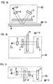
- FIG. 1a - 1c Various possible embodiments of the optical position measuring device according to the invention are in the Figures 1a - 1c shown.
- the individual variants differ in particular in the respective embodiment as an incident light measuring system according to FIG. 1 a or as a transmitted light measuring system according to the Figures 1b and 1c ,
- the illustrated embodiments of the position measuring device according to the invention each comprise a scanning unit AE and a scanned therefrom scale M.
- scanning unit AE and scale M are connected to - not shown - objects that are movable relative to each other and whose relative position using the position measuring is to be determined exactly.
- the measuring direction x ie the direction in which the scanning unit AE and the scale M are each movable relative to each other, is oriented perpendicular to the plane of the drawing in all three cases.
- the objects that are movable relative to each other can be, for example, a tool and a workpiece in a numerically controlled machine tool.
- the scanning unit AE of the exemplary embodiments shown in each case comprises a light source LQ, an optic O, a scanning A and a detector D. Furthermore, it can be provided to already arrange on the side of the scanning AE different signal processing elements, which take on a further processing of the generated scanning signals, before this a downstream evaluation, such as a numerical machine tool control, are transmitted.
- the optics O is used for collimating the beams emitted by the light source LQ.
- the optics O could also have a focusing or partial-focusing effect.
- the considerations of the invention can of course also in Position measuring are realized that have no optics between the light source LQ and the Abtastplattte A and the scale M, ie in systems with a so-called. Divergent lighting.
- the various embodiments of the position measuring device each comprise, on the scale side, an incremental graduation track (not shown), from whose optical sampling two phase-shifted incremental signals result in a known manner. Furthermore, it is provided to generate with the aid of the scanning unit AE when scanning the scale M at one or more points along the measuring path reference pulse signals, so as to produce an absolute reference in the position measurement.
- the scanning plate A and the detector unit D reference is made below in the description of FIG Figures 2-4 detailed in detail.
- FIG. 1 a is an embodiment of the position measuring device designed as an incident light system, in which the scale M or the structures arranged thereon for generating the different scanning signals consist of alternating partial regions which are designed to be reflective or non-reflective.
- the scanning A in turn comprises structures consisting of alternately arranged permeable and impermeable portions.
- the two transmitted light variants in the FIGS. 1 b and 1 c differ only in the order of arranged from the light source LQ components. So, according to the example in FIG. 1b provided, the Abtastplatte A immediately downstream of the light source LQ and the optics O, so that the beam from the scanning A then on the scale M and then on the detector unit D arrive. In contrast, in the example of the Figure 1c the arrangement of the various components such that the scanning A is located immediately in front of the detector unit and the beams first impinge on the scale M and only then reach the scanning A before they are written on the detector unit D.
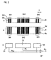
- a scale reference mark structure 10 is shown, which consist of a plurality of adjacent arranged in the measuring direction blocks BM1 - BM3 with each aperiodic sequences of subregions 10d, 10u with different optical properties.
- the bright portions 10d are permeable, while the dark portions 10u are formed impermeable.
- the reflected light variant according to FIG. 1a The different subregions 10u, 10d of the scale reference mark structure 10 would be correspondingly non-reflective and reflective, etc.
- a total of three blocks BM1 - BM3 are provided; Of course, more than three blocks per scale reference mark structure 10 can be arranged at any time. However, at least the position measuring device according to the invention requires n such blocks within the scale reference mark structure 10 with n> 2.
- the blocks of the sample reference mark structure 20 again comprise adjacently arranged subregions 20u, 20d in the measuring direction x with optically different properties.
- the partial regions 20d which are shown brightly in the drawing, are permeable, while the dark regions 20u are impermeable to the incident light bundles.
- the scanning unit AE or the scanning plate A is located exactly at the reference position x REF to be detected.
- a second group of blocks BM1, BM3, BA1, BA3 is designed such that the arrangement of the subregions 10u, 10d, 20u, 20d within these blocks BM1, BM3, BA1, BA3 on sides of the scale mouth scanning plate A is complementary to one another ,
- a transmissive portion 10d on sides of the scale M an impermeable portion 10u is to be located at the appropriate location on the side of the scanning A, etc ..
- the reflecting portions are assigned to the scale-transmissive portions on the scanning plate, and the non-reflecting portions to the scale-impermeable portions on the scanning plate.
- the dilation variant it is provided in the dilation variant to associate the non-reflective partial regions on the scale with permeable partial regions on the scanning plate and the reflective partial regions on the scale non-transmissive partial regions on the scanning plate.
- Each of the different blocks BA1-BA3 within the scanning reference mark structure is further associated with a flat optoelectronic detector element D1-D3 in fixed spatial relationship in the scanning unit AE, via which the light beams are detected, starting from the light source LQ on scanning A and scale M meet it.
- Each of the detector elements D1 - D3 in this case has a photosensitive surface or an extent in the measuring direction x, which corresponds to a multiple of the width of the various subregions 10u, 10d within the reference mark structures on the scale M or on the scanning A.
- the surfaces of the blocks BA1 - BA3, BM1 - BM3 of the two groups are chosen such that result in substantially equal areas for both groups.
- the areas of the detector elements D1-D3, which are assigned to the two groups, have been chosen to be substantially the same size.
- the added photosensitive areas of the two detector elements D1 and D3 are substantially identical to the area of the detector element D2.
- the surfaces of the individual detector elements D1-D3 are each dimensioned such that they are slightly larger than the associated surfaces of the blocks BA1-BA3. In this way, it can be ensured that, in the case of any slight tilting of scale M and scanning unit AE or scanning plate A, the assignment of the various blocks Ba1-BA3 to the respective detector elements D1-D3 remains ensured.
- the individual detector elements D1 - D3 of the various groups are in contrast to the prior art from the US 4,691,101 according to the invention now associated blocks on the side of the scale M and the scanning A, which have an internal structuring.
- the desired width of the reference pulse signal ultimately generated can be suitably adjusted.
- the desired pollution immunity in the generation of the reference pulse signal according to the invention results from the block coarse structure on the scale side and the scanning unit and the corresponding assignment and interconnection of the detector elements.
- the various detector elements D1-D3 are connected in such a way that in each case the detector elements D1-D3, which are assigned to a group, are connected to one another in an additive manner.
- the detector elements D1 and D3 are connected in total and the sum signal is applied to the inverting input of a subtraction element DIF, which is designed as an operational amplifier. Since only one detector element D2 belongs to the second group, it is not interconnected with any further detector element, but placed on the non-inverting input of the subtraction element DIF.
- the signals RI T and RI GT of the two groups thus generated now have a maximum or a minimum at the reference position x REF je-wells; Accordingly, a reference pulse signal RI Z results at the output of the subtraction element DIF, which has a maximum or minimum at the reference position x REF .
- a reference pulse signal RI Z results at the output of the subtraction element DIF, which has a maximum or minimum at the reference position x REF .
- a reference pulse signal RI Z results at the output of the subtraction element DIF, which has a maximum or minimum at the reference position x REF .
- a reference pulse signal RI Z results at the output of the subtraction element DIF, which has a maximum or minimum at the reference position x REF .
- the waveforms of RI T and RI GT can of course be chosen the other way round, ie the configuration of the various structures on scale and Abtastseite can be suitably modified in the context of the present invention, etc ..
- the two signals RI T and RI GT are finally connected to generate a further processable reference pulse signal RI Z to the two inputs of a subtraction element DIF, in which ultimately the two input signals RI T and Ri GT are subtracted from each other or the difference is formed from these two signals.
- a subtraction element DIF At the output of the subtraction element DIF results in the desired reference pulse signal RI Z , which can be transferred to an evaluation for further processing.
- the resulting reference pulse signal RI Z is also in FIG. 3 indicated.
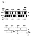
- FIG. 4 shows a part of the various structures on the side of the scanning unit A, the scale M and part of the arrangement of the detector elements within the detector unit D.
- a Abtastreferenzmarken für 200 is provided, the two groups of blocks BA100 - BA400, which in turn consist of the subregions 200u, 200d with different optical properties, which are arranged successively adjacent in the measuring direction x.
- a scale reference mark structure 100 consisting of two groups of blocks BM100 - BM400 and comprising portions 100u, 100d having different optical properties.
- each of the two groups of sample and scale blocks now comprises a plurality of blocks, of which Fig. 4 however, only a part is shown.
- blocks BA100 and BA300 belong to the first group on scan plate A
- blocks BA200 and BA400 belong to the second group.
- the first group is assigned on the scale among other things, the two blocks BM100 and BM300
- the second group includes, among other things, the blocks BM200 and BM400.
- the blocks BA100-BA400 in the scanning booklet or on the scanning plate A are assigned the areal detector elements D100-D400 of the detector unit D in a fixed spatial relationship, i. the block BA100 is associated with the detector element D100, the block BA200 the detector element D200, the block BA300 the detector element D300 and the block BA400 the detector element D400.
- the block BA100 is associated with the detector element D100, the block BA200 the detector element D200, the block BA300 the detector element D300 and the block BA400 the detector element D400.
- the first group of blocks BA100, BA300 on the side of the scanning plate A is in turn formed identically to the associated blocks BM100, BM300; the second group of blocks BA200, BA400 on the side of the scanning plate is again formed complementary to the associated group of blocks BM200, BM400 on the scale, etc ..
- the areas of the detector elements D100, D300 are identical to the areas of the detector elements D200, D400.
- the detector elements associated with the different inputs of the downstream subtraction elements behave identically with regard to their frequency response.
- Analogous to the inventive considerations of the first embodiment is also in the second embodiment of the FIG. 4 provided in each case to interconnect the detector elements of a group of blocks, that is, the detector elements D100 and D300 and the detector elements D200 and D400. From the two groups of detector elements result in the manner shown, the so-called clock reference pulse signal RI T and the push-pull reference pulse signal RI GT .
- the signal RI T again has a maximum at the reference position; the signal RI GT a minimum.
- the signals RI T , RI GT are fed to the two inputs of a subtraction element DIF, where again the difference formation takes place from the two signals RI T , RI GT .
- At the output of the subtraction element DIF results the suitable for further processing reference pulse signal RI Z.
- the difference also ensures, as in the first embodiment, that any stray light effects can be eliminated.
- this embodiment is particularly suitable for optical position measuring with small Bei.ungsiger divergence, since the different groups of blocks or detector elements are arranged relatively close to each other. A possible crosstalk between adjacent blocks or detector elements is excluded due to the low divergence on the lighting side.
- reference mark structures comprised of pure amplitude structures were included.
- the alternately arranged portions of the various structures were either permeable and impermeable or reflective and non-reflective designed.
- a reference pulse signal can be generated according to the invention with sufficiently large graduation periods of the respective structures.
- the sample reference mark structure as a phase structure or as a combined amplitude / phase structure which at the reference position x REF in the plane of the scale reference mark structure 10 ultimately provides the same image or intensity distribution as that in FIG. 2 Accordingly, it must be ensured that an intensity distribution which corresponds to the scale reference mark structure in this block BM2 results in the regions of the block BM2 at the reference position x REF .
- the phase structure required on the scan side must ensure that, at the reference position X REF, an intensity distribution in the scale plane complementary to the scale reference mark structure in those areas results.
- the various detector elements D1 - D3 can then be connected again as shown.
- FIG. 5 shows FIG. 5 in the upper part a section through the scanning A of this embodiment of the optical position measuring device according to the invention.
- the detail shown is part of the sample reference mark structure 300, which is now formed as a combined phase / amplitude structure that provides a certain predetermined intensity distribution in the scale plane.
- the scanning reference mark structure 300 consists of a coarse amplitude structure with permeable and impermeable partial areas 300d, 300u arranged alternately in the measuring direction x.
- phase-shifting structures for example cylindrical lenses, are arranged in a defined manner in the transmissive subregions 300d.
- the phase-shifting structures are formed in the transmissive subregions 300d as webs 300S and gaps 300D which alternate with each other in the measuring direction x.
- FIG. 5 shown section of the now constructed as a phase / amplitude structure sample reference mark pattern 300 is assigned to the reference position x REF a certain part of the scale reference mark pattern 400 on the scale M side.
- This area of the scale M or of the corresponding reference mark structure 400 is shown below the scanning reference mark structure 300.
- This represents about 4 is a section of a block of the scale reference mark structure 400 in which an intensity distribution corresponding to the scale reference mark structure 400 is to be generated.
- the scale reference mark structure 400 consists of alternately arranged reflective subregions 400r and non-reflective subregions 400n in the incident light case. Accordingly, in analogy to the considerations explained above, an intensity maximum at the reference position x REF must result in this block in the reflective subregions 400r, while an intensity minimum is required in the intervening non-reflective subregions 400n.
- phase / amplitude structure now provides exactly such an intensity distribution, as in the lower part of FIG. 5 is shown.
- the resulting intensity distribution of the section of the scanning reference mark structure 300 is shown against the measuring direction x, which generates the required intensity maxima at the reflective subregions 400r of the scale reference mark structure 400.
- a high-contrast reference pulse signal can thus also be produced in the case of smaller pitch periods and a required larger scanning distance in the manner according to the invention.
- the two groups of reference mark structures each comprise more than two blocks with correspondingly arranged subregions.
- This has advantages in terms of soiling resistance, since the contamination of one block is then compensated by the multiplicity of further blocks in the same group. Overall, this results in a more stable reference pulse evaluation. While special detector arrangements with relatively large-area detector elements were used in each case for the reference pulse signal generation in the described exemplary embodiments, it is also conceivable to use so-called detector arrays in the detector unit at this point, as are known for the optical scanning of an incremental graduation track.
- Such detector arrays consist of a multiplicity of radiation-sensitive detector elements arranged immediately adjacent in the measuring direction and having significantly smaller areas; Detector elements which supply in-phase scanning signals are in this case electrically interconnected.
- Such detector arrays can in principle also be used in the context of the present invention. In this case, the detector elements in the detector unit would then each consist of an interconnected number of adjacent individual detector elements of the detector array. An advantage of such a variant would be the reduction in component diversity.
Landscapes
- Physics & Mathematics (AREA)
- General Physics & Mathematics (AREA)
- Optical Transform (AREA)
- Length Measuring Devices By Optical Means (AREA)
- Transmission And Conversion Of Sensor Element Output (AREA)
Claims (11)
- Dispositif de mesure de position optique, pour la détermination de la position relative de deux objets déplaçables l'un par rapport à l'autre dans la direction de mesurage (x), dans lequel un signal d'impulsion de référence (RIz) peut être produit en au moins une position relative définie (xREF), le dispositif de mesure de position comprenant les composants suivantes :a) une graduation (M) avec une structure de repères de référence de graduation (10 ; 100 ; 400), la graduation (M) étant reliée à l'un des deux objets et la structure de repères de référence de graduation (10 ; 100 ; 400) est constituée de n > 2 blocs (BM1, BM2, BM3 ; BM100, BM200, BM300, BM400), disposés côte à côte dans la direction de mesurage (x) et comportant plusieurs régions partielles (10d, 10u ; 100d, 100u ; 400r, 400n) avec différentes caractéristiques optiques, disposées les unes à la suite des autres dans la direction de mesurage (x),b) une unité de balayage (AE) reliée à l'autre objet, et une plaque de balayage (A) avec une structure de repères de référence de balayage (20 ; 200 ; 300), ainsi que plusieurs éléments détecteurs (D1, D2, D3 ; D100, D200, D300, D400), dans lequelb1) la structure de repères de référence de balayage (20 ; 200 ; 300) est également constituée de blocs (BA1, BA2, BA3 ; BA100, BA200, BA300, BA400) disposés côte à côte dans la direction de mesurage (x), etb2) dans lequel au moins un premier groupe de blocs (BA2, BA100, BA300 ; BM2, BM100, BM300) de la structure de repères de référence de balayage (20 ; 200 ; 300) ou de la structure de repères de référence de graduation (10 ; 100 ; 400) est conçu de manière à fournir, à la position de référence (xREF), une répartition d'intensité qui est identique à la structure du premier groupe de blocs correspondant (BA2, BA100, BA300 ; BM2, BM100, BM300) de la structure de repères de référence de balayage ou de graduation (20 ; 200 ; 300 ; 10 ; 100 ; 400), lors d'un éclairage par une source de lumière (LQ) respectivement dans le plan de l'autre structure de repères de référence, et au moins un deuxième groupe de blocs (BA1, BA3, BA200, BA400 ; BM1, BM3, BM200, BM400) de la structure de repères de référence de balayage ou de graduation (20 ; 200 ; 300 ; 10 ; 100 ; 400) fournit une répartition d'intensité qui est complémentaire à la structure des blocs correspondants (BA1, BA3, BA200, BA400 ; BM1, BM3, BM200, BM400) de la structure de repères de référence de balayage ou de graduation (20 ; 200 ; 300 ; 10, 100 ; 400) de la structure de repères de référence de balayage ou de graduation (20 ; 200 ; 300 ; 10 ; 100 ; 400), lors d'un éclairage par une source lumière (LQ) respectivement dans le plan de l'autre structure de repères de référence, où l'un des deux groupes comprend au moins deux blocs (BA1, BA3, BA100, BA300 ; BM1, BM3, BM100, BM300), etb3) un élément détecteur (D1 - D3 ; D100 - D400) est attribué à chaque bloc (BA1 - BA3 ; BA100 - BA400) de la structure de repères de référence de balayage (20 ; 200 ; 300), etb4) les éléments détecteurs (D1 - D3 ; D100, D400) sont branchés de manière à ce que les signaux de sortie (RIT1, RIGT) d'un groupe de blocs soient reliés entre eux, ce pour quoi les éléments détecteurs (D1, D3 ; D100 - D400) de groupes avec plusieurs blocs (BA1, BA3, BA100, BA300 ; BM1, BM3, BM100, BM300) sont connectés entre eux de façon cumulative, de sorte qu'un signal d'impulsion de référence de sortie (RIT1, RIGT) présentant un maximum ou un minimum pour une position relative définie (xREF) des deux objets résulte des signaux de sortie de chaque groupe de blocs.
- Dispositif de mesure de position optique selon la revendication 1, dans lequel la structure de repères de référence de balayage (20 ; 200) est conçue comme une structure d'amplitudes comprenant, dans chaque bloc (BA1 - BA3 ; BA100 - BA400), un agencement de régions partielles (20d, 20u ; 200d, 200u) avec différentes caractéristiques optiques, où, dans un premier groupe de blocs (BA1, BA3 ; BA100, BA300), l'agencement des régions partielles (20d, 20u ; 200d, 200u) est identique à l'agencement des régions partielles (10d, 10u ; 100d, 100u) dans les blocs correspondants (BM1, BM3 ; BM100, BM300) de la structure de repères de référence de graduation (10 ; 100), et où, dans au moins un deuxième groupe de blocs (BA2 ; BA200, BA400), l'agencement des régions partielles (20d, 20u ; 200d, 200u) est complémentaire à l'agencement des régions partielles (10d, 10u ; 100d, 100u) dans les blocs correspondants (BM2 ; BM200, BM400) de la structure de repères de référence de graduation (10 ; 100).
- Dispositif de mesure de position optique selon la revendication 1, dans lequel la structure de repères de référence de balayage (300) est conçue comme une structure de phases ou comme une structure d'amplitudes et de phases combinée.
- Dispositif de mesure de position optique selon la revendication 3, dans lequel la structure de repères de référence de balayage (300) conçue comme une structure d'amplitudes et de phases combinée (300) est constituée de régions partielles (300d, 300u) transparentes et opaques, et des structures à décalage de phase sont agencées dans les régions partielles transparentes (300u).
- Dispositif de mesure de position optique selon la revendication 1, dans lequel les signaux d'impulsion de référence de sortie (RIT1, RIGT) des deux groupes de blocs sont connectés en différence.
- Dispositif de mesure de position optique selon la revendication 5, dans lequel les signaux d'impulsion de référence de sortie (RIT1, RIGT) sont appliqués aux entrées d'un élément de formation de différence (DIF).
- Dispositif de mesure de position optique selon la revendication 1, dans lequel plusieurs régions partielles conçues optiquement transparentes ou opaques sont agencées dans chaque bloc (BM1 - BM3 ; BM100 - BM400) de la structure de repères de référence de graduation (10 ; 100 ; 400) et/ou dans chaque bloc (BA1 - BA3 ; BA100 - BA400) de la structure de repères de référence de balayage (20 ; 200).
- Dispositif de mesure de position selon la revendication 1, dans lequel plusieurs régions partielles optiquement réfléchissantes ou non-réfléchissantes sont agencées dans chaque bloc de la structure de repères de référence de graduation et/ou dans chaque bloc de la structure de repères de référence de balayage.
- Dispositif de mesure de position optique selon la revendication 1, dans lequel les surfaces des éléments détecteurs (D1 - D3 ; D100 - D400) sont conçues sensiblement plus grandes que les surfaces des blocs correspondants (BM1 - BM3 ; BM100 - BM400 ; BA1 - BA3 ; BA100 - BA400) des structures de repères de référence de graduation et de balayage (10 ; 100 ; 20 ; 200).
- Dispositif de mesure de position optique selon la revendication 1, dans lequel il est prévu un nombre pair de blocs des deux groupes des structures de repères de référence de graduation et de balayage, et les surfaces de tous les blocs des structures de repères de référence de graduation et de balayage sont choisies identiques.
- Dispositif de mesure de position selon la revendication 1, dans lequel il est prévu un nombre impair de blocs des deux groupes des structures de repères de référence de graduation et de balayage, et la somme des surfaces du premier groupe est choisie identique à la somme des surfaces du deuxième groupe des structures de repères de référence de graduation et de balayage.
Applications Claiming Priority (4)
| Application Number | Priority Date | Filing Date | Title |
|---|---|---|---|
| DE19853295 | 1998-11-19 | ||
| DE19853295 | 1998-11-19 | ||
| DE19936181 | 1999-07-31 | ||
| DE19936181A DE19936181A1 (de) | 1998-11-19 | 1999-07-31 | Optische Positionsmeßeinrichtung |
Publications (4)
| Publication Number | Publication Date |
|---|---|
| EP1003012A2 EP1003012A2 (fr) | 2000-05-24 |
| EP1003012A3 EP1003012A3 (fr) | 2001-03-07 |
| EP1003012B1 EP1003012B1 (fr) | 2009-05-13 |
| EP1003012B3 true EP1003012B3 (fr) | 2011-04-20 |
Family
ID=26050241
Family Applications (1)
| Application Number | Title | Priority Date | Filing Date |
|---|---|---|---|
| EP99121779A Expired - Lifetime EP1003012B3 (fr) | 1998-11-19 | 1999-11-03 | Système optique pour la mesure de position |
Country Status (3)
| Country | Link |
|---|---|
| US (1) | US6175414B1 (fr) |
| EP (1) | EP1003012B3 (fr) |
| JP (1) | JP4358387B2 (fr) |
Families Citing this family (23)
| Publication number | Priority date | Publication date | Assignee | Title |
|---|---|---|---|---|
| DE19854733A1 (de) * | 1998-11-27 | 2000-05-31 | Heidenhain Gmbh Dr Johannes | Abtasteinheit einer Positionsmeßeinrichtung |
| EP1028309B1 (fr) * | 1999-02-04 | 2003-04-16 | Dr. Johannes Heidenhain GmbH | Codeur optique |
| US6492637B1 (en) * | 1999-05-10 | 2002-12-10 | Citizen Watch Co., Ltd. | Dimension measuring device |
| US6401351B1 (en) | 2000-06-09 | 2002-06-11 | Trilogy Technologies, Inc. | Sensor system for determining relative displacement of an object using a flexible retractable activation member |
| US6351994B1 (en) | 2000-06-09 | 2002-03-05 | Trilogy Technologies, Inc. | Sensor system for determining relative displacement of an object using an activation member |
| US7145126B2 (en) * | 2004-03-16 | 2006-12-05 | Wai-Hon Lee | Optical position encoder device using incoherent light source |
| JP4498024B2 (ja) * | 2004-06-15 | 2010-07-07 | キヤノン株式会社 | 光学式エンコーダ |
| EP1825226A4 (fr) * | 2004-12-15 | 2009-02-18 | Aimbridge Pty Ltd | Potentiometre optique et ensemble a levier de commande |
| EP1949037A1 (fr) * | 2005-10-28 | 2008-07-30 | Aimbridge Pty. Ltd. | Potentiometre optique a compensation de derive de temperature |
| US7476843B2 (en) * | 2005-12-23 | 2009-01-13 | Delphi Technologies, Inc. | Method for determining the position of a first moving component relative to a second component and device for applying said method |
| DE102006024579B4 (de) * | 2006-05-18 | 2016-09-29 | Dr. Johannes Heidenhain Gmbh | Vorrichtung zur Bestimmung der Position eines entlang mindestens einer Verschieberichtung bewegbaren Objektes |
| US8011112B2 (en) * | 2006-12-07 | 2011-09-06 | Leica Geosystems Ag | Method and apparatus for determining positions |
| US20080156973A1 (en) * | 2006-12-29 | 2008-07-03 | Weng Fei Wong | Photosensor array for optical encoder |
| US7973941B2 (en) * | 2007-07-24 | 2011-07-05 | Mitutoyo Corporation | Reference signal generating configuration for an interferometric miniature grating encoder readhead using fiber optic receiver channels |
| US20090027692A1 (en) * | 2007-07-24 | 2009-01-29 | Mitutoyo Corporation | Reference signal generating configuration for an interferometric miniature grating encoder readhead using fiber optic receiver channels |
| US7965393B2 (en) | 2007-07-24 | 2011-06-21 | Mitutoyo Corporation | Reference signal generating configuration for an interferometric miniature grating encoder readhead using fiber optic receiver channels |
| DE102007056612A1 (de) * | 2007-11-23 | 2009-05-28 | Dr. Johannes Heidenhain Gmbh | Optische Positionsmesseinrichtung |
| WO2012103870A1 (fr) | 2011-01-31 | 2012-08-09 | Witeg Labortechnik Gmbh | Distributeur pour flacons pourvu d'un affichage numérique de volume |
| US20140002642A1 (en) | 2012-06-15 | 2014-01-02 | Elmar SWIEGOT | Absolute position detection |
| DE102012018458A1 (de) * | 2012-09-19 | 2014-03-20 | Prema Semiconductor Gmbh | Vorrichtung zur Erfassung von Winkel- oder Lageänderungen |
| JP6087722B2 (ja) * | 2013-05-16 | 2017-03-01 | 株式会社ミツトヨ | 原点信号発生装置及び原点信号発生システム |
| JP2015160398A (ja) * | 2014-02-28 | 2015-09-07 | セイコーエプソン株式会社 | 液体吐出装置、および、液体吐出装置の偏位量検出方法 |
| DE102020201198B4 (de) * | 2020-01-31 | 2023-08-17 | Carl Zeiss Industrielle Messtechnik Gmbh | Verfahren und Anordnung zum Ermitteln einer Position und/oder einer Ausrichtung eines beweglichen Objekts einer Anordnung von Objekten |
Family Cites Families (14)
| Publication number | Priority date | Publication date | Assignee | Title |
|---|---|---|---|---|
| BE756467A (fr) * | 1969-09-24 | 1971-03-22 | Philips Nv | Dispositif pour aligner des objets, comportant une source lumineuse, unsysteme de detection photosensible et deux porteurs pour configuration |
| US4691101A (en) | 1985-06-19 | 1987-09-01 | Hewlett-Packard Company | Optical positional encoder comprising immediately adjacent detectors |
| DE3536466A1 (de) * | 1985-10-12 | 1987-04-16 | Bodenseewerk Geraetetech | Nullimpulserzeuger zur erzeugung eines impulses bei erreichen einer vorgegebenen lage eines traegers |
| JPS62132104A (ja) * | 1985-12-04 | 1987-06-15 | Futaba Corp | 測長装置 |
| DE3611204A1 (de) | 1986-04-04 | 1987-10-15 | Heidenhain Gmbh Dr Johannes | Messeinrichtung |
| DE3844705C2 (fr) * | 1987-09-30 | 1992-06-17 | Kabushiki Kaisha Okuma Tekkosho, Nagoya, Aichi, Jp | |
| DE3908254A1 (de) | 1989-03-14 | 1990-09-20 | Heidenhain Gmbh Dr Johannes | Positionsmesseinrichtung |
| EP0421024B1 (fr) | 1989-10-06 | 1992-12-09 | Dr. Johannes Heidenhain GmbH | Dispositif photoélectrique de mesure de position |
| US5065017A (en) * | 1990-04-20 | 1991-11-12 | Hoech Robert W | Zero mark for optical encoder using stator mask patterns and rotor patterns |
| GB2288015B (en) | 1994-03-31 | 1997-11-19 | Mitutoyo Corp | Optical encoder having a photodiode array that serves both for a light detector and an index scale |
| DE4420551A1 (de) * | 1994-06-15 | 1995-12-21 | Vdo Schindling | Positionsgeber |
| DE19530904B4 (de) * | 1995-08-23 | 2005-08-04 | Siemens Ag | Vorrichtung zur Erfassung einer Position eines sich relativ zu einer Basis rotatorisch oder translatorisch bewegenden Objektes |
| DE19726935B4 (de) | 1997-06-25 | 2014-06-12 | Dr. Johannes Heidenhain Gmbh | Optische Positionsmeßeinrichtung |
| AT410485B (de) * | 1997-07-30 | 2003-05-26 | Rsf Elektronik Gmbh | Positionsmesseinrichtung |
-
1999
- 1999-11-03 EP EP99121779A patent/EP1003012B3/fr not_active Expired - Lifetime
- 1999-11-09 JP JP31871099A patent/JP4358387B2/ja not_active Expired - Fee Related
- 1999-11-18 US US09/443,238 patent/US6175414B1/en not_active Expired - Lifetime
Also Published As
| Publication number | Publication date |
|---|---|
| JP4358387B2 (ja) | 2009-11-04 |
| EP1003012A2 (fr) | 2000-05-24 |
| EP1003012B1 (fr) | 2009-05-13 |
| EP1003012A3 (fr) | 2001-03-07 |
| JP2000155010A (ja) | 2000-06-06 |
| US6175414B1 (en) | 2001-01-16 |
Similar Documents
| Publication | Publication Date | Title |
|---|---|---|
| EP1003012B3 (fr) | Système optique pour la mesure de position | |
| EP0509979B1 (fr) | Dispositif de mesure de positions photo-électronique | |
| EP1081457B1 (fr) | Dispositif optique de mesure de la position | |
| EP0896206B1 (fr) | Unité de lecture pour dispositif optique de mesure de position | |
| EP2149036B1 (fr) | Dispositif de mesure de position optique | |
| DE19748802B4 (de) | Optische Positionsmeßeinrichtung | |
| EP1111345B1 (fr) | Dispositif de mesure de position avec une piste incrementielle avec deux graduations de période differente | |
| EP0160811B1 (fr) | Dispositif de mesure photo-électrique | |
| EP1923673B1 (fr) | Dispositif de mesure de position | |
| EP1407231B1 (fr) | Dispositif de mesure de position | |
| DE102008007319A1 (de) | Optische Positionsmesseinrichtung | |
| EP0669518B1 (fr) | Dispositif pour générer des signaux dépendants de la position | |
| DE60033075T3 (de) | Kodierer | |
| DE19726935B4 (de) | Optische Positionsmeßeinrichtung | |
| EP1271107A1 (fr) | Dispositif de mesure de position | |
| DE102004010566A1 (de) | Tastkopf für ein Koordinatenmessgerät | |
| EP1050742B1 (fr) | Unité de balayage pour un dispositif optique de mesure de position | |
| EP2878930B1 (fr) | Dispositif de mesure de position | |
| EP1377799B1 (fr) | Systeme de mesure de position optique | |
| DE19936181A1 (de) | Optische Positionsmeßeinrichtung | |
| DE10043828B4 (de) | Abtasteinheit für eine optische Positionsmesseinrichtung | |
| DE10346380B4 (de) | Positionsmesseinrichtung | |
| EP3936830B1 (fr) | Dispositif optique de mesure de la position | |
| DE202005002622U1 (de) | Optische Positionsmesseinrichtung | |
| DE102015225272A1 (de) | Optische Positionsmesseinrichtung |
Legal Events
| Date | Code | Title | Description |
|---|---|---|---|
| PUAI | Public reference made under article 153(3) epc to a published international application that has entered the european phase |
Free format text: ORIGINAL CODE: 0009012 |
|
| AK | Designated contracting states |
Kind code of ref document: A2 Designated state(s): AT BE CH CY DE DK ES FI FR GB GR IE IT LI LU MC NL PT SE |
|
| AX | Request for extension of the european patent |
Free format text: AL;LT;LV;MK;RO;SI |
|
| PUAL | Search report despatched |
Free format text: ORIGINAL CODE: 0009013 |
|
| AK | Designated contracting states |
Kind code of ref document: A3 Designated state(s): AT BE CH CY DE DK ES FI FR GB GR IE IT LI LU MC NL PT SE |
|
| AX | Request for extension of the european patent |
Free format text: AL;LT;LV;MK;RO;SI |
|
| RIC1 | Information provided on ipc code assigned before grant |
Free format text: 7G 01B 11/02 A, 7G 01D 5/36 B |
|
| 17P | Request for examination filed |
Effective date: 20010907 |
|
| AKX | Designation fees paid |
Free format text: AT BE CH CY DE DK ES FI FR GB GR IE IT LI LU MC NL PT SE |
|
| 17Q | First examination report despatched |
Effective date: 20071019 |
|
| GRAP | Despatch of communication of intention to grant a patent |
Free format text: ORIGINAL CODE: EPIDOSNIGR1 |
|
| GRAS | Grant fee paid |
Free format text: ORIGINAL CODE: EPIDOSNIGR3 |
|
| GRAA | (expected) grant |
Free format text: ORIGINAL CODE: 0009210 |
|
| AK | Designated contracting states |
Kind code of ref document: B1 Designated state(s): AT BE CH CY DE DK ES FI FR GB GR IE IT LI LU MC NL PT SE |
|
| REG | Reference to a national code |
Ref country code: GB Ref legal event code: FG4D Free format text: NOT ENGLISH |
|
| REG | Reference to a national code |
Ref country code: CH Ref legal event code: EP |
|
| REG | Reference to a national code |
Ref country code: IE Ref legal event code: FG4D |
|
| REF | Corresponds to: |
Ref document number: 59915025 Country of ref document: DE Date of ref document: 20090625 Kind code of ref document: P |
|
| PG25 | Lapsed in a contracting state [announced via postgrant information from national office to epo] |
Ref country code: PT Free format text: LAPSE BECAUSE OF FAILURE TO SUBMIT A TRANSLATION OF THE DESCRIPTION OR TO PAY THE FEE WITHIN THE PRESCRIBED TIME-LIMIT Effective date: 20090913 Ref country code: FI Free format text: LAPSE BECAUSE OF FAILURE TO SUBMIT A TRANSLATION OF THE DESCRIPTION OR TO PAY THE FEE WITHIN THE PRESCRIBED TIME-LIMIT Effective date: 20090513 Ref country code: ES Free format text: LAPSE BECAUSE OF FAILURE TO SUBMIT A TRANSLATION OF THE DESCRIPTION OR TO PAY THE FEE WITHIN THE PRESCRIBED TIME-LIMIT Effective date: 20090824 |
|
| NLV1 | Nl: lapsed or annulled due to failure to fulfill the requirements of art. 29p and 29m of the patents act | ||
| PG25 | Lapsed in a contracting state [announced via postgrant information from national office to epo] |
Ref country code: SE Free format text: LAPSE BECAUSE OF FAILURE TO SUBMIT A TRANSLATION OF THE DESCRIPTION OR TO PAY THE FEE WITHIN THE PRESCRIBED TIME-LIMIT Effective date: 20090813 Ref country code: NL Free format text: LAPSE BECAUSE OF FAILURE TO SUBMIT A TRANSLATION OF THE DESCRIPTION OR TO PAY THE FEE WITHIN THE PRESCRIBED TIME-LIMIT Effective date: 20090513 |
|
| REG | Reference to a national code |
Ref country code: IE Ref legal event code: FD4D |
|
| PG25 | Lapsed in a contracting state [announced via postgrant information from national office to epo] |
Ref country code: IE Free format text: LAPSE BECAUSE OF FAILURE TO SUBMIT A TRANSLATION OF THE DESCRIPTION OR TO PAY THE FEE WITHIN THE PRESCRIBED TIME-LIMIT Effective date: 20090513 Ref country code: DK Free format text: LAPSE BECAUSE OF FAILURE TO SUBMIT A TRANSLATION OF THE DESCRIPTION OR TO PAY THE FEE WITHIN THE PRESCRIBED TIME-LIMIT Effective date: 20090513 |
|
| PLBE | No opposition filed within time limit |
Free format text: ORIGINAL CODE: 0009261 |
|
| 26N | No opposition filed |
Effective date: 20100216 |
|
| BERE | Be: lapsed |
Owner name: DR. JOHANNES HEIDENHAIN G.M.B.H. Effective date: 20091130 |
|
| PG25 | Lapsed in a contracting state [announced via postgrant information from national office to epo] |
Ref country code: MC Free format text: LAPSE BECAUSE OF NON-PAYMENT OF DUE FEES Effective date: 20091130 |
|
| REG | Reference to a national code |
Ref country code: CH Ref legal event code: PL |
|
| REG | Reference to a national code |
Ref country code: FR Ref legal event code: ST Effective date: 20100730 |
|
| PLCP | Request for limitation filed |
Free format text: ORIGINAL CODE: EPIDOSNLIM1 |
|
| PLCQ | Request for limitation of patent found admissible |
Free format text: ORIGINAL CODE: 0009231 |
|
| PG25 | Lapsed in a contracting state [announced via postgrant information from national office to epo] |
Ref country code: LI Free format text: LAPSE BECAUSE OF NON-PAYMENT OF DUE FEES Effective date: 20091130 Ref country code: GR Free format text: LAPSE BECAUSE OF FAILURE TO SUBMIT A TRANSLATION OF THE DESCRIPTION OR TO PAY THE FEE WITHIN THE PRESCRIBED TIME-LIMIT Effective date: 20090814 Ref country code: FR Free format text: LAPSE BECAUSE OF NON-PAYMENT OF DUE FEES Effective date: 20091130 Ref country code: CH Free format text: LAPSE BECAUSE OF NON-PAYMENT OF DUE FEES Effective date: 20091130 Ref country code: BE Free format text: LAPSE BECAUSE OF NON-PAYMENT OF DUE FEES Effective date: 20091130 |
|
| LIM1 | Request for limitation found admissible |
Free format text: SEQUENCE NO: 1; FILED AFTER OPPOSITION PERIOD Filing date: 20100923 |
|
| PLCO | Limitation procedure: reply received to communication from examining division + time limit |
Free format text: ORIGINAL CODE: EPIDOSNLIR3 |
|
| PLCR | Communication despatched that request for limitation of patent was allowed |
Free format text: ORIGINAL CODE: 0009245 |
|
| PG25 | Lapsed in a contracting state [announced via postgrant information from national office to epo] |
Ref country code: AT Free format text: LAPSE BECAUSE OF NON-PAYMENT OF DUE FEES Effective date: 20091103 |
|
| PLCN | Payment of fee for limitation of patent |
Free format text: ORIGINAL CODE: EPIDOSNRAL3 |
|
| PUAM | (expected) publication of b3 document |
Free format text: ORIGINAL CODE: 0009410 |
|
| STAA | Information on the status of an ep patent application or granted ep patent |
Free format text: STATUS: THE PATENT HAS BEEN LIMITED |
|
| PG25 | Lapsed in a contracting state [announced via postgrant information from national office to epo] |
Ref country code: IT Free format text: LAPSE BECAUSE OF FAILURE TO SUBMIT A TRANSLATION OF THE DESCRIPTION OR TO PAY THE FEE WITHIN THE PRESCRIBED TIME-LIMIT Effective date: 20090513 |
|
| REG | Reference to a national code |
Ref country code: DE Ref legal event code: 8505 |
|
| REG | Reference to a national code |
Ref country code: DE Ref legal event code: R097 Ref document number: 59915025 Country of ref document: DE Ref country code: DE Ref legal event code: R056 Ref document number: 59915025 Country of ref document: DE |
|
| PG25 | Lapsed in a contracting state [announced via postgrant information from national office to epo] |
Ref country code: LU Free format text: LAPSE BECAUSE OF NON-PAYMENT OF DUE FEES Effective date: 20091103 |
|
| REG | Reference to a national code |
Ref country code: CH Ref legal event code: AEN Free format text: BESCHRAENKUNGANTRAG GUTGEHEISSEN |
|
| PG25 | Lapsed in a contracting state [announced via postgrant information from national office to epo] |
Ref country code: CY Free format text: LAPSE BECAUSE OF FAILURE TO SUBMIT A TRANSLATION OF THE DESCRIPTION OR TO PAY THE FEE WITHIN THE PRESCRIBED TIME-LIMIT Effective date: 20090513 |
|
| PGFP | Annual fee paid to national office [announced via postgrant information from national office to epo] |
Ref country code: GB Payment date: 20151118 Year of fee payment: 17 |
|
| PGFP | Annual fee paid to national office [announced via postgrant information from national office to epo] |
Ref country code: DE Payment date: 20161121 Year of fee payment: 18 |
|
| GBPC | Gb: european patent ceased through non-payment of renewal fee |
Effective date: 20161103 |
|
| PG25 | Lapsed in a contracting state [announced via postgrant information from national office to epo] |
Ref country code: GB Free format text: LAPSE BECAUSE OF NON-PAYMENT OF DUE FEES Effective date: 20161103 |
|
| REG | Reference to a national code |
Ref country code: DE Ref legal event code: R119 Ref document number: 59915025 Country of ref document: DE |
|
| PG25 | Lapsed in a contracting state [announced via postgrant information from national office to epo] |
Ref country code: DE Free format text: LAPSE BECAUSE OF NON-PAYMENT OF DUE FEES Effective date: 20180602 |