EP1002890A2 - Leitvorrichtung für Faser in Form einer Matte zum Beschicken einer Karde - Google Patents
Leitvorrichtung für Faser in Form einer Matte zum Beschicken einer Karde Download PDFInfo
- Publication number
- EP1002890A2 EP1002890A2 EP99203663A EP99203663A EP1002890A2 EP 1002890 A2 EP1002890 A2 EP 1002890A2 EP 99203663 A EP99203663 A EP 99203663A EP 99203663 A EP99203663 A EP 99203663A EP 1002890 A2 EP1002890 A2 EP 1002890A2
- Authority
- EP
- European Patent Office
- Prior art keywords
- mat
- roller
- fibres
- carder
- guide means
- Prior art date
- Legal status (The legal status is an assumption and is not a legal conclusion. Google has not performed a legal analysis and makes no representation as to the accuracy of the status listed.)
- Withdrawn
Links
Images



Classifications
-
- D—TEXTILES; PAPER
- D01—NATURAL OR MAN-MADE THREADS OR FIBRES; SPINNING
- D01G—PRELIMINARY TREATMENT OF FIBRES, e.g. FOR SPINNING
- D01G23/00—Feeding fibres to machines; Conveying fibres between machines
- D01G23/02—Hoppers; Delivery shoots
-
- D—TEXTILES; PAPER
- D01—NATURAL OR MAN-MADE THREADS OR FIBRES; SPINNING
- D01G—PRELIMINARY TREATMENT OF FIBRES, e.g. FOR SPINNING
- D01G15/00—Carding machines or accessories; Card clothing; Burr-crushing or removing arrangements associated with carding or other preliminary-treatment machines
- D01G15/02—Carding machines
- D01G15/12—Details
- D01G15/40—Feeding apparatus
- D01G15/42—Feeding from laps
Definitions
- the present invention relates to supply to carders, in which fibrous material in a thin layer is worked by a series of surfaces which are provided with a multiplicity of tips with a variety of shapes, inclinations and rigidities, and are driven by motion relative to one another, by which the fibrous material is opened up into the form of individual fibres, the particles of dirt are eliminated, the fibres are mingled with one another, and a strip of non-twisted fibres is formed, to be conveyed to the subsequent processing stages.
- the untreated material 1 is obtained in general from an opener, not shown in the figure, and consists of flock fibres. It is conveyed by pneumatic transport in an air current, and is accumulated in the end part 2 of the descending duct 3 for intake of the fibres. The transport air is discharged from the apertures 4; as the fibrous material is deposited in the end part 2, it covers these apertures, and increases the pressure in the duct 3. Monitoring of the pressure value in the upper duct makes it possible to detect the level of filling of the end chamber or part 2. On the basis of this level of filling, there is regulation of the processing, and conveyance of flock fibres from the preceding set of openers.
- the flow of fibres, conveyed by the opener unit upstream to the carder downstream, is preferably distributed to the carders which have their ducts 3 least filled, and which thus provide a lower load loss for the flow of fibres.
- the supply cylinder 5 Downstream from the end part 2, there is disposed the supply cylinder 5, which supplies the flock fibres to the breaker cylinder 6, which breaks up the material.
- the two cylinders operate with coherent rotation, in order to transfer the material into the duct 7 beneath.
- the air current in order to maintain the pressure in the lower chanter 8 at the end of the duct 7 is supplied by a blower 10, which provides an air flow which is tangential relative to the breaker cylinder 6, and is then discharged from the apertures 11.
- a pressure switch which controls the speed of rotation of the roller 5, such as to regulate the density of the fibres which are contained in the chamber 8, and form the mat supplied to the carder.
- the base of the second descending duct 7 is equivalent to conventional storage of fibres in a silo, in which the density of the fibres is controlled and regulated by pneumatic effect.
- the machine is provided with a supply roller 16, which presses and controls the mat against the supply plate 17, and supplies a strip of mat to the actual carder.
- the first carding stage is carried out by means of the opener cylinder 18, which is commonly known as the "briseur".
- the transverse dimension of the mat supplied is compatible with that of the processing cylinders of the carder; for carders of the cotton-industry type, this transverse dimension is in general between 0.7 and 1.5 m, depending on the models, and it is essential that this mat is well distributed in terms of thickness and density along its entire width, such that the strip produced by the carder is worked homogeneously in the transverse direction.
- the supply system described hitherto has some problems. Significant amongst these is considerable difficulty in starting up, when a new batch of fibres is started, or after a stoppage for maintenance of the upper accumulation system, or when the continuity of the supply of fibres is interrupted. In these cases, the slide 14 is empty of fibres, and the continuity of the mat 15 must be reconstituted with the new fibres which begin to be released by the lobed rollers 13, which have been re-started, after the ducts and storage units above have been supplied with the fibres of the new batch.
- the new fibres are released into a mat 15 by the two rollers 13, initially at a low linear speed, in general of 0.1 to 0.5m per minute, and flow downwards along the slide 14, with a lap which has an inflated shape which expands upwards. This speed is then gradually increased to the steady-state value, which in general is between 2 and 4m per minute.
- the phenomenon of inflation of the material at the front of the lap is caused by a resilient effect of the fibres, which, after the compression sustained in the gap between the lobed rollers 13, tend to resume their natural preceding state, and to decrease their apparent density, expanding and becoming softer.
- the lap has time to expand freely until it assumes excessive thicknesses, which does not allow the roller 16 to capture and control the lap correctly: the lap can in fact tend to surmount this roller, at least in its upper part.
- the phenomenon is further influenced by the fact that when the system is restarted, the pneumatic conditions of the accumulation silos and ducts above are in general adverse, and not at the steady state, with fluctuations of the density of the body of fibres which is released by the rollers 13.
- the present invention relates more particularly to a system for starting the supply to the opening cylinders or briseur of a carder, which requires reduced use of workforce, prevents accidents, and reduces the dead times for starting up.
- the starting system according to the invention is divided up into a device, the substantial characteristics of which are defined in claim 1, and the preferred embodiments of which are defined in the dependent claims.
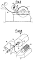
- the end part of the slide 14 for starting conveyance of the fibres in the form of a mat is superimposed by an element to restrain the lap of the mat, for example a restraint wall 20 which delimits the height available for passage of the mat.
- this wall consists of a flat plate 20, the width of which is equivalent to that of the slide 14, and is shaped in the form of a J in its lower end towards the roller 16.
- this plate is supported by the structure of the slide 14, and in particular by its vertical flanks 21 which restrain the mat, and end in two trapezoidal uprights 22.
- the wall 20 On both sides of the wall 20, there are secured several pairs of securing plates or lugs 23, which are provided with through apertures 24.
- the uprights 22 there are provided pairs of through apertures, at distances compatible with those of the pairs of apertures 24.
- the lower aperture 25 has a circular cross-section for passage of its screw 27 to be screwed onto the nut 28, and secures the position of the end of the J, without interfering with the supply roller 16;
- the upper apertures 29 are produced in the shape of a curved slot for passage of the screw 30 and securing of the latter to the nut 31. Modification of the securing in the slots 29 permits regulation of the corresponding gradient of the wall 20, relative to the slide 14, for constriction of the mat 15 towards the roller 16, thus preventing the mat from surmounting the said roller.
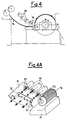
- the restraint element which superimposes the end part of the slide 14 consists of a roller 40 with a horizontal axis.
- this roller is produced with a length which is equivalent to the width of the slide 14, is mounted on a shaft 41, and is rendered idle relative to the latter by means of bearings 42.
- the height of this roller can be adjusted independently from the supply roller, in order to adapt to any thickness of the mat 15.
- the roller is supported similarly to the wall 20, by the structure of the slide 14, and in particular by its vertical walls 21, for restraint of the mat, which end in two trapezoidal uprights 22.
- the structure of the slide 14 and in particular by its vertical walls 21, for restraint of the mat, which end in two trapezoidal uprights 22.
- two apertures in the form of an elongate slot 43 for regulation of the corresponding distance of the shaft 41 of the roller 40, relative to the slide 14, and constriction of the mat 15, without creating interference with the roller 16.
- the shaft 41 is secured and locked in the regulation position by known means, for example by threading 44 of its ends, and locking by means of plates, nuts and spacers in the slots 43.
- the roller 40 can also be controlled in rotation.
- the roller 40 can be controlled by the supply roller 16, by means of a toothed-belt kinematic mechanism 46.
- the fibrous material is provided with action of conveying towards the gripping point.
- the restraint element which superimposes the end part of the slide 14 is produced by means of a plurality of rollers 50 with a horizontal axis, which are similar to the roller 40, and are disposed in series, in order to obtain progressive reduction of the height available for passage of the mat.
- the series of the rollers 50 can thus be regulated both in terms of distance of the individual rollers, and the gradient of their assembly for restraint, relative to the slide 14.
- in the uprights 22a there are provided two apertures with a vertical slot 51, for regulation of the corresponding distance of the shaft 52 of the rollers 50, relative to the slide 14.
- the securing system for the shafts can be altogether similar to that shown in figure 3a.
- rollers 50 can also be rotated in order to convey the fibres towards the gripping point.
- the device according to the present invention makes it possible to eliminate the disadvantages described, both during the starting stage, and in normal use.
- the lap of the new mat which descends the slide 14 is progressively constrained by the restraint element, both by means of the wall and rollers, in order to restrict inflation of the mat, and to channel it between the roller 16 and the plate 17.
- the operators therefore do not need to intervene manually in order to compress the front of the lap of the new fibres beneath the roller 16, with all the associated disadvantages, particularly if many carders must be started up at once.
Landscapes
- Engineering & Computer Science (AREA)
- Textile Engineering (AREA)
- Preliminary Treatment Of Fibers (AREA)
- Table Devices Or Equipment (AREA)
Applications Claiming Priority (2)
| Application Number | Priority Date | Filing Date | Title |
|---|---|---|---|
| ITMI982506 IT1303835B1 (it) | 1998-11-19 | 1998-11-19 | Mezzo di guida perfezionato delle fibre in materassino alimentatead una carda |
| ITMI982506 | 1998-11-19 |
Publications (2)
| Publication Number | Publication Date |
|---|---|
| EP1002890A2 true EP1002890A2 (de) | 2000-05-24 |
| EP1002890A3 EP1002890A3 (de) | 2001-04-18 |
Family
ID=11381088
Family Applications (1)
| Application Number | Title | Priority Date | Filing Date |
|---|---|---|---|
| EP99203663A Withdrawn EP1002890A3 (de) | 1998-11-19 | 1999-11-05 | Leitvorrichtung für Faser in Form einer Matte zum Beschicken einer Karde |
Country Status (2)
| Country | Link |
|---|---|
| EP (1) | EP1002890A3 (de) |
| IT (1) | IT1303835B1 (de) |
Family Cites Families (5)
| Publication number | Priority date | Publication date | Assignee | Title |
|---|---|---|---|---|
| DE2004394C3 (de) * | 1970-01-31 | 1981-07-02 | Hergeth KG Maschinenfabrik und Apparatebau, 4408 Dülmen | Vorrichtung zum Regeln der Zufuhr von Fasergut beim Speisen von Karden u.dgl. |
| CH623361A5 (de) * | 1977-07-18 | 1981-05-29 | Rieter Ag Maschf | |
| US4414710A (en) * | 1978-11-09 | 1983-11-15 | Bolen George F | Textile carding machine feed assembly and method |
| DE3205776C3 (de) * | 1982-02-18 | 1996-06-13 | Truetzschler Gmbh & Co Kg | Verfahren und Vorrichtung zur Regulierung der einer Krempel zuzuführenden Fasermenge |
| DE4200394B4 (de) * | 1991-03-19 | 2004-12-02 | Trützschler GmbH & Co KG | Vorrichtung zum Reinigen und Öffnen von in Flockenform befindlichem Fasergut z. B. Baumwolle, synthetischem Fasergut u. dgl. |
-
1998
- 1998-11-19 IT ITMI982506 patent/IT1303835B1/it active
-
1999
- 1999-11-05 EP EP99203663A patent/EP1002890A3/de not_active Withdrawn
Also Published As
| Publication number | Publication date |
|---|---|
| IT1303835B1 (it) | 2001-03-01 |
| ITMI982506A1 (it) | 2000-05-19 |
| EP1002890A3 (de) | 2001-04-18 |
Similar Documents
| Publication | Publication Date | Title |
|---|---|---|
| US4219289A (en) | Arrangement for loading a card | |
| CN1020932C (zh) | 一种纤维加工设备 | |
| CN110318124B (zh) | 用于梳棉机的进料装置 | |
| EP1004693B1 (de) | Vorrichtung zum Vorbereiten und Oeffnen von Faserflocken geliefert zu einer Karde | |
| US5205018A (en) | Apparatus for making a lap from textile fibers | |
| US4539728A (en) | Cards | |
| US3029477A (en) | Automatic carding plant | |
| US4701981A (en) | Apparatus for pneumatically feeding a plurality of carding machines | |
| US4262390A (en) | Roller gin and feed system incorporating the same | |
| US2219285A (en) | Apparatus and method for nodulating fibers | |
| US3192571A (en) | Fiber processing system | |
| US4129924A (en) | Apparatus for separating card strips during carding of fibrous materials | |
| EP1002890A2 (de) | Leitvorrichtung für Faser in Form einer Matte zum Beschicken einer Karde | |
| US4240182A (en) | Arrangement for opening textile fiber bales | |
| US3101504A (en) | Cleaning device for yarn carrying rotary cylinders of textile machines | |
| US4528723A (en) | Apparatus for feeding fibrous material in the form of flocks to processing machines | |
| US6880322B1 (en) | Opening roller housing for an open-end spinning device, device for an opening roller housing and procedure for modernizing spinning devices | |
| US6058568A (en) | Fiber-guiding wedge for carders | |
| US4432200A (en) | Method for the suction removal of thread breaks and thread suction apparatus | |
| USRE31802E (en) | Roller gin and feed system incorporating the same | |
| CN213417236U (zh) | 一种双气压振动气动棉箱 | |
| US6061878A (en) | Feeding device for fiber mats in flat carders | |
| US4563794A (en) | Self-cleaning roller gin | |
| CN120575386B (zh) | 纤维毡成品质量控制系统 | |
| US5911676A (en) | Low-speed trash belt for open-end spinning machine and method |
Legal Events
| Date | Code | Title | Description |
|---|---|---|---|
| PUAI | Public reference made under article 153(3) epc to a published international application that has entered the european phase |
Free format text: ORIGINAL CODE: 0009012 |
|
| AK | Designated contracting states |
Kind code of ref document: A2 Designated state(s): AT BE CH CY DE DK ES FI FR GB GR IE IT LI LU MC NL PT SE |
|
| AX | Request for extension of the european patent |
Free format text: AL;LT;LV;MK;RO;SI |
|
| PUAL | Search report despatched |
Free format text: ORIGINAL CODE: 0009013 |
|
| AK | Designated contracting states |
Kind code of ref document: A3 Designated state(s): AT BE CH CY DE DK ES FI FR GB GR IE IT LI LU MC NL PT SE |
|
| AX | Request for extension of the european patent |
Free format text: AL;LT;LV;MK;RO;SI |
|
| AKX | Designation fees paid | ||
| REG | Reference to a national code |
Ref country code: DE Ref legal event code: 8566 |
|
| STAA | Information on the status of an ep patent application or granted ep patent |
Free format text: STATUS: THE APPLICATION IS DEEMED TO BE WITHDRAWN |
|
| 18D | Application deemed to be withdrawn |
Effective date: 20011019 |