EP1002485A1 - Folding seat - Google Patents
Folding seat Download PDFInfo
- Publication number
- EP1002485A1 EP1002485A1 EP99420227A EP99420227A EP1002485A1 EP 1002485 A1 EP1002485 A1 EP 1002485A1 EP 99420227 A EP99420227 A EP 99420227A EP 99420227 A EP99420227 A EP 99420227A EP 1002485 A1 EP1002485 A1 EP 1002485A1
- Authority
- EP
- European Patent Office
- Prior art keywords
- seat
- crosspiece
- tubes
- articulation
- folding seat
- Prior art date
- Legal status (The legal status is an assumption and is not a legal conclusion. Google has not performed a legal analysis and makes no representation as to the accuracy of the status listed.)
- Withdrawn
Links
Images


Classifications
-
- A—HUMAN NECESSITIES
- A47—FURNITURE; DOMESTIC ARTICLES OR APPLIANCES; COFFEE MILLS; SPICE MILLS; SUCTION CLEANERS IN GENERAL
- A47C—CHAIRS; SOFAS; BEDS
- A47C4/00—Foldable, collapsible or dismountable chairs
- A47C4/28—Folding chairs with flexible coverings for the seat or back elements
- A47C4/30—Attachment of upholstery or fabric to frames
-
- A—HUMAN NECESSITIES
- A47—FURNITURE; DOMESTIC ARTICLES OR APPLIANCES; COFFEE MILLS; SPICE MILLS; SUCTION CLEANERS IN GENERAL
- A47C—CHAIRS; SOFAS; BEDS
- A47C5/00—Chairs of special materials
- A47C5/04—Metal chairs, e.g. tubular
- A47C5/06—Special adaptation of seat upholstery or fabric for attachment to tubular chairs
Definitions
- the present invention relates to a folding seat.
- a folding seat in known manner, includes a base tubular made in two parts respectively before and rear, each comprising two substantially parallel tubes. Each tube of the front part, or front tube, is connected to the corresponding rear tube by an articulation hinge. A seat is also articulated both on the front part of this base, around an axis of articulation front, as well as on the back, around an axis rear hinge. A file is, if necessary, also articulated on these front and rear parts of the base. Means are also provided for keeping the seat in its folded or unfolded position, the latter being adjustable.
- Such a folding seat is also equipped with a crossmember stiffening the front part of the base. According to a first known arrangement, this cross extends between two front tubes, below the articulation axis of the seat on these tubes.
- the cross member is provided with two end pieces comprising a notch C-shaped, in which a reinforcing tube is immobilized of the seat.
- Each of these tips is articulated on the tube corresponding front, for example via a screw pivotally crossing the front tube and secured to the end piece.
- the invention is offers to make a folding seat with a cross which, while imparting satisfactory solidity to the seat, is not detrimental to the comfort of the user and has a small footprint, in the folded position of this seat.
- a folding seat of the type comprising a base comprising two tubular parts front and rear, two front tubes of the front part being articulated on two rear tubes of the rear part, said seat also comprising a seat articulated on the one hand on the two front tubes, around a front articulation axis and on the other hand on the two rear tubes, around an axis rear articulation, said seat being provided with a stiffening crosspiece extending between the front tubes and free to pivot relative to the front tubes, characterized in that said stiffening cross member is articulated on the seat, around an axis contained substantially in the plane of the seat.
- FIG. 1 represents a seat according to the invention, designated as a whole by the reference 2.
- This seat rests on the ground by a base 4, which includes parts tubular U-shaped front 6A and rear respectively 6B.
- the front part 6A comprises two front tubes 8 connected by a front cross member 10, while the rear part comprises two rear tubes 12 connected by a rear cross member 14.
- the tubular parts 6A, 6B are mutually articulated at by means of hinges, not shown, of known type.
- a seat 16 is articulated on the base 4, both on the front tubes 8 around an axis A and on the tubes rear 12 around an axis A 'parallel to the axis A.
- a and A' are called hinge axes respectively before and back.
- Seat 16 includes a peripheral tubular frame U-shaped, comprising two lateral tubular elements 18 connected by a rear tubular element 19.
- a canvas 20, made for example of fabric, is subject to the frame of the seat, in a known manner.
- the seat 2 is also equipped, in a known manner, with a backrest 24 articulated on the rear part 6B of the base 4 and on the seat 16. Armrests 26 extend from the backrest 24 to the hinges of articulation between the tubes front 8 and rear 12. These armrests are provided with means known 27 for conferring a variable inclination on the file 24.
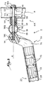
- Figures 2 and 3 illustrate the mounting of a crosspiece stiffening 22 between the lateral tubular elements 18 of the seat 16. According to the embodiment shown, preferably a double joint of the cross member on both the seat 16 and on the two front tubes 8 of the base.
- the crosspiece 22 comprises a main tubular element 28, each end of which receives a corresponding tip 30.
- Each end piece 30 forms a recess, so that a substantial portion of the cross member, namely the element central 28, extends away from axis A.
- the element tubular 28 has, when viewed in plan, a slight bending.
- the cross section of this tubular element 28 is substantially circular towards its ends (figure 5), while it is oval in its middle part (Figure 6). This gives this tubular element 28 has increased resistance to bending.
- Each end piece 30 has a bent shape and has a interlocking section 32, which is intended to enter a end of the tubular element 28, and is extended by a curved portion 34, the end of which opposite the section 32, is drilled with a blind hole 36.
- Each section is provided, as shown in particular in Figure 2, two grooves 35 peripheral devices. The fixing of the element 28 on the end piece 30 is ensured by first fitting element 28 onto the section 32, until this element comes into abutment against the curved portion 34. Then the tubular element 28 is punched, at its faces opposite the grooves 35, as the shows in particular figure 3. This guarantees a subjection reliable of the tubular element 28 with respect to the end piece 30.
- the tubular element is punched 28 in eight points, namely two separate points for each throats 35.
- the blind hole 36 is suitable for cooperating with a screw 38 having a 38A operating head, an intermediate barrel smooth 38B and a threaded end 38C.
- a collar 40 comprising an arch intermediate C-shaped ending with a first end portion 44, generally cylindrical, and a second end portion 46.
- the collar 40 is made of plastic and the arch 42 is dimensioned so that the collar 40 can be fixed by elastic snap around the front tube 8. Such layout guarantees increased ease of assembly.
- the first end 44 of the collar 40 is provided with a through central bore 48, with a diameter close to that of the 38B smooth barrel of screw 38, and has two side faces rounded 50.
- the second end 46 is provided with a through hole 52, arranged in the extension of that 48.
- the face outside of this second end 46, that is to say opposite the first end 44, has a flat 54 forming a seat for the head 38A.
- the inner face 55 of this second end is curved.
- Each front tube 8 is pierced with two orifices 56, intended for the passage of the barrel 38B of the screw 38.
- Two orifices additional 58 arranged in the extension one of the other, are also provided in each tubular element lateral 18 of the seat 16.
- the head 38A of the screw rests on the flat 54.
- the smooth barrel 38B successively crosses the hole 52, holes 56, hole 48 and holes 58.
- the threaded end 38C of the screw 38 is screwed into the hole blind 36 of the nozzle 30, so that the latter is immobilized relative to this screw 38.
- the ends 44, 46 of the collar 40 can rotate around the axis of the screw 38, relative to the front tube 8, by cooperation of shapes with the walls of this front tube, arranged in the vicinity of the orifices 56.
- the end 44 of the collar 40, as well as the curved part 34 of the nozzle 30, can rotate around the axis of the screw 38, relative to the tubular element 18 of the seat 16, by cooperation of shapes with the walls of this element tubular 18 arranged in the vicinity of the orifices 58.
- the end 44 therefore constitutes a connecting piece, forming a spacer, between the frame 18 of the seat 16 and the front tube 8, this which guarantees a reliable articulation between these two elements.
- This arrangement allows on the one hand the articulation of the cross 22 on the tubular element 18 of the seat 16 and on the front tube 8, and on the other hand the articulation of this element tubular 18 on the front tube 8.
- the crosspiece 22 is therefore articulated both on the base and on the seat, this base and this seat being also mutually articulated, all around a common axis A.
- FIGs 7 and 8 show seat 2 in its folded position, in two different arrangements of the cross 22.
- the backrest 24 are successively arranged side by side, the armrest 26, the rear tubular part 6B, the part front tubular 6A, seat 16 and stiffening cross member 22.
- This figure represents the crosspiece 22 in its so-called use position, namely that this cross member protrusion from the seat plane. Since his central element 28 is offset relative to the pivot axis A, this crosspiece is not detrimental to the comfort of a user sitting on the seat.
- Figure 8 shows the crosspiece 22 in a position seat storage. From the position of figure 7, we rotate the crosspiece, for example manually, around of the main axis A of the screw 38. The cross member then rests against the fabric 20 of the seat 16 and therefore does not substantially not protruding from the plane of this seat.
- the width The seat in the retracting position of the cross member ( Figure 8) is significantly less than the width L of the seat in the position of use (figure 7), which is particularly advantageous in terms of seat storage.
- the invention makes it possible to achieve the objectives previously mentioned.
- the crosspiece of the invention provides stability satisfactory to the seat fitted with it, insofar as it extends at the level of the seat articulation axis on the front tubes, and not below this axis, as in the first solution of the prior art.
- this pivoting cross member with respect to the seat can be dimensioned so as to limit the discomfort caused to a user, without inducing significant bulk. In indeed, it is possible to give it a significant bend, which is not detrimental for storage, given that it can be retracted in the vicinity of the seat plane.
- the crosspiece of the invention can easily replace an existing sleeper, for example in the event of a the latter.
- the base in relation to the seat and, on the other hand, the crosspiece with respect to the seat through the same means of articulation guarantees easy assembly of the entire seat and requires only one limited number of liaison bodies.
Landscapes
- Seats For Vehicles (AREA)
- Chairs For Special Purposes, Such As Reclining Chairs (AREA)
Abstract
Description
La présente invention concerne un siège pliant.The present invention relates to a folding seat.
De manière connue, un siège pliant comprend un piétement tubulaire réalisé en deux parties respectivement avant et arrière, comportant chacune deux tubes sensiblement parallèles. Chaque tube de la partie avant, ou tube avant, est relié au tube arrière correspondant par une charnière d'articulation. Une assise est en outre articulée à la fois sur la partie avant de ce piétement, autour d'un axe d'articulation avant, ainsi que sur la partie arrière, autour d'un axe d'articulation arrière. Un dossier est, le cas échéant, également articulé sur ces parties avant et arrière du piétement. Des moyens sont en outre prévus pour maintenir le siège dans sa position pliée ou dépliée, cette dernière pouvant être réglable.In known manner, a folding seat includes a base tubular made in two parts respectively before and rear, each comprising two substantially parallel tubes. Each tube of the front part, or front tube, is connected to the corresponding rear tube by an articulation hinge. A seat is also articulated both on the front part of this base, around an axis of articulation front, as well as on the back, around an axis rear hinge. A file is, if necessary, also articulated on these front and rear parts of the base. Means are also provided for keeping the seat in its folded or unfolded position, the latter being adjustable.
Un tel siège pliant est également équipé d'une traverse de rigidification de la partie avant du piétement. Selon un premier agencement connu, cette traverse s'étend entre les deux tubes avant, au-dessous de l'axe d'articulation de l'assise sur ces tubes.Such a folding seat is also equipped with a crossmember stiffening the front part of the base. According to a first known arrangement, this cross extends between two front tubes, below the articulation axis of the seat on these tubes.
Cette solution connue présente commme inconvénient de ne pas conférer une rigidité suffisante à la partie avant du piétement. En effet, la traverse étant disposée dans une région basse des tubes, elle ne s'oppose pas à leur flexion, lorsqu'un utilisateur est assis sur le siège. De plus, la fixation de cette traverse sur les tubes avant implique le perçage de ceux-ci, ce qui les fragilise.This known solution has the drawback of not not give sufficient rigidity to the front part of the base. Indeed, the cross member being arranged in a lower region of the tubes, it does not oppose their bending, when a user is seated in the seat. In addition, the fixing this crosspiece on the front tubes implies the piercing these, which weakens them.
Il est également connu de disposer cette traverse de rigidification au voisinage de l'assise. A cet effet, la traverse est munie de deux embouts comportant une échancrure en forme de C, dans laquelle est immobilisé un tube d'armature de l'assise. Chacun de ces embouts est articulé sur le tube avant correspondant, par exemple par l'intermédiaire d'une vis traversant à pivotement le tube avant et solidaire de l'embout.It is also known to have this cross stiffening in the vicinity of the seat. To this end, the cross member is provided with two end pieces comprising a notch C-shaped, in which a reinforcing tube is immobilized of the seat. Each of these tips is articulated on the tube corresponding front, for example via a screw pivotally crossing the front tube and secured to the end piece.
Cette seconde solution connue implique elle aussi certains inconvénients. En effet, il est nécessaire de conférer à la traverse une forme cintrée, afin qu'elle s'étende à distance de l'assise de manière à ne pas gêner l'utilisateur, lorsque ce dernier est assis sur le siège. Cependant, si ce cintrage est trop prononcé, la traverse de rigidification fait saillie de manière significative par rapport au plan de l'assise, lorsque le siège se trouve en position pliée, ce qui augmente son encombrement et pose des problèmes de stockage.This second known solution also involves some disadvantages. Indeed, it is necessary to give the crosspiece a curved shape, so that it extends away from the seat so as not to interfere the user, when the latter is seated on the seat. However, if this bending is too pronounced, the crosspiece of stiffening protrudes significantly by relative to the seat plan, when the seat is in folded position, which increases its size and poses storage problems.
Afin de pallier ces divers inconvénients, l'invention se propose de réaliser un siège pliant possédant une traverse qui, tout en conférant une solidité satisfaisante au siège, ne soit pas préjudiciable au confort de l'utilisateur et présente un encombrement réduit, dans la position pliée de ce siège.In order to overcome these various drawbacks, the invention is offers to make a folding seat with a cross which, while imparting satisfactory solidity to the seat, is not detrimental to the comfort of the user and has a small footprint, in the folded position of this seat.
A cet effet, elle a pour objet un siège pliant, du type comprenant un piétement comportant deux parties tubulaires avant et arrière, deux tubes avant de la partie avant étant articulés sur deux tubes arrière de la partie arrière, ledit siège comprenant également une assise articulée d'une part sur les deux tubes avant, autour d'un axe d'articulation avant et d'autre part sur les deux tubes arrière, autour d'un axe d'articulation arrière, ledit siège étant pourvu d'une traverse de rigidification s'étendant entre les tubes avant et libre de pivoter par rapport aux tubes avant, caractérisé en ce que ladite traverse de rigidification est articulée sur l'assise, autour d'un axe contenu sensiblement dans le plan de l'assise.For this purpose, it relates to a folding seat, of the type comprising a base comprising two tubular parts front and rear, two front tubes of the front part being articulated on two rear tubes of the rear part, said seat also comprising a seat articulated on the one hand on the two front tubes, around a front articulation axis and on the other hand on the two rear tubes, around an axis rear articulation, said seat being provided with a stiffening crosspiece extending between the front tubes and free to pivot relative to the front tubes, characterized in that said stiffening cross member is articulated on the seat, around an axis contained substantially in the plane of the seat.
Selon d'autres caractéristiques de l'invention :
- une portion substantielle de la traverse est déportée par rapport à l'axe d'articulation de cette traverse sur l'assise ;
- la traverse est articulée sur l'assise, autour de l'axe d'articulation avant ;
- le siège est pourvu de moyens d'articulation communs d'une part de l'assise sur les tubes avant et d'autre part de la traverse sur l'assise ;
- les moyens d'articulation communs comprennent deux articulations comportant chacune une vis traversant, à pivotement libre et à assujettissement axial, le tube avant, une armature de l'assise et une pièce de liaison, intercalée entre le tube avant et l'armature et libre de pivoter par rapport à ce tube avant et cette armature, chaque vis étant solidarisée à la traverse ;
- la pièce de liaison possède deux faces latérales bombées coopérant avec des parois du tube avant et de l'armature, disposées au voisinage d'orifices de passage de la vis, ménagés dans ce tube avant et cette armature ;
- la pièce de liaison appartient à un collier entourant au moins en partie le tube avant et comportant une portion formant siège pour une tête de la vis ;
- le collier est fixé au tube avant par encliquetage élastique ;
- la traverse comprend un élément tubulaire central et deux embouts fixés aux extrémités dudit élément central et coopérant avec les moyens d'articulation ;
- l'élément central a, au moins dans sa partie médiane, une section transversale ovale.
- a substantial portion of the cross member is offset relative to the axis of articulation of this cross member on the seat;
- the cross member is articulated on the seat, around the front articulation axis;
- the seat is provided with common articulation means on the one hand of the seat on the front tubes and on the other hand of the cross member on the seat;
- the common articulation means comprise two articulations each comprising a through screw, freely pivoting and axially secured, the front tube, a frame of the seat and a connecting piece, interposed between the front tube and the frame and free to pivot relative to this front tube and this frame, each screw being secured to the crosspiece;
- the connecting piece has two curved side faces cooperating with walls of the front tube and of the frame, arranged in the vicinity of orifices for the passage of the screw, formed in this front tube and this frame;
- the connecting piece belongs to a collar at least partially surrounding the front tube and comprising a portion forming a seat for a head of the screw;
- the collar is fixed to the front tube by elastic snap-fastening;
- the cross member comprises a central tubular element and two end pieces fixed to the ends of said central element and cooperating with the articulation means;
- the central element has, at least in its middle part, an oval cross section.
L'invention va être décrite ci-dessous, en référence aux dessins annexés, donnés uniquement à titre d'exemples non limitatifs et dans lesquels :
- la figure 1 est une vue en perspective d'un siège pliant conforme à l'invention ;
- la figure 2 est une vue en perspective éclatée d'un embout de la traverse de rigidification du siège de la figure 1, ainsi que des moyens permettant l'articulation de cet embout par rapport au piétement et à l'assise de ce siège ;
- la figure 3 est une vue en coupe frontale illustrant les différents éléments de la figure 2, une fois montés sur le piétement et l'assise du siège ;
- la figure 4 est une vue en plan de l'ensemble de la traverse équipant le siège des figures précédentes ;
- les figures 5 et 6 sont des coupes transversales selon les lignes V-V et VI-VI à la figure 4 ; et
- les figures 7 et 8 sont des vues partielles de côté illustrant le siège des figures précédentes dans sa position pliée, la traverse se trouvant dans deux configurations différentes.
- Figure 1 is a perspective view of a folding seat according to the invention;
- Figure 2 is an exploded perspective view of a tip of the cross member for stiffening the seat of Figure 1, as well as means for the articulation of this tip relative to the base and the seat of this seat;
- Figure 3 is a front sectional view illustrating the various elements of Figure 2, once mounted on the base and the seat;
- Figure 4 is a plan view of the entire cross member fitted to the seat of the preceding figures;
- Figures 5 and 6 are cross sections along lines VV and VI-VI in Figure 4; and
- Figures 7 and 8 are partial side views illustrating the seat of the preceding figures in its folded position, the crosspiece being in two different configurations.
La figure 1 représente un siège conforme à l'invention,
désigné dans son ensemble par la référence 2. Ce siège repose
sur le sol par un piétement 4, qui comprend des parties
tubulaires en forme de U respectivement avant 6A et arrière
6B. La partie avant 6A comporte deux tubes avant 8 reliés par
une traverse avant 10, tandis que la partie arrière comporte
deux tubes arrière 12 reliés par une traverse arrière 14. Les
parties tubulaires 6A, 6B sont mutuellement articulées au
moyen de charnières non représentées, de type connu.FIG. 1 represents a seat according to the invention,
designated as a whole by the
Une assise 16 est articulée sur le piétement 4, à la fois
sur les tubes avant 8 autour d'un axe A et sur les tubes
arrière 12 autour d'un axe A' parallèle à l'axe A. A et A'
sont dénommés axes d'articulation respectivement avant et
arrière.A
L'assise 16 comprend une armature tubulaire périphérique
en forme de U, comprenant deux éléments tubulaires latéraux
18 reliés par un élément tubulaire arrière 19. Une toile 20,
réalisée par exemple en tissu, est assujettie à l'armature de
l'assise, de façon connue.
Le siège 2 est également équipé, de façon connue, d'un
dossier 24 articulé sur la partie arrière 6B du piétement 4
et sur l'assise 16. Des accoudoirs 26 s'étendent à partir du
dossier 24 jusqu'aux charnières d'articulation entre les tubes
avant 8 et arrière 12. Ces accoudoirs sont munis de moyens
connus 27 permettant de conférer une inclinaison variable au
dossier 24.The
Les figures 2 et 3 illustrent le montage d'une traverse
de rigidification 22 entre les éléments tubulaires latéraux
18 de l'assise 16. Selon le mode de réalisation représenté,
on utilise de préférence une articulation double de la
traverse à la fois sur l'assise 16 et sur les deux tubes avant
8 du piétement.Figures 2 and 3 illustrate the mounting of a crosspiece
stiffening 22 between the lateral
La traverse 22 comprend un élément tubulaire principal
28, dont chaque extrémité reçoit un embout correspondant 30.
Chaque embout 30 forme un décrochement, de sorte qu'une
portion substantielle de la traverse, à savoir l'élément
central 28, s'étend à distance de l'axe A.The
Comme le montre en particulier la figure 4, l'élément
tubulaire 28 présente, vu en plan, un léger cintrage. La
section transversale de cet élément tubulaire 28 est sensiblement
circulaire vers ses extrémités (figure 5), alors qu'elle
est ovale dans sa partie médiane (figure 6). Ceci confère à
cet élément tubulaire 28 une résistance accrue à la flexion.As shown in particular in Figure 4, the element
tubular 28 has, when viewed in plan, a slight bending. The
cross section of this
Chaque embout 30 possède une forme coudée et comporte un
tronçon d'emboítement 32, qui est destiné à pénétrer dans une
extrémité de l'élément tubulaire 28, et se prolonge par une
partie recourbée 34, dont l'extrémité opposée au tronçon 32,
est percée d'un trou borgne 36. Chaque tronçon est muni, comme
le montre en particulier la figure 2, de deux gorges 35
périphériques. La fixation de l'élément 28 sur l'embout 30 est
assurée en emmanchant tout d'abord l'élément 28 sur le tronçon
32, jusqu'à ce que cet élément vienne en butée contre la
partie recourbée 34. Puis on poinçonne l'élément tubulaire 28,
au niveau de ses faces en regard des gorges 35, comme le
montre en particulier la figure 3. Ceci garantit un assujettissement
fiable de l'élément tubulaire 28 par rapport à
l'embout 30. De préférence, on poinçonne l'élément tubulaire
28 en huit points, à savoir deux points distincts pour chacune
des gorges 35.Each
Le trou borgne 36 est propre à coopérer avec une vis 38
possédant une tête de manoeuvre 38A, un fût intermédiaire
lisse 38B et une extrémité filetée 38C.The
L'articulation de la traverse 22 est également assurée
par l'intermédiaire d'un collier 40 comportant une arche
intermédiaire 42 en forme de C terminée par une première
portion d'extrémité 44, globalement cylindrique, et une
seconde portion d'extrémité 46.The articulation of the
Le collier 40 est réalisé en matière plastique et l'arche
42 est dimensionnée de manière que le collier 40 puisse être
fixé par encliquetage élastique autour du tube avant 8. Un tel
agencement garantit une facilité de montage accrue.The
La première extrémité 44 du collier 40 est pourvue d'un
perçage central traversant 48, de diamètre voisin de celui du
fût lisse 38B de la vis 38, et elle possède deux faces latérales
bombées 50.The
La deuxième extrémité 46 est pourvue d'un perçage traversant
52, disposé dans le prolongement de celui 48. La face
extérieure de cette deuxième extrémité 46, c'est-à-dire
opposée à la première extrémité 44, comporte un méplat 54
formant un siège pour la tête 38A. La face intérieure 55 de
cette seconde extrémité est bombée.The
Chaque tube avant 8 est percé de deux orifices 56,
destinés au passage du fût 38B de la vis 38. Deux orifices
supplémentaires 58, disposés dans le prolongement l'un de
l'autre, sont également ménagés dans chaque élément tubulaire
latéral 18 de l'assise 16.Each
Une fois le siège assemblé, la tête 38A de la vis repose
sur le méplat 54. Le fût lisse 38B traverse successivement le
perçage 52, les orifices 56, le perçage 48 et les orifices 58.
L'extrémité filetée 38C de la vis 38 est vissée dans le trou
borgne 36 de l'embout 30, de sorte que ce dernier est immobilisé
par rapport à cette vis 38.Once the seat is assembled, the
Les extrémités 44, 46 du collier 40 peuvent tourner
autour de l'axe de la vis 38, par rapport au tube avant 8, par
coopération de formes avec les parois de ce tube avant,
disposées au voisinage des orifices 56.The ends 44, 46 of the
L'extrémité 44 du collier 40, ainsi que la partie recourbée
34 de l'embout 30, peuvent tourner autour de l'axe de la
vis 38, par rapport à l'élément tubulaire 18 de l'assise 16,
par coopération de formes avec les parois de cet élément
tubulaire 18 disposées au voisinage des orifices 58. L'extrémité
44 constitue donc une pièce de liaison, formant entretoise,
entre l'armature 18 de l'assise 16 et le tube avant 8, ce
qui garantit une articulation fiable entre ces deux éléments.The
Cet agencement permet d'une part l'articulation de la
traverse 22 sur l'élément tubulaire 18 de l'assise 16 et sur
le tube avant 8, et d'autre part l'articulation de cet élément
tubulaire 18 sur le tube avant 8. La traverse 22 est donc
articulée à la fois sur le piétement et sur l'assise, ce
piétement et cette assise étant en outre mutuellement articulés,
le tout autour d'un axe commun A.This arrangement allows on the one hand the articulation of the
Les figures 7 et 8 représentent le siège 2 dans sa
position repliée, dans deux agencements différents de la
traverse 22. Figures 7 and 8
Comme le montre la figure 7, dans la position repliée du
siège, sont successivement disposés côte à côte le dossier 24,
l'accoudoir 26, la partie tubulaire arrière 6B, la partie
tubulaire avant 6A, l'assise 16 et la traverse de rigidification
22. Cette figure représente la traverse 22 dans sa
position dite d'utilisation, à savoir que cette traverse fait
saillie par rapport au plan de l'assise. Etant donné que son
élément central 28 est déporté par rapport à l'axe de pivotement
A, cette traverse n'est pas préjudiciable au confort d'un
utilisateur assis sur le siège.As shown in Figure 7, in the folded position of the
seat, the
La figure 8 représente la traverse 22 dans une position
de stockage du siège. A partir de la position de la figure 7,
on fait pivoter la traverse, par exemple manuellement, autour
de l'axe principal A de la vis 38. La traverse repose alors
contre la toile 20 de l'assise 16 et ne fait donc sensiblement
pas saillie par rapport au plan de cette assise. La largeur
L' du siège dans la position d'escamotage de la traverse
(figure 8) est nettement inférieure à la largeur L du siège
dans la position d'utilisation (figure 7), ce qui est
particulièrement avantageux en termes de stockage du siège.Figure 8 shows the
Lorsqu'on déplie le siège à partir de sa position illustrée
sur cette figure 8, on fait pivoter la traverse 22 autour
de l'axe principal de la vis 38, de manière à l'amener dans
sa position d'utilisation, représentée à la figure précédente.When unfolding the seat from its illustrated position
in this figure 8, we rotate the
L'invention permet de réaliser les objectifs précédemment mentionnés. La traverse de l'invention confère une stabilité satisfaisante au siège qui en est équipé, dans la mesure où elle s'étend au niveau de l'axe d'articulation de l'assise sur les tubes avant, et non pas au-dessous de cet axe, comme dans la première solution de l'art antérieur.The invention makes it possible to achieve the objectives previously mentioned. The crosspiece of the invention provides stability satisfactory to the seat fitted with it, insofar as it extends at the level of the seat articulation axis on the front tubes, and not below this axis, as in the first solution of the prior art.
De plus, cette traverse pivotante par rapport à l'assise peut être dimensionnée de manière à limiter la gêne apportée à un utilisateur, sans induire un encombrement important. En effet, il est possible de lui conférer un cintrage important, qui n'est pas préjudiciable pour le stockage, étant donné qu'elle peut être escamotée au voisinage du plan de l'assise.In addition, this pivoting cross member with respect to the seat can be dimensioned so as to limit the discomfort caused to a user, without inducing significant bulk. In indeed, it is possible to give it a significant bend, which is not detrimental for storage, given that it can be retracted in the vicinity of the seat plane.
De plus, la traverse de l'invention peut aisément remplacer une traverse existante, par exemple en cas de rupture de cette dernière.In addition, the crosspiece of the invention can easily replace an existing sleeper, for example in the event of a the latter.
Articuler, d'une part, le piétement par rapport à l'assise et, d'autre part, la traverse par rapport à l'assise par l'intermédiaire de mêmes moyens d'articulation garantit un montage facile de l'ensemble du siège et ne nécessite qu'un nombre restreint d'organes de liaison.To articulate, on the one hand, the base in relation to the seat and, on the other hand, the crosspiece with respect to the seat through the same means of articulation guarantees easy assembly of the entire seat and requires only one limited number of liaison bodies.
L'existence d'un méplat formant siège pour la tête de vis permet d'empêcher le contact direct entre le tube avant et cette tête de vis qui pivote par rapport à ce dernier lors de chaque pliage ou dépliage du siège. Une telle disposition garantit une solidarisation fiable de la vis par rapport à l'embout de la traverse dans laquelle elle est fixée.The existence of a flat forming a seat for the screw head prevents direct contact between the front tube and this screw head which pivots relative to the latter during each folding or unfolding of the seat. Such a provision guarantees reliable fastening of the screw in relation to the tip of the crosspiece in which it is fixed.
Claims (10)
Applications Claiming Priority (2)
| Application Number | Priority Date | Filing Date | Title |
|---|---|---|---|
| FR9814585 | 1998-11-17 | ||
| FR9814585A FR2785779B1 (en) | 1998-11-17 | 1998-11-17 | FOLDING SEAT |
Publications (1)
| Publication Number | Publication Date |
|---|---|
| EP1002485A1 true EP1002485A1 (en) | 2000-05-24 |
Family
ID=9532956
Family Applications (1)
| Application Number | Title | Priority Date | Filing Date |
|---|---|---|---|
| EP99420227A Withdrawn EP1002485A1 (en) | 1998-11-17 | 1999-11-15 | Folding seat |
Country Status (2)
| Country | Link |
|---|---|
| EP (1) | EP1002485A1 (en) |
| FR (1) | FR2785779B1 (en) |
Cited By (1)
| Publication number | Priority date | Publication date | Assignee | Title |
|---|---|---|---|---|
| US11241097B2 (en) * | 2019-06-04 | 2022-02-08 | Yeti Coolers, Llc | Portable chair |
Citations (2)
| Publication number | Priority date | Publication date | Assignee | Title |
|---|---|---|---|---|
| GB261200A (en) * | 1925-12-05 | 1926-11-18 | John James Henry Schneider | Improvements in or relating to chairs |
| US4234226A (en) * | 1978-10-02 | 1980-11-18 | Scott Paper Company | Adjustable and collapsible seating piece |
-
1998
- 1998-11-17 FR FR9814585A patent/FR2785779B1/en not_active Expired - Fee Related
-
1999
- 1999-11-15 EP EP99420227A patent/EP1002485A1/en not_active Withdrawn
Patent Citations (2)
| Publication number | Priority date | Publication date | Assignee | Title |
|---|---|---|---|---|
| GB261200A (en) * | 1925-12-05 | 1926-11-18 | John James Henry Schneider | Improvements in or relating to chairs |
| US4234226A (en) * | 1978-10-02 | 1980-11-18 | Scott Paper Company | Adjustable and collapsible seating piece |
Cited By (1)
| Publication number | Priority date | Publication date | Assignee | Title |
|---|---|---|---|---|
| US11241097B2 (en) * | 2019-06-04 | 2022-02-08 | Yeti Coolers, Llc | Portable chair |
Also Published As
| Publication number | Publication date |
|---|---|
| FR2785779B1 (en) | 2001-02-09 |
| FR2785779A1 (en) | 2000-05-19 |
Similar Documents
| Publication | Publication Date | Title |
|---|---|---|
| FR2775891A1 (en) | Partial posterior intervertebral disc prosthesis | |
| EP0689784B1 (en) | Relax-chair | |
| WO2005121873A1 (en) | Compact elastic hinge element for a spectacle frame | |
| EP0521762B1 (en) | Column destined for a support which is equipped with a gas spring | |
| FR2942889A1 (en) | FRAME FOR TELESCOPIC HINGED GLASSES AND HINGE FOR THE FRAME | |
| FR2853949A1 (en) | Motor vehicle exhaust pipe suspension hook, has strut with end comprising bracket fixed with nozzle, where nozzle cooperates with bracket by intermediate of contact of plane type with distance. | |
| EP0259201B1 (en) | Chair structure, particularly for a chair with an adjustable back | |
| FR2658053A1 (en) | LIQUID APPLICATOR, FOR EXAMPLE LIQUID FOR HAIR DYEING. | |
| EP1002485A1 (en) | Folding seat | |
| FR2681517A1 (en) | Support for a toothbrush with removable fastening | |
| FR2713064A1 (en) | Seat whose articulated backrest serves as a protective cover for the seat when folded. | |
| EP0401105A1 (en) | Pen or pen-like instrument with improved clip | |
| FR2491312A1 (en) | Seat with removable armrest - has hinge mechanism with axle joining seat and back rest between which is flexible strip forming arm rest | |
| EP0045679A1 (en) | Transformable seat | |
| EP0468899A1 (en) | System to detachably connect a part to a fixed member, said part being in particular a wheel-cover | |
| FR2555877A3 (en) | ADJUSTABLE ARMCHAIR | |
| FR2757646A1 (en) | ELASTIC HINGE OF EYEWEAR | |
| FR2477729A1 (en) | Improved metal legs for spectacle frame - are hollow with flexible cord inside and deformable hook ends to go around ear | |
| FR2714638A1 (en) | Support and direction device for vehicle rear view mirror | |
| EP0937427A1 (en) | Frame for a folding chair and folding chair with said frame | |
| FR2720996A1 (en) | Bicycle saddle which pivots with rider's movements | |
| FR2787689A1 (en) | Armrest for folding seat has upper and lower plastic parts attached with sockets and pegs | |
| BE1017610A3 (en) | FOOTREST FOR SEATS. | |
| FR2550927A1 (en) | Articulation for folding chair and folding article of similar structure | |
| FR2517945A1 (en) | Metal frame for chair - comprises seat cover support and frame with legs backrest and crosspieces |
Legal Events
| Date | Code | Title | Description |
|---|---|---|---|
| PUAI | Public reference made under article 153(3) epc to a published international application that has entered the european phase |
Free format text: ORIGINAL CODE: 0009012 |
|
| AK | Designated contracting states |
Kind code of ref document: A1 Designated state(s): DE DK ES FR GB NL |
|
| AX | Request for extension of the european patent |
Free format text: AL;LT;LV;MK;RO;SI |
|
| 17P | Request for examination filed |
Effective date: 20001124 |
|
| AKX | Designation fees paid |
Free format text: DE DK ES FR GB NL |
|
| STAA | Information on the status of an ep patent application or granted ep patent |
Free format text: STATUS: THE APPLICATION HAS BEEN WITHDRAWN |
|
| 17Q | First examination report despatched |
Effective date: 20021029 |
|
| 18W | Application withdrawn |
Withdrawal date: 20021031 |