EP1001579A1 - Procédé et dispositif pour déterminer les propriétés d'un canal de transmission - Google Patents
Procédé et dispositif pour déterminer les propriétés d'un canal de transmission Download PDFInfo
- Publication number
- EP1001579A1 EP1001579A1 EP98121134A EP98121134A EP1001579A1 EP 1001579 A1 EP1001579 A1 EP 1001579A1 EP 98121134 A EP98121134 A EP 98121134A EP 98121134 A EP98121134 A EP 98121134A EP 1001579 A1 EP1001579 A1 EP 1001579A1
- Authority
- EP
- European Patent Office
- Prior art keywords
- digital
- subscriber
- frame
- symbols
- telephone network
- Prior art date
- Legal status (The legal status is an assumption and is not a legal conclusion. Google has not performed a legal analysis and makes no representation as to the accuracy of the status listed.)
- Withdrawn
Links
Images
Classifications
-
- H—ELECTRICITY
- H04—ELECTRIC COMMUNICATION TECHNIQUE
- H04L—TRANSMISSION OF DIGITAL INFORMATION, e.g. TELEGRAPHIC COMMUNICATION
- H04L43/00—Arrangements for monitoring or testing data switching networks
-
- H—ELECTRICITY
- H04—ELECTRIC COMMUNICATION TECHNIQUE
- H04L—TRANSMISSION OF DIGITAL INFORMATION, e.g. TELEGRAPHIC COMMUNICATION
- H04L43/00—Arrangements for monitoring or testing data switching networks
- H04L43/10—Active monitoring, e.g. heartbeat, ping or trace-route
-
- H—ELECTRICITY
- H04—ELECTRIC COMMUNICATION TECHNIQUE
- H04L—TRANSMISSION OF DIGITAL INFORMATION, e.g. TELEGRAPHIC COMMUNICATION
- H04L43/00—Arrangements for monitoring or testing data switching networks
- H04L43/16—Threshold monitoring
Definitions
- the invention relates to a method of determining properties of a signal transmission channel between a first subscriber end point and a second subscriber end point of a telephone network having a plurality of subscribers, wherein a first subscriber terminal is connected to said first subscriber end point and a second subscriber terminal is connected to said second subscriber end point, wherein said telephone network upon request of a subscriber establishes a signal transmission channel between said first subscriber and said second subscriber, wherein said first subscriber end point is connected to the telephone network by a digital channel portion.
- the invention further relates to a subscriber terminal in a telephone network having a plurality of subscribers, wherein said telephone network upon request of a subscriber establishes a signal transmission channel between selected subscribers, said subscriber terminal being connected to a subscriber end point of said telephone network.
- the analogue signals originating from a first subscriber modem are converted at the subscriber's central office to digital representations which are carried through the digital telephone network.
- the digital signals are converted back into analogue signals to be driven into a second subscriber's subscriber line.
- the second subscriber's modem interprets the analogue signals on the analogue subscriber line by demodulating the QAM signals produced by the first subscriber's modem. The same way of data communication is carried out in the reverse direction.
- the proposal is based on the idea that the transmission rate in a heterogeneous communication channel from the digital subscriber to the analogue subscriber may be raised by using a PCM coding technique instead of the former QAM modulation techniques.
- the PCM coding technique uses a plurality of signal levels for encoding data symbols (each data symbol comprising multiple bits). These signal levels are again recognised by the receiving modem which is then able to decode the data symbol encoded into the signal levels.
- ITU has promulgated a new recommendation V.90 in September 1998.
- the new recommendation also relies on a PCM coding technique for the transmission of data from the digital subscriber to the analogue subscriber.
- Draft recommendation V.90 in terms of its PCM coding scheme depends on ITU-T recommendation G.711 describing Pulse Code Modulation (PCM) of Voice Frequencies which is generally applied in telephone networks throughout the world when converting analogue signal amplitude values into numeric representations thereof, and vice versa.
- G.711 recommends two PCM coding schemes generally known as ⁇ -law, which is applied in North American telephone networks, and A-law, which is applied in most other telephone networks.
- Both coding schemes have in common that they have a logarithmic coding characteristic, i.e. the lower the signal amplitude value to be encoded, the more fine-grain the available PCM codes.
- logarithmic coding characteristic has been found to be particularly advantageous for encoding analogue voice signals at minimum distortion.
- Recommendation G.711 makes available 256 PCM codes (or U-codes as called in V.90) which are grouped into eight positive and eight negative segments (or U-chords as called in V.90). Each PCM code is encoded using eight bits. Due to power restrictions on the analogue telephone line and due to line impairments, the analogue modem (according to the terminology used in the draft to V.90) receiving analogue amplitude values is unable to discriminate between all 256 available PCM codes. Therefore, a reduced set of PCM codes is determined for encoding data symbols during set-up of a data communication channel under real world conditions. This accordingly lowers the data transmission rate down from the maximum theoretical possible value of 64 kbit/s such that it is not above 56 kbit/s.
- ITU-T Recommendation V.90 assumes an environment where one subscriber terminal of a connection is connected to the telephone network through a digital line and the other subscriber terminal of the connection is connected to the telephone network through an analogue line. However, in many instances, both subscriber terminals of a connection are connected to the telephone network through a digital connection. This situation would allow to establish an all-digital channel between the two subscriber terminals at a data rate of 64 kbit/s, which is the standard data rate in telephone networks.
- US 5,151,398 discloses modem line probing signal techniques. These probing techniques relate to former analogue line modems defined for example in ITU-T V.34.
- a first embodiment of the invention pertains to a method of determining properties of a signal transmission channel between a first subscriber end point and a second subscriber end point of a telephone network having a plurality of subscribers.
- a first subscriber terminal is connected to said first subscriber end point and a second subscriber terminal is connected to said second subscriber end point.
- Said telephone network upon request of a subscriber establishes a signal transmission channel between said first subscriber and said second subscriber.
- Said first subscriber end point is connected to the telephone network by a digital channel portion.
- said first subscriber terminal sends to said second subscriber terminal a digital probing signal comprising a sequence of frames, each frame comprising a sequence of digital symbols, each symbol having a plurality of bits.
- the digital values of all symbols over all frames are equal except for one bit position of each symbol, the value of which changes with every other frame.
- Said second subscriber terminal then receives a signal which is the result of said digital probing signal having been transmitted through said signal transmission channel.
- Said second subscriber terminal evaluates said received signal by comparing said received signal with said digital probing signal. Eventually, said second subscriber terminal transmitting a response signal to said first subscriber terminal, said response signal carrying information about the comparison result.
- a second embodiment of the invention also concerns a method of determining properties of a signal transmission channel between a first subscriber end point and a second subscriber end point of a telephone network having a plurality of subscribers.
- This method alternatively provides that said first subscriber terminal sends to said second subscriber terminal a digital probing signal comprising a sequence of frames, each frame comprising a sequence of digital symbols, each symbol having a plurality of bits, wherein the digital values of all symbols are equal except for at least one pulse symbol of each frame having a significantly different digital value compared to the remaining equal values.
- the line probing schemes proposed by the invention allow both to find out whether an all-digital transmission channel is present between said first subscriber end point and said second subscriber end point and further to find out the transmission properties of the all-digital transmission channel. Since the transmission channels of most telephone networks are primarily intended for voice signal transmission, some networks impose digital signal impairments upon the digital signals carried through the network's channels. Such digital impairments include digital padding (digital signal attenuation), robbed bit signalling, ADPCM (Advanced Differential Pulse Code Modulation) coding and voice compression algorithms. The latter impairments allow to reduce the bit rate of 64 kbit/s generally reserved for a full channel to a lower rate without much sacrifice to the quality of voice signal transmission, thus making available bandwidth for other purposes.
- digital padding digital signal attenuation
- ADPCM Advanced Differential Pulse Code Modulation
- the methods of the invention are capable of discriminating whether an all-digital channel is present and whether or not the all-digital channel has digital impairments.
- the methods of the invention are even capable of discriminating what kind of digital impairment is present in an all-digital transmission channel. Knowing the kind of digital impairment allows the conclusion as to whether a transmission scheme between said first subscriber terminal and said second subscriber terminal is possible according to V.90 or another lower rate scheme such as V.34.
- said one bit position is the most significant bit position. This way, the absolute digital value difference from one frame to another is as large as possible. It is even further preferred that said one bit position is the position of the sign bit. This way of line probing ensures that no direct current is produced in an analogue channel portion which may be present in the transmission channel to be probed.
- one bit position of said at least one pulse symbol changes value with every other frame.
- frames can be identified as such more easily by the second subscriber terminal.
- said one bit position is the position of the sign bit. This ensures that no direct current is produced in an analogue channel portion which may be present in the transmission channel to be probed.
- the number of equal symbols per frame is significantly higher than the number of pulse symbols. This allows said second subscriber terminal to clearly identify a pulse symbol as such. Preferably, there is one pulse symbol per frame.
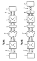
- Fig. 1a illustrates an all-digital signal transmission path between a first subscriber terminal 1 and a second subscriber terminal 8.
- the first subscriber terminal 1 (a digital modem) is connected through a digital line portion 2 to a local digital switch 3.
- the local switch 3 is connected to a digital transmission network 4 which forwards digital signals between subscribers of the transmission network.
- the second subscriber terminal 8 is connected through a digital line portion 7 to a local digital switch 6.
- the local switch 6 is connected to the transmission network 4 through a digital impairment device 5.
- Fig. 1a shows an exemplary position of the digital impairment device within the transmission pat.
- the digital impairment device may as well be part of any of the digital switches 3 and 6 or may be part of the transmission network 4 or of the transmission path 7.
- Digital impairments include digital padding (digital signal attenuation), robbed bit signalling (RBS), and ADPCM (Advanced Differential Pulse Code Modulation) coding or other voice compression algorithms which may be imposed upon the signals passing through the impairment device 5.
- Digital impairment devices are present in many existing transmission networks and have to be accounted for when trying to establish a connection between subscriber terminals of the network at the highest bit rate possible.
- Fig. 1b shows a similar configuration as Fig. 1a except that the second subscriber terminal 8' is connected to the transmission network through an analogue line portion 7'.
- the transmission path of Fig. 1a consequently includes a hybrid device 9' which is connected to the analogue line portion 7' and performs a four-wire to two-wire conversion. Additionally, the hybrid device 9' performs, on the four-wire side, a digital-to-analogue and an analogue-to-digital signal conversion so as to be connected to a digital switch 6'.
- the remaining structure of Fig. 1b corresponds to the one shown in Fig. 1a. Thus, the description of the remaining elements may be referred to by similar reference numerals.
- Both Fig. 1a and Fig. 1b illustrate exemplary structures of transmission paths that may be encountered when trying to establish a connection between two subscribers of a transmission network wherein at least of the two subscribers is connected to the network through a digital line portion such as ISDN.
- a digital line portion such as ISDN.
- Known transmission schemes are ITU-T V.34 using quadrature amplitude modulation on analogue transmission paths and ITU-T V.90 using pulse amplitude modulation on transmission paths having both analogue and digital line portions. Further, pulse amplitude modulation according to ITU-T V.90 can also be used as a transmission scheme on all-digital transmission paths.
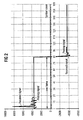
- Fig. 2 is a diagram of a probing signal of the first embodiment of the invention.
- the probing signal is transmitted by the first subscriber terminal 1 and of a signal received by the second subscriber terminal 8 in the presence of a digital impairment device 5 introducing ADPCM to the signal transmission path between the first subscriber and the second subscriber.
- Terminal 1 sends 80 digital symbols of equal value in a first frame and then sends 80 digital symbols of the same absolute value, however, being negative in sign.
- the probing signal consists of a plurality of frame pairs as illustrated in Fig. 2 subsequently transmitted by the first terminal 1.
- the received signal does not precisely follow the large signal swings from one frame to another.
- the second terminal 8 may interpret this as an all-digital transmission path which is not transparent due to ADPCM.
- Such a connection is not capable of carrying an ITU-T V.90 transmission scheme.
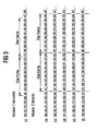
- Fig. 3 shows a digital symbol sequence of a probing signal (sequence a) transmitted by the first subscriber terminal 1 (Modem 1) according to a second embodiment of the invention and various cases of received signals (sequences b through g).
- Fig. 3 shows a frame structure of 9 symbols per frame. It is preferred to use a much higher symbol count per frame, preferably 80 symbols per frame.
- Each digital symbol shown in Fig 3 is a hexadecimal representation of an 8 bit digital value corresponding to the U-code representation as defined in ITU-T V.90.
- the first symbol of the first probing frame in sequence (a) is 4Ch (the character h indicating hexadecimal representation in this text).
- the first symbol of the second probing frame in sequence (a) is CCh, which is equal to 4Ch except for one bit position. According to ITU-T G.711, this bit position is the sign bit of a signal represented by the digital symbol. All remaining symbols are at value 00h. Thus, the first symbol forms a signal pulse.
- Sequence (b) of Fig. 3 shows the signal received by subscriber terminal 8 (Modem 2) in the case of an all-digital, fully transparent connection.
- Modem 2 subscriber terminal 8
- Sequence (b) through (g) show received signals in the presence of digital impairments.
- Sequence (c) assumes an impairment of digital padding, i.e. the digital signal is attenuated.
- the pulse symbol in the original probing sequence (a) is lower in its absolute value.
- Sequence (d) shows a received signal in the presence of digital impairment in the form of robbed bit signalling (RBS).
- RBS is applied to a least significant bit of every sixth symbol.
- the received signal differs from the original probing sequence every sixth symbol.
- Sequence (e) shows a received signal in the presence of both digital padding and RBS.
- sequence (f) shows a received signal under the influence of ADPCM or another voice compression algorithm.
- the ADPCM coder cannot follow the high pulse symbol 4Ch of the probing sequence interspersed in the zero symbols 00h.
- the pulse symbol of modem 1 is received with a much wider pulse width and less high amplitude in modem 2. This is a clear indication of ADPCM.
- the invention generally also relates to a modem connected via a digital interface to a switched public telephone network.
- the modem communicates with a second modem also connected via a digital interface to the same switched public telephone network.
- the public telephone network may incorporate voice compression devices (ADPCM G.726, G.723 etc.), digital pads (digital attenuators), robbed bit signalling and echo cancelling devices.
- the probing sequence of the invention uses large amplitude changes in a symbol sequence (each symbol having a duration of 125 ⁇ s).
- the meaning of amplitude relates to the definition of ITU-T recommendation G.711.
- the signal may return to the previous value or continue with the new amplitude value for a number of symbols.
- the number of symbols is selected to be larger than any expected impulse response of a digital impairment of the channel.
- the amplitude value change must be large enough to produce a sufficient result in the presence of digital pads with or without the presence of RBS.
- the receiving modem will evaluate the received symbols and search for amplitude changes. If these changes occur only for one symbol per frame and the following symbols either return to the previous value or remain at the new value, the connection is detected as capable to carry a V.90 transmission scheme. If, however, the symbols after an amplitude change do not remain at the new value or do not return to the value before the change (in other words there is an impulse response over time), it is determined, that a connection according to ITU-T V.90 is not possible.
- Typical impairments having an impulse response are voice compression algorithms and ADPCM, which may be regarded a compression algorithm, too. Whereas ADPCM has a characteristic impulse response to an change in amplitude, it depends on the design of a voice compression algorithm how large amplitude swings are processed and coded into the output signal of the voice compression coder.
- Robbed bit signalling changes the least significant bit (LSB) in some symbols but leaves the remaining seven bits unchanged. A single amplitude change will therefore only be affected in the LSB, the remaining seven bits, however, will not change.
- Digital pads use conversion functions which defines an output value to a PCM input value thus providing digital attenuation. This function will only change the absolute value of the amplitude but it will not affect the behaviour of the signal over time.
- modem 1 will generate a pattern as described in conjunction with Fig. 3 and sends the pattern through the transmission channel to modem 2.
- Modem 2 will receive a pattern which differs from the transmit pattern due to network impairments.
- Modem 2 will evaluate the pattern in the following way: It will first logical AND the pattern with FEh in order to ignore changes in the LSB. Next it will compare this new value with the previous one. If they are identical, a counter is incremented. If they are different, then the current count value is compared to the expected value and if they differ, an error counter is incremented. Then the counter is reset to zero and the new value is transferred to the old value register. When all symbols have been evaluated, the value of the error counter is compared to a fixed threshold value. If the error counter value is below the threshold, then it is determined that the connection is not capable of carrying an ITU-T V.90 type transmission scheme.
- the appended program codes show how line probing signals according to the invention may be produced.
- the programs are based on a pseudo code.
- the program of appendix A corresponds to the embodiment of Fig. 2, and the program of appendix B corresponds to the embodiment of Fig. 3. By no means are these program a limitation of the invention.
Landscapes
- Engineering & Computer Science (AREA)
- Computer Networks & Wireless Communication (AREA)
- Signal Processing (AREA)
- Telephonic Communication Services (AREA)
- Analogue/Digital Conversion (AREA)
- Use Of Switch Circuits For Exchanges And Methods Of Control Of Multiplex Exchanges (AREA)
- Monitoring And Testing Of Exchanges (AREA)
- Interface Circuits In Exchanges (AREA)
Priority Applications (6)
| Application Number | Priority Date | Filing Date | Title |
|---|---|---|---|
| EP98121134A EP1001579A1 (fr) | 1998-11-10 | 1998-11-10 | Procédé et dispositif pour déterminer les propriétés d'un canal de transmission |
| DE69923469T DE69923469T2 (de) | 1998-11-10 | 1999-11-02 | Verfahren und vorrichtung zur bestimmung der eigenschaften eines übertragungskanals |
| US09/831,478 US7010000B1 (en) | 1998-11-10 | 1999-11-02 | Method and apparatus of determining properties of a signal transmission channel |
| PCT/EP1999/008361 WO2000030310A2 (fr) | 1998-11-10 | 1999-11-02 | Procede et appareil de determination des proprietes d'une voie d'emission de signaux |
| JP2000583212A JP2002530937A (ja) | 1998-11-10 | 1999-11-02 | 信号伝送チャネルの特性を判定する方法及び装置 |
| EP99969900A EP1129555B1 (fr) | 1998-11-10 | 1999-11-02 | Procede et appareil de determination des proprietes d'une voie d'emission de signaux |
Applications Claiming Priority (1)
| Application Number | Priority Date | Filing Date | Title |
|---|---|---|---|
| EP98121134A EP1001579A1 (fr) | 1998-11-10 | 1998-11-10 | Procédé et dispositif pour déterminer les propriétés d'un canal de transmission |
Publications (1)
| Publication Number | Publication Date |
|---|---|
| EP1001579A1 true EP1001579A1 (fr) | 2000-05-17 |
Family
ID=8232933
Family Applications (2)
| Application Number | Title | Priority Date | Filing Date |
|---|---|---|---|
| EP98121134A Withdrawn EP1001579A1 (fr) | 1998-11-10 | 1998-11-10 | Procédé et dispositif pour déterminer les propriétés d'un canal de transmission |
| EP99969900A Expired - Lifetime EP1129555B1 (fr) | 1998-11-10 | 1999-11-02 | Procede et appareil de determination des proprietes d'une voie d'emission de signaux |
Family Applications After (1)
| Application Number | Title | Priority Date | Filing Date |
|---|---|---|---|
| EP99969900A Expired - Lifetime EP1129555B1 (fr) | 1998-11-10 | 1999-11-02 | Procede et appareil de determination des proprietes d'une voie d'emission de signaux |
Country Status (5)
| Country | Link |
|---|---|
| US (1) | US7010000B1 (fr) |
| EP (2) | EP1001579A1 (fr) |
| JP (1) | JP2002530937A (fr) |
| DE (1) | DE69923469T2 (fr) |
| WO (1) | WO2000030310A2 (fr) |
Citations (9)
| Publication number | Priority date | Publication date | Assignee | Title |
|---|---|---|---|---|
| EP0735717A2 (fr) * | 1995-03-30 | 1996-10-02 | AT&T IPM Corp. | Récupération d'horloge dans un modem synchronisé avec le réseau |
| EP0833481A1 (fr) * | 1996-09-27 | 1998-04-01 | Telia Ab | Système de communication utilisant un modem à échantillonage à niveaux de quantification |
| WO1998013979A1 (fr) * | 1996-09-24 | 1998-04-02 | Motorola Inc. | Systeme, dispositif et methode pour traiter les signaux de bande passante de base pour combattre les isi et les non-linearites dans un systeme de communication |
| WO1998017044A2 (fr) * | 1996-10-15 | 1998-04-23 | Motorola Inc. | Systeme, dispositif et procede de detection, de caracterisation et de moderation de la distorsion deterministique dans un reseau de telecommunications |
| US5793809A (en) * | 1995-05-31 | 1998-08-11 | Paradyne Corporation | Transparent technique for Mu-law modems to detect an all-digital circuit connection |
| WO1998037657A2 (fr) * | 1997-02-20 | 1998-08-27 | 3Com Corp | Systeme de communications grande vitesse pour connections analogiques d'un abonne |
| WO1998039866A1 (fr) * | 1997-03-07 | 1998-09-11 | 3Com Corporation | Systeme et procede permettant de determiner des caracteristiques de bout en bout d'un canal de communication de donnees |
| EP0871303A2 (fr) * | 1997-04-08 | 1998-10-14 | Victor Demjanenko | Procédé pour la détermination de l'atténuation d'un signal modulé par impulsions codées (MIC) sur un canal numérique |
| US5825823A (en) * | 1997-06-06 | 1998-10-20 | General Datacomm, Inc. | PCM channel diagnosis |
Family Cites Families (7)
| Publication number | Priority date | Publication date | Assignee | Title |
|---|---|---|---|---|
| US5267300A (en) * | 1991-10-07 | 1993-11-30 | Racal-Datacom, Inc. | High speed digital data transmission over switched voice network |
| US5822328A (en) * | 1996-05-15 | 1998-10-13 | International Business Machines Corporation | Frame synchronization mechanism for digital simultaneous voice/data modems |
| US6332009B2 (en) * | 1997-09-03 | 2001-12-18 | Conexant Systems, Inc. | Method and apparatus for generating a line impairment learning signal for a data communication system |
| US6178185B1 (en) * | 1997-11-25 | 2001-01-23 | International Business Machines Corporation | Network interface device, method and article of manufacture for providing high bit rate access over robbed bit |
| US6574280B1 (en) * | 1998-07-28 | 2003-06-03 | Conexant Systems, Inc. | Method and apparatus for detecting and determining characteristics of a digital channel in a data communication system |
| US6600780B1 (en) * | 1999-03-10 | 2003-07-29 | Agere Systems Inc. | Apparatus and method for adapting a filter of an analog modem |
| US6414989B1 (en) * | 1999-09-10 | 2002-07-02 | Conexant Systems, Inc. | Upstream PCM transmission for a modem system |
-
1998
- 1998-11-10 EP EP98121134A patent/EP1001579A1/fr not_active Withdrawn
-
1999
- 1999-11-02 DE DE69923469T patent/DE69923469T2/de not_active Expired - Lifetime
- 1999-11-02 WO PCT/EP1999/008361 patent/WO2000030310A2/fr active IP Right Grant
- 1999-11-02 JP JP2000583212A patent/JP2002530937A/ja not_active Withdrawn
- 1999-11-02 EP EP99969900A patent/EP1129555B1/fr not_active Expired - Lifetime
- 1999-11-02 US US09/831,478 patent/US7010000B1/en not_active Expired - Lifetime
Patent Citations (9)
| Publication number | Priority date | Publication date | Assignee | Title |
|---|---|---|---|---|
| EP0735717A2 (fr) * | 1995-03-30 | 1996-10-02 | AT&T IPM Corp. | Récupération d'horloge dans un modem synchronisé avec le réseau |
| US5793809A (en) * | 1995-05-31 | 1998-08-11 | Paradyne Corporation | Transparent technique for Mu-law modems to detect an all-digital circuit connection |
| WO1998013979A1 (fr) * | 1996-09-24 | 1998-04-02 | Motorola Inc. | Systeme, dispositif et methode pour traiter les signaux de bande passante de base pour combattre les isi et les non-linearites dans un systeme de communication |
| EP0833481A1 (fr) * | 1996-09-27 | 1998-04-01 | Telia Ab | Système de communication utilisant un modem à échantillonage à niveaux de quantification |
| WO1998017044A2 (fr) * | 1996-10-15 | 1998-04-23 | Motorola Inc. | Systeme, dispositif et procede de detection, de caracterisation et de moderation de la distorsion deterministique dans un reseau de telecommunications |
| WO1998037657A2 (fr) * | 1997-02-20 | 1998-08-27 | 3Com Corp | Systeme de communications grande vitesse pour connections analogiques d'un abonne |
| WO1998039866A1 (fr) * | 1997-03-07 | 1998-09-11 | 3Com Corporation | Systeme et procede permettant de determiner des caracteristiques de bout en bout d'un canal de communication de donnees |
| EP0871303A2 (fr) * | 1997-04-08 | 1998-10-14 | Victor Demjanenko | Procédé pour la détermination de l'atténuation d'un signal modulé par impulsions codées (MIC) sur un canal numérique |
| US5825823A (en) * | 1997-06-06 | 1998-10-20 | General Datacomm, Inc. | PCM channel diagnosis |
Non-Patent Citations (2)
| Title |
|---|
| ANONYMOUS: "Improvement to Spectral Shaping Technique", IBM TECHNICAL DISCLOSURE BULLETIN, vol. 41, no. 415, 1 November 1998 (1998-11-01), New York, US, XP002100049 * |
| ITU-T RECOMMENDATION V.34 DATA COMMUNICATION OVER THE TELEPHONE NETWORK, September 1994 (1994-09-01), Geneva, XP002100826 * |
Also Published As
| Publication number | Publication date |
|---|---|
| DE69923469T2 (de) | 2006-03-30 |
| DE69923469D1 (de) | 2005-03-03 |
| EP1129555A2 (fr) | 2001-09-05 |
| JP2002530937A (ja) | 2002-09-17 |
| US7010000B1 (en) | 2006-03-07 |
| WO2000030310A3 (fr) | 2000-08-31 |
| WO2000030310A2 (fr) | 2000-05-25 |
| EP1129555B1 (fr) | 2005-01-26 |
Similar Documents
| Publication | Publication Date | Title |
|---|---|---|
| CA2330876C (fr) | Procedes et appareil permettant de verifier des niveaux de puissance d'emission dans un systeme de transmission limite a point de signal | |
| EP0876030A2 (fr) | Système et procédé pour l'optimisation dynamique d'une tabelle de symbôles, et modem les employant | |
| US6574280B1 (en) | Method and apparatus for detecting and determining characteristics of a digital channel in a data communication system | |
| JPH0211057A (ja) | データ通信方法と通信ネットワーク | |
| US6115395A (en) | Method of detecting network impairments for high speed data communication over conventional subscriber lines | |
| KR20010033691A (ko) | 최적화 전송 컨스텔레이션을 이용한 pcm 업스트림 전송시스템, 장치 및 방법 | |
| US6229846B1 (en) | Apparatus and method for implementing high speed modem communication support | |
| EP1129555B1 (fr) | Procede et appareil de determination des proprietes d'une voie d'emission de signaux | |
| JP3701840B2 (ja) | 電話ネットワーク劣化を検出し補償する方法 | |
| US6421388B1 (en) | Method and apparatus for determining PCM code translations | |
| PL182269B1 (en) | Digital-analog communication method and system | |
| US6356593B1 (en) | Data optimized codec | |
| US6778597B2 (en) | Distinguishing between final coding of received signals in a PCM modem | |
| US6553074B1 (en) | Method and device for combating PCM line impairments | |
| EP0977410B1 (fr) | Procédé pour générer des ensembles de codes des signaux MIC | |
| US6823017B1 (en) | Systems, methods and computer program products for filtering glitches from measured values in a sequence of code points | |
| US6611563B1 (en) | Systems, methods and computer program products for data mode refinement of modem constellation points | |
| US5982752A (en) | Method and apparatus for detecting multiplexing standard mismatches in communication networks | |
| US6823004B1 (en) | Methods, systems and computer program products for monitoring performance of a modem during a connection | |
| US6373889B1 (en) | In-Band signal and detector for PCM modem exception processing | |
| US6501802B1 (en) | Digital silence for a PCM data communication system | |
| US6754258B1 (en) | Systems, methods and computer program products for averaging learned levels in the presence of digital impairments based on patterns | |
| US6816545B1 (en) | Systems, methods and computer program products for identifying digital impairments in modems based on clusters and/or skips in pulse code modulation signal levels | |
| US6567463B1 (en) | Method and system for detecting analog and ADPCM links in a communication channel | |
| US7180916B2 (en) | Compensating for random robbed bit signaling |
Legal Events
| Date | Code | Title | Description |
|---|---|---|---|
| PUAI | Public reference made under article 153(3) epc to a published international application that has entered the european phase |
Free format text: ORIGINAL CODE: 0009012 |
|
| AK | Designated contracting states |
Kind code of ref document: A1 Designated state(s): AT BE CH CY DE DK ES FI FR GB GR IE IT LI LU MC NL PT SE |
|
| AX | Request for extension of the european patent |
Free format text: AL;LT;LV;MK;RO;SI |
|
| STAA | Information on the status of an ep patent application or granted ep patent |
Free format text: STATUS: THE APPLICATION HAS BEEN WITHDRAWN |
|
| 18W | Application withdrawn |
Withdrawal date: 20000919 |