EP1001177B1 - Verbindung von zwei Bauteilen aus gleichen oder unterschiedlichen Materialien - Google Patents
Verbindung von zwei Bauteilen aus gleichen oder unterschiedlichen Materialien Download PDFInfo
- Publication number
- EP1001177B1 EP1001177B1 EP99122111A EP99122111A EP1001177B1 EP 1001177 B1 EP1001177 B1 EP 1001177B1 EP 99122111 A EP99122111 A EP 99122111A EP 99122111 A EP99122111 A EP 99122111A EP 1001177 B1 EP1001177 B1 EP 1001177B1
- Authority
- EP
- European Patent Office
- Prior art keywords
- component
- groove
- webs
- components
- wedge
- Prior art date
- Legal status (The legal status is an assumption and is not a legal conclusion. Google has not performed a legal analysis and makes no representation as to the accuracy of the status listed.)
- Expired - Lifetime
Links
- 239000000463 material Substances 0.000 title claims description 6
- 239000003292 glue Substances 0.000 claims description 2
- 239000000853 adhesive Substances 0.000 abstract description 14
- 230000001070 adhesive effect Effects 0.000 abstract description 14
- 238000003892 spreading Methods 0.000 abstract description 3
- 238000005516 engineering process Methods 0.000 description 4
- 238000005304 joining Methods 0.000 description 4
- XAGFODPZIPBFFR-UHFFFAOYSA-N aluminium Chemical compound [Al] XAGFODPZIPBFFR-UHFFFAOYSA-N 0.000 description 3
- 229910052782 aluminium Inorganic materials 0.000 description 3
- 238000000034 method Methods 0.000 description 3
- 238000003466 welding Methods 0.000 description 3
- 238000010276 construction Methods 0.000 description 2
- 229910000831 Steel Inorganic materials 0.000 description 1
- 239000000969 carrier Substances 0.000 description 1
- 238000005553 drilling Methods 0.000 description 1
- 235000021189 garnishes Nutrition 0.000 description 1
- 230000003993 interaction Effects 0.000 description 1
- 238000004519 manufacturing process Methods 0.000 description 1
- 238000007789 sealing Methods 0.000 description 1
- 239000010959 steel Substances 0.000 description 1
- 239000013589 supplement Substances 0.000 description 1
Images


Classifications
-
- F—MECHANICAL ENGINEERING; LIGHTING; HEATING; WEAPONS; BLASTING
- F16—ENGINEERING ELEMENTS AND UNITS; GENERAL MEASURES FOR PRODUCING AND MAINTAINING EFFECTIVE FUNCTIONING OF MACHINES OR INSTALLATIONS; THERMAL INSULATION IN GENERAL
- F16B—DEVICES FOR FASTENING OR SECURING CONSTRUCTIONAL ELEMENTS OR MACHINE PARTS TOGETHER, e.g. NAILS, BOLTS, CIRCLIPS, CLAMPS, CLIPS OR WEDGES; JOINTS OR JOINTING
- F16B11/00—Connecting constructional elements or machine parts by sticking or pressing them together, e.g. cold pressure welding
- F16B11/006—Connecting constructional elements or machine parts by sticking or pressing them together, e.g. cold pressure welding by gluing
Definitions
- the invention relates to a connection of two elongate components, in particular of two vehicle carriers, from the same or different Materials, facing surfaces of these components by a Glue are held.
- the invention has for its object a with the help of adhesive technology To create a connection between two elongated components, their Durability over that of a pure adhesive bond is essential goes.
- one of the two Components has a wedge-shaped groove, the opening width is narrower than their foot width, the other component with two webs is provided, which engage in the groove of a component and through Spread the webs in a positive connection with the Side faces of the wedge-shaped groove.
- the components 1 and 2 can be made of the same materials - e.g. B. aluminum - or from different materials - e.g. B. aluminum and steel or plastic.
- component 1 can be a side member of a vehicle body act
- component 2 is a vertical support can embody.
Landscapes
- Engineering & Computer Science (AREA)
- General Engineering & Computer Science (AREA)
- Mechanical Engineering (AREA)
- Standing Axle, Rod, Or Tube Structures Coupled By Welding, Adhesion, Or Deposition (AREA)
- Connection Of Plates (AREA)
- Vehicle Interior And Exterior Ornaments, Soundproofing, And Insulation (AREA)
- Joining Of Building Structures In Genera (AREA)
- Ceramic Capacitors (AREA)
- Electric Connection Of Electric Components To Printed Circuits (AREA)
Description
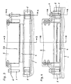
- Fig. 1
- zwei zu verbindende Bauteile in perspektivischer Ansicht, und zwar vor dem Fügevorgang,
- Fig. 2
- eine die Fig. 1 ergänzende Ansicht nach dem Fügevorgang,
- Fig. 3
- die Seitenansicht zu Fig. 1,
- Fig. 4
- die Seitenansicht zu Fig. 2,
- Fig. 5
- den Schnitt nach der Linie A - A in Fig. 3,
- Fig. 6
- den Schnitt nach der Linie A - A in Fig. 4,
- Fig. 7
- den Schnitt nach der Linie B - B in Fig. 3,
- Fig. 8
- den Schnitt nach der Linie B - B in Fig. 4.
- 1
- erstes Bauteil
- 1a
- keilförmige Nut
- 2
- zweites Bauteil
- 2a
- Steg
- 2b
- geschlitzter Endbereich
- 3
- Klebstoff
- 4
- Spreizelement
- 5
- Montagekeil
- 5a
- Beilage
- 6
- Montagewinkel
- 7
- Montageschraube
Claims (4)
- Verbindung von zwei langgestreckten Bauteilen (1, 2), insbesondere von zwei Fahrzeugträgem, aus gleichen oder unterschiedlichen Materialien, wobei einander zugewandte Flächen dieser Bauteile (1, 2) durch einen Klebstoff (3) gehalten sind, dadurch gekennzeichnet, dass eines der beiden Bauteile (1) eine keilförmig gestaltete Nut (1a) aufweist, deren Öffnungsbreite schmaler ist als ihre Fußbreite, wobei das andere Bauteil (2) mit zwei Stegen (2a) versehen ist, die in die Nut (1a) des einen Bauteils (1) eingreifen und durch Aufspreizen der Stege (2a) in formschlüssiger Wirkverbindung mit den Seitenflächen der keilförmigen Nut (1a) stehen.
- Verbindung nach Anspruch 1, dadurch gekennzeichnet, daß zwischen den beiden Stegen (2a) des zweiten Bauteils (2) ein Spreizelement (4) angeordnet ist.
- Verbindung nach Anspruch 1 oder 2, dadurch gekennzeichnet, daß das Aufspreizen der Stege (2a) des zweiten Bauteils (2) mit Hilfe von Montageschrauben (7) erfolgt, die einerseits an lösbar mit dem zweiten Bauteil (2) verbundenen Montagewinkeln (6) und andererseits gegenüber dem ersten Bauteil (1) angreifen.
- Verbindung nach Anspruch 3, dadurch gekennzeichnet, daß die Montageschrauben (7) an Montagekeilen (5) angreifen, die in der Nut (1a) des ersten Bauteils (1) fixiert sind.
Applications Claiming Priority (2)
| Application Number | Priority Date | Filing Date | Title |
|---|---|---|---|
| DE19852517 | 1998-11-13 | ||
| DE19852517A DE19852517A1 (de) | 1998-11-13 | 1998-11-13 | Verbindung von zwei Bauteilen aus gleichen oder unterschiedlichen Materialien |
Publications (3)
| Publication Number | Publication Date |
|---|---|
| EP1001177A2 EP1001177A2 (de) | 2000-05-17 |
| EP1001177A3 EP1001177A3 (de) | 2002-04-03 |
| EP1001177B1 true EP1001177B1 (de) | 2003-10-22 |
Family
ID=7887766
Family Applications (1)
| Application Number | Title | Priority Date | Filing Date |
|---|---|---|---|
| EP99122111A Expired - Lifetime EP1001177B1 (de) | 1998-11-13 | 1999-11-05 | Verbindung von zwei Bauteilen aus gleichen oder unterschiedlichen Materialien |
Country Status (5)
| Country | Link |
|---|---|
| EP (1) | EP1001177B1 (de) |
| AT (1) | ATE252690T1 (de) |
| DE (2) | DE19852517A1 (de) |
| ES (1) | ES2210946T3 (de) |
| PT (1) | PT1001177E (de) |
Family Cites Families (3)
| Publication number | Priority date | Publication date | Assignee | Title |
|---|---|---|---|---|
| FR2459398A1 (fr) * | 1979-06-15 | 1981-01-09 | Viennot Pierre | Procede d'assujettissement de tiges en materiau isolant dans des ferrures d'accrochage et dispositif pour sa realisation |
| US5664900A (en) * | 1992-05-28 | 1997-09-09 | Matthies; Klaus E. | Dowel joint system for connecting elements of a solid material |
| US5343666A (en) * | 1992-10-28 | 1994-09-06 | Ford Motor Company | Space frame joint construction |
-
1998
- 1998-11-13 DE DE19852517A patent/DE19852517A1/de not_active Withdrawn
-
1999
- 1999-11-05 AT AT99122111T patent/ATE252690T1/de not_active IP Right Cessation
- 1999-11-05 PT PT99122111T patent/PT1001177E/pt unknown
- 1999-11-05 EP EP99122111A patent/EP1001177B1/de not_active Expired - Lifetime
- 1999-11-05 ES ES99122111T patent/ES2210946T3/es not_active Expired - Lifetime
- 1999-11-05 DE DE59907436T patent/DE59907436D1/de not_active Expired - Fee Related
Also Published As
| Publication number | Publication date |
|---|---|
| EP1001177A2 (de) | 2000-05-17 |
| DE19852517A1 (de) | 2000-05-18 |
| DE59907436D1 (de) | 2003-11-27 |
| ATE252690T1 (de) | 2003-11-15 |
| ES2210946T3 (es) | 2004-07-01 |
| PT1001177E (pt) | 2004-03-31 |
| EP1001177A3 (de) | 2002-04-03 |
Similar Documents
| Publication | Publication Date | Title |
|---|---|---|
| EP1531275B1 (de) | Vorrichtung und Verfahren zur mechanischen Verbindung von zwei Bauteilen | |
| DE29712206U1 (de) | Vorrichtung zum Anschluß einer elektrischen Leitung an einem Eisenbahnschienensteg o.dgl. | |
| EP4240979A1 (de) | Profilkopplungsanordnung | |
| DE4210488A1 (de) | Verbindungseinrichtung für ein insbesondere rohrförmiges Bauteil | |
| EP1729018B1 (de) | Profilverbindungssystem | |
| DE10231250A1 (de) | System zur Verbindung und/oder Befestigung von Geländerrohren | |
| DE3518813C2 (de) | ||
| EP1001177A2 (de) | Verbindung von zwei Bauteilen aus gleichen oder unterschiedlichen Materialien | |
| DE19829795A1 (de) | Verbindung von Bauteilen aus gleichen oder unterschiedlichen Materialien | |
| DE9401970U1 (de) | Spreizbolzen | |
| EP0628736B1 (de) | Möbel mit einem Rohrgestell | |
| EP0622504B1 (de) | Knoten und Knotenanschlusselement für Gerüstbausysteme | |
| DE29820379U1 (de) | Verbindung von zwei Bauteilen aus gleichen oder unterschiedlichen Materialien | |
| EP1769160B1 (de) | Adapter zum anschluss von bauelementen untereinander und bauteil hergestellt unter verwendung eines solchen adapters | |
| DE19745685C1 (de) | Schraubverbindungen von Rahmenprofilen wie Stoß- und Dauerverbindungen | |
| DE29803308U1 (de) | Profilverbindungssystem | |
| DE9403157U1 (de) | Verbindung von Profilstäben | |
| DE20119311U1 (de) | Befestigungselement zur Verbindung plattenförmiger Bauteile | |
| DE9205483U1 (de) | Befestigungseinrichtung für eine Kamera in einem Fahrschulwagen | |
| EP1366302B1 (de) | Anordnung zum lösbaren verbinden zweier stumpf aneinander stossender bauteile | |
| DE9314824U1 (de) | Schraubverbindung | |
| DE8032795U1 (de) | Kupplung für eine lösbare, biegesteife Verbindung für Rohre, insbesondere für Konstruktionsmaste | |
| DE19522095A1 (de) | Bauteilverbindung für langgestreckte Tragglieder | |
| DE202020101578U1 (de) | Baueinheit aus einem Möbelbein, einer Tragstrebe und einem Verbindungsmechanismus | |
| DE3432194A1 (de) | Spannstift |
Legal Events
| Date | Code | Title | Description |
|---|---|---|---|
| PUAI | Public reference made under article 153(3) epc to a published international application that has entered the european phase |
Free format text: ORIGINAL CODE: 0009012 |
|
| AK | Designated contracting states |
Kind code of ref document: A2 Designated state(s): AT BE CH CY DE DK ES FI FR GB GR IE IT LI LU MC NL PT SE |
|
| AX | Request for extension of the european patent |
Free format text: AL;LT;LV;MK;RO;SI |
|
| PUAL | Search report despatched |
Free format text: ORIGINAL CODE: 0009013 |
|
| AK | Designated contracting states |
Kind code of ref document: A3 Designated state(s): AT BE CH CY DE DK ES FI FR GB GR IE IT LI LU MC NL PT SE |
|
| AX | Request for extension of the european patent |
Free format text: AL;LT;LV;MK;RO;SI |
|
| RIC1 | Information provided on ipc code assigned before grant |
Free format text: 7F 16B 11/00 A, 7F 16B 5/00 B |
|
| RAP1 | Party data changed (applicant data changed or rights of an application transferred) |
Owner name: SIEMENS AKTIENGESELLSCHAFT |
|
| 17P | Request for examination filed |
Effective date: 20020924 |
|
| AKX | Designation fees paid |
Free format text: AT BE CH CY DE DK ES FI FR GB GR IE IT LI LU MC NL PT SE |
|
| 17Q | First examination report despatched |
Effective date: 20021125 |
|
| GRAH | Despatch of communication of intention to grant a patent |
Free format text: ORIGINAL CODE: EPIDOS IGRA |
|
| GRAS | Grant fee paid |
Free format text: ORIGINAL CODE: EPIDOSNIGR3 |
|
| GRAA | (expected) grant |
Free format text: ORIGINAL CODE: 0009210 |
|
| AK | Designated contracting states |
Kind code of ref document: B1 Designated state(s): AT BE CH CY DE DK ES FI FR GB GR IE IT LI LU MC NL PT SE |
|
| PG25 | Lapsed in a contracting state [announced via postgrant information from national office to epo] |
Ref country code: NL Free format text: LAPSE BECAUSE OF FAILURE TO SUBMIT A TRANSLATION OF THE DESCRIPTION OR TO PAY THE FEE WITHIN THE PRESCRIBED TIME-LIMIT Effective date: 20031022 Ref country code: IE Free format text: LAPSE BECAUSE OF FAILURE TO SUBMIT A TRANSLATION OF THE DESCRIPTION OR TO PAY THE FEE WITHIN THE PRESCRIBED TIME-LIMIT Effective date: 20031022 Ref country code: FI Free format text: LAPSE BECAUSE OF FAILURE TO SUBMIT A TRANSLATION OF THE DESCRIPTION OR TO PAY THE FEE WITHIN THE PRESCRIBED TIME-LIMIT Effective date: 20031022 |
|
| REG | Reference to a national code |
Ref country code: GB Ref legal event code: FG4D Free format text: NOT ENGLISH |
|
| REG | Reference to a national code |
Ref country code: CH Ref legal event code: NV Representative=s name: SIEMENS SCHWEIZ AG Ref country code: CH Ref legal event code: EP |
|
| PG25 | Lapsed in a contracting state [announced via postgrant information from national office to epo] |
Ref country code: LU Free format text: LAPSE BECAUSE OF NON-PAYMENT OF DUE FEES Effective date: 20031105 Ref country code: CY Free format text: LAPSE BECAUSE OF FAILURE TO SUBMIT A TRANSLATION OF THE DESCRIPTION OR TO PAY THE FEE WITHIN THE PRESCRIBED TIME-LIMIT Effective date: 20031105 |
|
| REG | Reference to a national code |
Ref country code: IE Ref legal event code: FG4D Free format text: GERMAN |
|
| REF | Corresponds to: |
Ref document number: 59907436 Country of ref document: DE Date of ref document: 20031127 Kind code of ref document: P |
|
| PG25 | Lapsed in a contracting state [announced via postgrant information from national office to epo] |
Ref country code: MC Free format text: LAPSE BECAUSE OF NON-PAYMENT OF DUE FEES Effective date: 20031130 |
|
| PG25 | Lapsed in a contracting state [announced via postgrant information from national office to epo] |
Ref country code: GR Free format text: LAPSE BECAUSE OF FAILURE TO SUBMIT A TRANSLATION OF THE DESCRIPTION OR TO PAY THE FEE WITHIN THE PRESCRIBED TIME-LIMIT Effective date: 20040122 Ref country code: DK Free format text: LAPSE BECAUSE OF FAILURE TO SUBMIT A TRANSLATION OF THE DESCRIPTION OR TO PAY THE FEE WITHIN THE PRESCRIBED TIME-LIMIT Effective date: 20040122 |
|
| GBT | Gb: translation of ep patent filed (gb section 77(6)(a)/1977) |
Effective date: 20040106 |
|
| REG | Reference to a national code |
Ref country code: SE Ref legal event code: TRGR |
|
| REG | Reference to a national code |
Ref country code: PT Ref legal event code: SC4A Free format text: AVAILABILITY OF NATIONAL TRANSLATION Effective date: 20040122 |
|
| NLV1 | Nl: lapsed or annulled due to failure to fulfill the requirements of art. 29p and 29m of the patents act | ||
| REG | Reference to a national code |
Ref country code: IE Ref legal event code: FD4D |
|
| REG | Reference to a national code |
Ref country code: ES Ref legal event code: FG2A Ref document number: 2210946 Country of ref document: ES Kind code of ref document: T3 |
|
| ET | Fr: translation filed | ||
| PLBE | No opposition filed within time limit |
Free format text: ORIGINAL CODE: 0009261 |
|
| STAA | Information on the status of an ep patent application or granted ep patent |
Free format text: STATUS: NO OPPOSITION FILED WITHIN TIME LIMIT |
|
| 26N | No opposition filed |
Effective date: 20040723 |
|
| PGFP | Annual fee paid to national office [announced via postgrant information from national office to epo] |
Ref country code: PT Payment date: 20051018 Year of fee payment: 7 |
|
| PGFP | Annual fee paid to national office [announced via postgrant information from national office to epo] |
Ref country code: AT Payment date: 20051019 Year of fee payment: 7 |
|
| PGFP | Annual fee paid to national office [announced via postgrant information from national office to epo] |
Ref country code: SE Payment date: 20051108 Year of fee payment: 7 Ref country code: GB Payment date: 20051108 Year of fee payment: 7 |
|
| PGFP | Annual fee paid to national office [announced via postgrant information from national office to epo] |
Ref country code: BE Payment date: 20051118 Year of fee payment: 7 |
|
| PGFP | Annual fee paid to national office [announced via postgrant information from national office to epo] |
Ref country code: FR Payment date: 20051122 Year of fee payment: 7 |
|
| PGFP | Annual fee paid to national office [announced via postgrant information from national office to epo] |
Ref country code: ES Payment date: 20051214 Year of fee payment: 7 |
|
| PGFP | Annual fee paid to national office [announced via postgrant information from national office to epo] |
Ref country code: DE Payment date: 20060123 Year of fee payment: 7 |
|
| PGFP | Annual fee paid to national office [announced via postgrant information from national office to epo] |
Ref country code: CH Payment date: 20060206 Year of fee payment: 7 |
|
| PG25 | Lapsed in a contracting state [announced via postgrant information from national office to epo] |
Ref country code: AT Free format text: LAPSE BECAUSE OF NON-PAYMENT OF DUE FEES Effective date: 20061105 |
|
| PG25 | Lapsed in a contracting state [announced via postgrant information from national office to epo] |
Ref country code: SE Free format text: LAPSE BECAUSE OF NON-PAYMENT OF DUE FEES Effective date: 20061106 |
|
| PG25 | Lapsed in a contracting state [announced via postgrant information from national office to epo] |
Ref country code: LI Free format text: LAPSE BECAUSE OF NON-PAYMENT OF DUE FEES Effective date: 20061130 Ref country code: CH Free format text: LAPSE BECAUSE OF NON-PAYMENT OF DUE FEES Effective date: 20061130 Ref country code: BE Free format text: LAPSE BECAUSE OF NON-PAYMENT OF DUE FEES Effective date: 20061130 |
|
| PGFP | Annual fee paid to national office [announced via postgrant information from national office to epo] |
Ref country code: IT Payment date: 20061130 Year of fee payment: 8 |
|
| PG25 | Lapsed in a contracting state [announced via postgrant information from national office to epo] |
Ref country code: PT Free format text: LAPSE BECAUSE OF NON-PAYMENT OF DUE FEES Effective date: 20070507 |
|
| REG | Reference to a national code |
Ref country code: PT Ref legal event code: MM4A Free format text: LAPSE DUE TO NON-PAYMENT OF FEES Effective date: 20070507 |
|
| PG25 | Lapsed in a contracting state [announced via postgrant information from national office to epo] |
Ref country code: DE Free format text: LAPSE BECAUSE OF NON-PAYMENT OF DUE FEES Effective date: 20070601 |
|
| REG | Reference to a national code |
Ref country code: CH Ref legal event code: PL |
|
| EUG | Se: european patent has lapsed | ||
| GBPC | Gb: european patent ceased through non-payment of renewal fee |
Effective date: 20061105 |
|
| REG | Reference to a national code |
Ref country code: FR Ref legal event code: ST Effective date: 20070731 |
|
| PG25 | Lapsed in a contracting state [announced via postgrant information from national office to epo] |
Ref country code: GB Free format text: LAPSE BECAUSE OF NON-PAYMENT OF DUE FEES Effective date: 20061105 |
|
| BERE | Be: lapsed |
Owner name: *SIEMENS A.G. Effective date: 20061130 |
|
| REG | Reference to a national code |
Ref country code: ES Ref legal event code: FD2A Effective date: 20061106 |
|
| PG25 | Lapsed in a contracting state [announced via postgrant information from national office to epo] |
Ref country code: FR Free format text: LAPSE BECAUSE OF NON-PAYMENT OF DUE FEES Effective date: 20061130 Ref country code: ES Free format text: LAPSE BECAUSE OF NON-PAYMENT OF DUE FEES Effective date: 20061106 |
|
| PG25 | Lapsed in a contracting state [announced via postgrant information from national office to epo] |
Ref country code: IT Free format text: LAPSE BECAUSE OF NON-PAYMENT OF DUE FEES Effective date: 20071105 |