EP1001140A2 - Berstschutzring für Turbinen - Google Patents
Berstschutzring für Turbinen Download PDFInfo
- Publication number
- EP1001140A2 EP1001140A2 EP99308435A EP99308435A EP1001140A2 EP 1001140 A2 EP1001140 A2 EP 1001140A2 EP 99308435 A EP99308435 A EP 99308435A EP 99308435 A EP99308435 A EP 99308435A EP 1001140 A2 EP1001140 A2 EP 1001140A2
- Authority
- EP
- European Patent Office
- Prior art keywords
- rails
- shield
- shroud
- backsheet
- blade
- Prior art date
- Legal status (The legal status is an assumption and is not a legal conclusion. Google has not performed a legal analysis and makes no representation as to the accuracy of the status listed.)
- Granted
Links
- 238000010276 construction Methods 0.000 claims abstract description 7
- 239000002184 metal Substances 0.000 claims description 11
- 229910052751 metal Inorganic materials 0.000 claims description 11
- 230000021715 photosynthesis, light harvesting Effects 0.000 claims description 2
- 238000009420 retrofitting Methods 0.000 claims description 2
- 238000000034 method Methods 0.000 claims 1
- 239000000567 combustion gas Substances 0.000 description 5
- 239000007789 gas Substances 0.000 description 4
- 238000005219 brazing Methods 0.000 description 3
- 239000000945 filler Substances 0.000 description 2
- 239000000446 fuel Substances 0.000 description 2
- 230000003116 impacting effect Effects 0.000 description 2
- 239000012212 insulator Substances 0.000 description 2
- 239000000463 material Substances 0.000 description 2
- 229910000531 Co alloy Inorganic materials 0.000 description 1
- 230000002411 adverse Effects 0.000 description 1
- 230000005465 channeling Effects 0.000 description 1
- 230000008602 contraction Effects 0.000 description 1
- 238000005336 cracking Methods 0.000 description 1
- 230000007423 decrease Effects 0.000 description 1
- 230000000977 initiatory effect Effects 0.000 description 1
- 238000012423 maintenance Methods 0.000 description 1
- 230000000737 periodic effect Effects 0.000 description 1
- 230000008646 thermal stress Effects 0.000 description 1
Images


Classifications
-
- F—MECHANICAL ENGINEERING; LIGHTING; HEATING; WEAPONS; BLASTING
- F01—MACHINES OR ENGINES IN GENERAL; ENGINE PLANTS IN GENERAL; STEAM ENGINES
- F01D—NON-POSITIVE DISPLACEMENT MACHINES OR ENGINES, e.g. STEAM TURBINES
- F01D21/00—Shutting-down of machines or engines, e.g. in emergency; Regulating, controlling, or safety means not otherwise provided for
- F01D21/04—Shutting-down of machines or engines, e.g. in emergency; Regulating, controlling, or safety means not otherwise provided for responsive to undesired position of rotor relative to stator or to breaking-off of a part of the rotor, e.g. indicating such position
- F01D21/045—Shutting-down of machines or engines, e.g. in emergency; Regulating, controlling, or safety means not otherwise provided for responsive to undesired position of rotor relative to stator or to breaking-off of a part of the rotor, e.g. indicating such position special arrangements in stators or in rotors dealing with breaking-off of part of rotor
-
- F—MECHANICAL ENGINEERING; LIGHTING; HEATING; WEAPONS; BLASTING
- F01—MACHINES OR ENGINES IN GENERAL; ENGINE PLANTS IN GENERAL; STEAM ENGINES
- F01D—NON-POSITIVE DISPLACEMENT MACHINES OR ENGINES, e.g. STEAM TURBINES
- F01D11/00—Preventing or minimising internal leakage of working-fluid, e.g. between stages
- F01D11/08—Preventing or minimising internal leakage of working-fluid, e.g. between stages for sealing space between rotor blade tips and stator
- F01D11/12—Preventing or minimising internal leakage of working-fluid, e.g. between stages for sealing space between rotor blade tips and stator using a rubstrip, e.g. erodible. deformable or resiliently-biased part
- F01D11/127—Preventing or minimising internal leakage of working-fluid, e.g. between stages for sealing space between rotor blade tips and stator using a rubstrip, e.g. erodible. deformable or resiliently-biased part with a deformable or crushable structure, e.g. honeycomb
Definitions
- the present invention relates generally to gas turbine engines, and, more specifically, to blade containment therein.
- a typical gas turbine engine includes in serial flow communication a fan, multistage axial compressor, combustor, high pressure turbine (HPT), and low pressure turbine (LPT).
- HPT high pressure turbine
- LPT low pressure turbine
- air is pressurized in the compressor and mixed with fuel and ignited in the combustor for producing combustion gases which flow downstream through the HPT and LPT which extract energy therefrom for powering the compressor and fan, respectively, through corresponding driveshafts.
- the fan, compressor, and turbines each include differently configured rotor blades extending radially outwardly from corresponding rotors or disks which rotate during operation. For various reasons during the useful life of the engine, a rotor blade may fail and separate from its corresponding rotor disk. Centrifugal force will then propel or eject the liberated blade radially outwardly into its surrounding stator case.
- the different stator cases are configured in various manners for dissipating blade ejection energy for containing the blade and preventing its liberation from the engine.
- the various rotor blades are different in size and operate at different rotary speeds and therefore have different amounts of ejection energy when liberated.
- the different rotor blades also require different surrounding stator cases which experience different operating environments from the relatively cool environments in the fan, compressor, and LPT, to the hottest environment in the HPT.
- the cases include various forms of blade shrouds surrounding the blade tips for minimizing the clearance therewith while also permitting occasional rubs therebetween without damaging the blades.
- the blade shrouds are damaged, and when such damage accumulates, the blade shrouds are replaced in a periodic maintenance outage.
- the corresponding turbine cases are correspondingly sized in thickness for dissipating the ejection energy.
- the blade shrouds provide a significant contribution to blade containment since they are typically relatively thick, cast metal structures having substantial strength.
- LPT blade shrouds are typically uncooled, light-weight sheet metal constructions having little, if any, significant ability for dissipating ejection energy.
- a typical LPT blade shroud is an assembly of a sheet metal backsheet having a light weight honeycomb rub strip attached thereto.
- the backsheet has forward and aft rails which are suitably mounted to corresponding forward and aft mounting hooks extending radially inwardly from the case.
- the backsheet is thin sheet metal, of about 20 mils thickness for example, for minimizing the weight of the shroud yet providing sufficient rigidity for being mounted to the case and maintaining a preferred clearance with the blade tips.
- the sheet metal may be locally thickened at one or both of the rails for providing sufficient strength for attachment to the corresponding hooks.
- the backsheet may be too thin between its axially separated rails, and is reinforced using a doubler sheet, which is typically another thin piece of sheet metal brazed or otherwise fixedly attached to the outer side of the backsheet.
- the blade containing capability thereof is negligible. Since the doubler, for example, is brazed to the backsheet, the brazing filler is relatively brittle and in an blade ejection event the filler is subject to brittle cracking and decreases the strength of the shroud.
- a low pressure turbine shroud mountable to an annular case for surrounding a row of rotor blades comprising: an arcuate backsheet having forward and aft mounting rails at axially opposite ends thereof for engaging said case, and a thicker blade containment shield extending axially therebetween in a unitary construction; and a rub strip fixedly joined to a radially inner surface of said backsheet between said rails.
- the low pressure turbine shroud includes an arcuate backsheet having opposite mounting rails for engaging a surrounding annular case.
- the backsheet includes a thicker blade containment shield extending between the rails in a unitary construction. And, a honeycomb rub strip is fixedly joined to the backsheet between the rails.
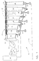
- FIG. 1 Illustrated schematically in Figure 1 is an exemplary gas turbine engine 10 which is axisymmetrical about a longitudinal or axial centerline axis 12.
- the engine includes in serial flow communication a fan 14, multistage axial compressor 16, combustor 18, high pressure turbine (HPT) 20, and low pressure turbine (LPT) 22.
- HPT high pressure turbine
- LPT low pressure turbine
- air 24 is pressurized in the compressor, mixed with fuel in the combustor and ignited for generating hot combustion gases 26 which flow downstream in turn through the HPT 20 and the LPT 22 which extract energy therefrom for powering the compressor 16 and fan 14, respectively. Since the combustion gases 26 have their greatest temperature upon discharge from the combustor, the HPT 20, including its rotor blades, stator vanes, and blade shrouds, is cooled using a portion of the compressed air 24 bled from the compressor during operation. Upon reaching the LPT 22, the combustion gases 26 have a reduced temperature, and the LPT is therefore typically uncooled.
- the exemplary multistage LPT 22 illustrated in Figure 1 includes several rows of rotor blades 28 extending radially outwardly from corresponding rotor disks 30 which are interconnected and joined to a common driveshaft for powering the fan 14 during operation.
- the LPT also includes an annular casing or case 32 from which extends radially inwardly corresponding nozzles in the form of rows of stator vanes 34 which cooperate with corresponding ones of the blade rows for channeling the combustion gases therethrough.
- one or more rows of LPT blade shrouds 36 are also mounted to the case 32 for surrounding a respective row of the rotor blades 28 for use in blade containment thereof in the event of a blade ejection event.
- an exemplary one of the rotor blades 28 may fail during operation and separate from its supporting disk 30, with centrifugal force F propelling or ejecting the liberated blade radially outwardly for firstly impacting the surrounding blade shroud 36 and then impacting the surrounding case 32.
- each blade shroud 36 is preferably formed in a plurality of circumferentially adjoining arcuate segments which collectively form a complete ring around the radially outer tips of a blade row.
- the shroud includes an arcuate backsheet 38 having a first or forward mounting rail 40 and a second or aft mounting rail 42 disposed at axially opposite ends thereof for engaging the case 32.
- the backsheet also includes an integral blade containment shield 44 extending axially between the two rails 40,42 in a unitary or one-piece construction. The shield portion of the backsheet is selectively thicker than each of the rails for dissipating blade ejection energy for cooperating with the case in blade containment of the ejected blade.
- the blade shroud 36 also includes a honeycomb rub strip 46 fixedly joined or bonded directly to the radially inner surface of the backsheet 38 axially between the two rails 40,42.
- the rub strip may take any conventional form and extends the full circumferential length of each of the backsheet segments.
- the rub strip 46 has a suitable height so that its radially inner surface may be suitably spaced from the blade tips to provide a clearance gap therebetween.
- the shield 44 extends both axially between the two rails 40,42 and circumferentially therealong over the full arcuate extent of the segment for being aligned directly over the blade tips illustrated in Figure 2.
- the shield is sized in thickness for dissipating energy upon ejection of one of the blades 28 thereagainst in a failure event.
- the shield is preferably continuous axially along the rails 40,42 and circumferentially therealong, with a substantially constant thickness A.
- the shield 44 may be in the form of a plurality of axially spaced apart, circumferentially extending ribs having reduced weight while providing blade containment capability.
- the containment shield 44 is selectively thickened relative to the remainder of the backsheet 38 for also reducing overall weight, while effectively locating blade containment material.
- the containment shield 44 preferably extends radially outwardly from both rails 40,42 to avoid changing the thickness of the rub strip 46.
- the radially inner surface of the backsheet 38 is preferably recessed radially outwardly from at least one of the two rails such as the aft rail 42.
- the forward rail 40 is flush with the recessed inner surface of the shield 44 and has a minimum thickness B suitable for mounting the forward end of the shroud to the casing.
- the aft rail 42 has a larger thickness C selected for supporting the aft end of the shroud to the case 32.
- the case 32 includes integral forward and aft hooks 48,50 extending radially inwardly and axially spaced apart to engage or mount the forward and aft rails 40,42, respectively.
- Suitable means are provided for retaining the rails on the hooks in a locked arrangement.
- a generally U-shaped, sheet metal forward clip 52 is attached, by brazing for example, to the top of the forward rail 40 for axially engaging the tip end of the forward hook 48.
- the aft rail 42 is attached in radial abutment against the aft hook by a corresponding generally U-shaped aft clip 54 formed at the forward end of the radially outer band of the adjacent nozzle vanes 34.
- the aft rail 42 is thicker than the forward rail 40, and the shield 44 is thicker than the aft rail 42 as well as the forward rail 40.
- This configuration selectively minimizes the thicknesses B, C of the forward and aft rails 40,42 as required for mounting the shroud 36 to the corresponding case hooks 48,50, while providing a selectively thickened middle region therebetween in the form of the unitary containment shield portion.
- the backsheet 38 is a unitary or one-piece sheet metal construction formed of any suitable metal for the LPT environment, such as conventional HS 188 which is a cobalt alloy.
- the containment shield 44 is preferably at least thrice as thick as the forward rail 40, with the forward rail being about 20 mils thick, the aft rail 42 being about 40 mils thick, and the containment shield 44 being about 60 mils thick in one example.
- the rails are thinner than the center shield portion of the backsheet 38, only the shield portion is disposed radially outwardly of the rotor blades 28 and is interposed between the case 32 for providing additional blade containment capability.
- the improved blade containment shrouds 36 cooperate with the surrounding case 32 for collectively providing blade containment capability.
- the case 32 between the hooks 48,50 has a thickness D and is disposed radially outwardly of the inner shield 44, itself having a thickness A.
- the combined material of the shield 44 and the case 32 radially outwardly of the blades 28 collectively provide for energy dissipation of an ejected blade for blade containment thereof, and preventing liberation from the case of most if not all of the liberated blade.
- annular thermal insulator 56 is disposed in the available space between the case 32 and the shield 44 for controlling thermal expansion and contraction in this region for minimizing variation in the blade tip gap during operation.
- the insulator however, has negligible blade containment capability, with blade containment being primarily provided by the relatively thick case 32 and the cooperating containment shield 44.
- blade containment shrouds 36 may be configured in an otherwise conventional configuration except for the introduction of the selectively thickened backsheet 38 for effecting blade containment capability.
- This configuration therefore allows the retrofitting of the LPT 22 for increasing blade containment capability or strength thereof by substituting or replacing the thicker shroud 36 for a thinner conventional shroud therein without changing thickness of the case 32, and without changing geometry of the supporting hooks and remainder of the individual shrouds 36 but for the shield 44. Since turbine shrouds are normally replaced on a routine basis due to normal blade tip rubs, old-design turbine shrouds may be simply replaced with the improved blade containment shrouds 36 within the available space, and without any other changes in the shroud design.
- the thicker containment shield portion of the backsheet 38 is unitary sheet metal without brazing or other attachment for achieving the increased thickness to maximize blade containment strength without introducing any undesirable brittleness or crack initiation sites.
- the increased thickness of the backsheet 38 does not introduce undesirable thermal gradients therein during operation which could adversely affect both aerodynamic efficiency by varying the desired radial tip clearance, or introduce undesirable thermal stresses which could affect fatigue life.
Landscapes
- Engineering & Computer Science (AREA)
- Mechanical Engineering (AREA)
- General Engineering & Computer Science (AREA)
- Turbine Rotor Nozzle Sealing (AREA)
Applications Claiming Priority (2)
| Application Number | Priority Date | Filing Date | Title |
|---|---|---|---|
| US09/191,659 US6120242A (en) | 1998-11-13 | 1998-11-13 | Blade containing turbine shroud |
| US191659 | 1998-11-13 |
Publications (3)
| Publication Number | Publication Date |
|---|---|
| EP1001140A2 true EP1001140A2 (de) | 2000-05-17 |
| EP1001140A3 EP1001140A3 (de) | 2001-10-04 |
| EP1001140B1 EP1001140B1 (de) | 2007-05-30 |
Family
ID=22706390
Family Applications (1)
| Application Number | Title | Priority Date | Filing Date |
|---|---|---|---|
| EP99308435A Expired - Lifetime EP1001140B1 (de) | 1998-11-13 | 1999-10-26 | Berstschutzring für Turbinen |
Country Status (4)
| Country | Link |
|---|---|
| US (2) | US6120242A (de) |
| EP (1) | EP1001140B1 (de) |
| JP (1) | JP4495283B2 (de) |
| DE (1) | DE69936176T2 (de) |
Cited By (7)
| Publication number | Priority date | Publication date | Assignee | Title |
|---|---|---|---|---|
| WO2004061340A1 (de) * | 2002-12-20 | 2004-07-22 | Mtu Aero Engines Gmbh | Wabendichtung |
| CN103422913A (zh) * | 2013-08-29 | 2013-12-04 | 哈尔滨工程大学 | 一种带有蜂窝状内壁机匣的涡轮 |
| EP2811122A1 (de) * | 2013-06-07 | 2014-12-10 | MTU Aero Engines GmbH | Turbinengehäuse mit Verstärkungselementen im Containmentbereich |
| EP2813671A1 (de) * | 2013-05-29 | 2014-12-17 | Mitsubishi Hitachi Power Systems, Ltd. | Gasturbine mit Wabendichtung |
| EP3153671A1 (de) * | 2015-10-08 | 2017-04-12 | MTU Aero Engines GmbH | Schutzvorrichtung für eine strömungsmaschine |
| EP3170990A1 (de) * | 2015-11-20 | 2017-05-24 | United Technologies Corporation | Äussere luftdichtung für gasturbinenmotor |
| FR3072713A1 (fr) * | 2017-10-23 | 2019-04-26 | Safran Aircraft Engines | Secteur d'anneau de turbine pour turbomachine d'aeronef |
Families Citing this family (41)
| Publication number | Priority date | Publication date | Assignee | Title |
|---|---|---|---|---|
| US6341938B1 (en) * | 2000-03-10 | 2002-01-29 | General Electric Company | Methods and apparatus for minimizing thermal gradients within turbine shrouds |
| US6547522B2 (en) * | 2001-06-18 | 2003-04-15 | General Electric Company | Spring-backed abradable seal for turbomachinery |
| US6893217B2 (en) * | 2002-12-20 | 2005-05-17 | General Electric Company | Methods and apparatus for assembling gas turbine nozzles |
| US6892931B2 (en) * | 2002-12-27 | 2005-05-17 | General Electric Company | Methods for replacing portions of turbine shroud supports |
| US7094029B2 (en) * | 2003-05-06 | 2006-08-22 | General Electric Company | Methods and apparatus for controlling gas turbine engine rotor tip clearances |
| GB2407343B (en) * | 2003-10-22 | 2006-04-19 | Rolls Royce Plc | An acoustic liner for a gas turbine engine casing |
| GB2407344B (en) * | 2003-10-22 | 2006-02-22 | Rolls Royce Plc | A liner for a gas turbine engine casing |
| US7334984B1 (en) | 2003-12-24 | 2008-02-26 | Heico Corporation | Turbine shroud assembly with enhanced blade containment capabilities |
| DE102004010236A1 (de) * | 2004-03-03 | 2005-09-15 | Mtu Aero Engines Gmbh | Ringstruktur in Metallbauweise |
| GB0408825D0 (en) * | 2004-04-20 | 2004-05-26 | Rolls Royce Plc | A rotor blade containment assembly for a gas turbine engine |
| US7147429B2 (en) * | 2004-09-16 | 2006-12-12 | General Electric Company | Turbine assembly and turbine shroud therefor |
| GB2429043B (en) * | 2005-08-13 | 2008-02-13 | Rolls Royce Plc | Clip |
| FR2899274B1 (fr) * | 2006-03-30 | 2012-08-17 | Snecma | Dispositif de fixation de secteurs d'anneau autour d'une roue de turbine d'une turbomachine |
| GB2459646B (en) * | 2008-04-28 | 2011-03-30 | Rolls Royce Plc | A fan assembly |
| US8608424B2 (en) * | 2009-10-09 | 2013-12-17 | General Electric Company | Contoured honeycomb seal for a turbomachine |
| FR2961848B1 (fr) * | 2010-06-29 | 2012-07-13 | Snecma | Etage de turbine |
| US8511971B2 (en) | 2010-07-23 | 2013-08-20 | Hamilton Sundstrand Corporation | One-piece compressor and turbine containment system |
| GB201020143D0 (en) | 2010-11-29 | 2011-01-12 | Rolls Royce Plc | A gas turbine engine blade containment arrangement |
| US9121301B2 (en) * | 2012-03-20 | 2015-09-01 | General Electric Company | Thermal isolation apparatus |
| US9574455B2 (en) * | 2012-07-16 | 2017-02-21 | United Technologies Corporation | Blade outer air seal with cooling features |
| US9506367B2 (en) * | 2012-07-20 | 2016-11-29 | United Technologies Corporation | Blade outer air seal having inward pointing extension |
| US20140064969A1 (en) * | 2012-08-29 | 2014-03-06 | Dmitriy A. Romanov | Blade outer air seal |
| US9238977B2 (en) | 2012-11-21 | 2016-01-19 | General Electric Company | Turbine shroud mounting and sealing arrangement |
| US9651059B2 (en) | 2012-12-27 | 2017-05-16 | United Technologies Corporation | Adhesive pattern for fan case conformable liner |
| US10024191B2 (en) | 2013-03-11 | 2018-07-17 | Rolls-Royce Corporation | Fan track liner designed to yield next to fan case hook |
| US20140271142A1 (en) | 2013-03-14 | 2014-09-18 | General Electric Company | Turbine Shroud with Spline Seal |
| EP2824277B1 (de) * | 2013-07-12 | 2016-03-23 | MTU Aero Engines GmbH | Gasturbinenstufe |
| US10408080B2 (en) | 2013-10-07 | 2019-09-10 | United Technologies Corporation | Tailored thermal control system for gas turbine engine blade outer air seal array |
| EP2881545B1 (de) * | 2013-12-04 | 2017-05-31 | MTU Aero Engines GmbH | Dichtelement, Dichteinrichtung und Strömungsmaschine |
| EP2902592B1 (de) * | 2014-01-31 | 2017-04-12 | Rolls-Royce plc | Gasturbinenantrieb |
| US11421627B2 (en) * | 2017-02-22 | 2022-08-23 | General Electric Company | Aircraft and direct drive engine under wing installation |
| US10487684B2 (en) | 2017-03-31 | 2019-11-26 | The Boeing Company | Gas turbine engine fan blade containment systems |
| US10550718B2 (en) | 2017-03-31 | 2020-02-04 | The Boeing Company | Gas turbine engine fan blade containment systems |
| US10753222B2 (en) | 2017-09-11 | 2020-08-25 | Raytheon Technologies Corporation | Gas turbine engine blade outer air seal |
| US10883377B2 (en) * | 2017-10-27 | 2021-01-05 | Rolls-Royce North American Technolgies Inc. | System and method of controlling tip clearance in a shroud assembly for a bladed disc |
| US20200011203A1 (en) * | 2018-07-06 | 2020-01-09 | General Electric Company | Blade containment structure |
| US10724403B2 (en) * | 2018-07-16 | 2020-07-28 | Raytheon Technologies Corporation | Fan case assembly for gas turbine engine |
| US11319833B2 (en) | 2020-04-24 | 2022-05-03 | General Electric Company | Fan case with crack-arresting backsheet structure and removable containment cartridge |
| US11674396B2 (en) | 2021-07-30 | 2023-06-13 | General Electric Company | Cooling air delivery assembly |
| US11674405B2 (en) | 2021-08-30 | 2023-06-13 | General Electric Company | Abradable insert with lattice structure |
| US20230399981A1 (en) * | 2022-06-09 | 2023-12-14 | Pratt & Whitney Canada Corp. | Containment assembly for an aircraft engine |
Citations (5)
| Publication number | Priority date | Publication date | Assignee | Title |
|---|---|---|---|---|
| FR1223925A (fr) * | 1959-05-12 | 1960-06-21 | Gen Electric | Dispositif de limitation de vitesse pour les turbines |
| US3928963A (en) * | 1974-11-04 | 1975-12-30 | Gen Motors Corp | Cast in place gas turbine containment ring and method of manufacture |
| US4566700A (en) * | 1982-08-09 | 1986-01-28 | United Technologies Corporation | Abrasive/abradable gas path seal system |
| US5622472A (en) * | 1994-12-21 | 1997-04-22 | Societe Hispano-Suiza | Protective shield for a turbo-engine |
| US5791871A (en) * | 1996-12-18 | 1998-08-11 | United Technologies Corporation | Turbine engine rotor assembly blade outer air seal |
Family Cites Families (21)
| Publication number | Priority date | Publication date | Assignee | Title |
|---|---|---|---|---|
| US4009568A (en) * | 1975-10-30 | 1977-03-01 | General Motors Corporation | Turbine support structure |
| US4053254A (en) * | 1976-03-26 | 1977-10-11 | United Technologies Corporation | Turbine case cooling system |
| US4127357A (en) * | 1977-06-24 | 1978-11-28 | General Electric Company | Variable shroud for a turbomachine |
| DE2907748A1 (de) * | 1979-02-28 | 1980-09-04 | Motoren Turbinen Union | Einrichtung zur minimierung und konstanthaltung der bei axialturbinen vorhandenen schaufelspitzenspiele, insbesondere fuer gasturbinentriebwerke |
| GB2087979B (en) * | 1980-11-22 | 1984-02-22 | Rolls Royce | Gas turbine engine blade tip seal |
| US4417848A (en) * | 1982-02-01 | 1983-11-29 | United Technologies Corporation | Containment shell for a fan section of a gas turbine engine |
| US4784569A (en) * | 1986-01-10 | 1988-11-15 | General Electric Company | Shroud means for turbine rotor blade tip clearance control |
| JP2624661B2 (ja) * | 1987-01-07 | 1997-06-25 | 株式会社日立製作所 | ガスタービンエンジンのシール装置 |
| US4867639A (en) * | 1987-09-22 | 1989-09-19 | Allied-Signal Inc. | Abradable shroud coating |
| US4856963A (en) * | 1988-03-23 | 1989-08-15 | United Technologies Corporation | Stator assembly for an axial flow rotary machine |
| FR2635562B1 (fr) * | 1988-08-18 | 1993-12-24 | Snecma | Anneau de stator de turbine associe a un support de liaison au carter de turbine |
| JPH02298604A (ja) * | 1989-05-11 | 1990-12-11 | Toshiba Corp | 軸流々体機械の翼端漏洩防止装置 |
| IE67360B1 (en) * | 1990-09-25 | 1996-03-20 | United Technologies Corp | Apparatus and method for a stator assembly of a rotary machine |
| US5160248A (en) * | 1991-02-25 | 1992-11-03 | General Electric Company | Fan case liner for a gas turbine engine with improved foreign body impact resistance |
| US5201846A (en) * | 1991-11-29 | 1993-04-13 | General Electric Company | Low-pressure turbine heat shield |
| DE4331060C1 (de) * | 1993-09-13 | 1994-06-30 | Gruenzweig & Hartmann Montage | Wärmedämmanordnung |
| US5423659A (en) * | 1994-04-28 | 1995-06-13 | United Technologies Corporation | Shroud segment having a cut-back retaining hook |
| US5431532A (en) * | 1994-05-20 | 1995-07-11 | General Electric Company | Blade containment system |
| US5474417A (en) * | 1994-12-29 | 1995-12-12 | United Technologies Corporation | Cast casing treatment for compressor blades |
| US5538393A (en) * | 1995-01-31 | 1996-07-23 | United Technologies Corporation | Turbine shroud segment with serpentine cooling channels having a bend passage |
| GB2310255B (en) * | 1996-02-13 | 1999-06-16 | Rolls Royce Plc | A turbomachine |
-
1998
- 1998-11-13 US US09/191,659 patent/US6120242A/en not_active Expired - Lifetime
-
1999
- 1999-10-26 DE DE69936176T patent/DE69936176T2/de not_active Expired - Lifetime
- 1999-10-26 EP EP99308435A patent/EP1001140B1/de not_active Expired - Lifetime
- 1999-11-12 JP JP32186699A patent/JP4495283B2/ja not_active Expired - Fee Related
-
2000
- 2000-09-18 US US09/664,145 patent/US6468026B1/en not_active Expired - Lifetime
Patent Citations (5)
| Publication number | Priority date | Publication date | Assignee | Title |
|---|---|---|---|---|
| FR1223925A (fr) * | 1959-05-12 | 1960-06-21 | Gen Electric | Dispositif de limitation de vitesse pour les turbines |
| US3928963A (en) * | 1974-11-04 | 1975-12-30 | Gen Motors Corp | Cast in place gas turbine containment ring and method of manufacture |
| US4566700A (en) * | 1982-08-09 | 1986-01-28 | United Technologies Corporation | Abrasive/abradable gas path seal system |
| US5622472A (en) * | 1994-12-21 | 1997-04-22 | Societe Hispano-Suiza | Protective shield for a turbo-engine |
| US5791871A (en) * | 1996-12-18 | 1998-08-11 | United Technologies Corporation | Turbine engine rotor assembly blade outer air seal |
Cited By (11)
| Publication number | Priority date | Publication date | Assignee | Title |
|---|---|---|---|---|
| WO2004061340A1 (de) * | 2002-12-20 | 2004-07-22 | Mtu Aero Engines Gmbh | Wabendichtung |
| DE10259963B4 (de) * | 2002-12-20 | 2010-04-01 | Mtu Aero Engines Gmbh | Wabendichtung |
| EP2813671A1 (de) * | 2013-05-29 | 2014-12-17 | Mitsubishi Hitachi Power Systems, Ltd. | Gasturbine mit Wabendichtung |
| US9822659B2 (en) | 2013-05-29 | 2017-11-21 | Mitsubishi Hitachi Power Systems, Ltd. | Gas turbine with honeycomb seal |
| EP2811122A1 (de) * | 2013-06-07 | 2014-12-10 | MTU Aero Engines GmbH | Turbinengehäuse mit Verstärkungselementen im Containmentbereich |
| CN103422913A (zh) * | 2013-08-29 | 2013-12-04 | 哈尔滨工程大学 | 一种带有蜂窝状内壁机匣的涡轮 |
| EP3153671A1 (de) * | 2015-10-08 | 2017-04-12 | MTU Aero Engines GmbH | Schutzvorrichtung für eine strömungsmaschine |
| US10533449B2 (en) | 2015-10-08 | 2020-01-14 | MTU Aero Engines AG | Containment for a continuous flow machine |
| EP3170990A1 (de) * | 2015-11-20 | 2017-05-24 | United Technologies Corporation | Äussere luftdichtung für gasturbinenmotor |
| US10197069B2 (en) | 2015-11-20 | 2019-02-05 | United Technologies Corporation | Outer airseal for gas turbine engine |
| FR3072713A1 (fr) * | 2017-10-23 | 2019-04-26 | Safran Aircraft Engines | Secteur d'anneau de turbine pour turbomachine d'aeronef |
Also Published As
| Publication number | Publication date |
|---|---|
| EP1001140B1 (de) | 2007-05-30 |
| DE69936176D1 (de) | 2007-07-12 |
| JP4495283B2 (ja) | 2010-06-30 |
| EP1001140A3 (de) | 2001-10-04 |
| JP2000257402A (ja) | 2000-09-19 |
| US6120242A (en) | 2000-09-19 |
| DE69936176T2 (de) | 2008-01-17 |
| US6468026B1 (en) | 2002-10-22 |
Similar Documents
| Publication | Publication Date | Title |
|---|---|---|
| EP1001140B1 (de) | Berstschutzring für Turbinen | |
| EP0974733B1 (de) | Turbinenleitgitter mit einem Kühlluftleitsystem | |
| JP4733876B2 (ja) | 時計方向にずらしたタービン翼形部の冷却 | |
| US7217089B2 (en) | Gas turbine engine shroud sealing arrangement | |
| EP1939411B1 (de) | Freitragende Düse mit gekröpftem Flansch zur Hinauszögerung der Ermüdung durch niedrige Lastspielzahl | |
| EP1004759B1 (de) | Gekühltes Turbinengehäuse | |
| US8292573B2 (en) | Flange cooled turbine nozzle | |
| CA2613790C (en) | Crowned rails for supporting arcuate components | |
| EP1024251B1 (de) | Gekühlter Turbinen-Mantelring | |
| EP2098690B1 (de) | Durchlasshindernis für eine verbesserte Einlasskühlmittelfüllung | |
| US5863183A (en) | High temperature rotor blade attachment | |
| US5645399A (en) | Gas turbine engine case coated with thermal barrier coating to control axial airfoil clearance | |
| US6422819B1 (en) | Cooled airfoil for gas turbine engine and method of making the same | |
| EP1424467A2 (de) | Turbinenschaufelreihe bestehend aus Schaufeln mit langer und kurzer Sehnenlänge | |
| WO2011005337A1 (en) | Composite turbine nozzle segment | |
| WO2011005336A1 (en) | Composite nozzle segment and support frame assembly | |
| US20180142564A1 (en) | Combined turbine nozzle and shroud deflection limiter | |
| US6957948B2 (en) | Turbine blade attachment lightening holes |
Legal Events
| Date | Code | Title | Description |
|---|---|---|---|
| PUAI | Public reference made under article 153(3) epc to a published international application that has entered the european phase |
Free format text: ORIGINAL CODE: 0009012 |
|
| AK | Designated contracting states |
Kind code of ref document: A2 Designated state(s): AT BE CH CY DE DK ES FI FR GB GR IE IT LI LU MC NL PT SE Kind code of ref document: A2 Designated state(s): DE FR GB IT |
|
| AX | Request for extension of the european patent |
Free format text: AL;LT;LV;MK;RO;SI |
|
| PUAL | Search report despatched |
Free format text: ORIGINAL CODE: 0009013 |
|
| AK | Designated contracting states |
Kind code of ref document: A3 Designated state(s): AT BE CH CY DE DK ES FI FR GB GR IE IT LI LU MC NL PT SE |
|
| AX | Request for extension of the european patent |
Free format text: AL;LT;LV;MK;RO;SI |
|
| 17P | Request for examination filed |
Effective date: 20020404 |
|
| AKX | Designation fees paid |
Free format text: DE FR GB IT |
|
| 17Q | First examination report despatched |
Effective date: 20020702 |
|
| GRAP | Despatch of communication of intention to grant a patent |
Free format text: ORIGINAL CODE: EPIDOSNIGR1 |
|
| GRAS | Grant fee paid |
Free format text: ORIGINAL CODE: EPIDOSNIGR3 |
|
| GRAA | (expected) grant |
Free format text: ORIGINAL CODE: 0009210 |
|
| AK | Designated contracting states |
Kind code of ref document: B1 Designated state(s): DE FR GB IT |
|
| REG | Reference to a national code |
Ref country code: GB Ref legal event code: FG4D |
|
| REF | Corresponds to: |
Ref document number: 69936176 Country of ref document: DE Date of ref document: 20070712 Kind code of ref document: P |
|
| ET | Fr: translation filed | ||
| PLBE | No opposition filed within time limit |
Free format text: ORIGINAL CODE: 0009261 |
|
| STAA | Information on the status of an ep patent application or granted ep patent |
Free format text: STATUS: NO OPPOSITION FILED WITHIN TIME LIMIT |
|
| 26N | No opposition filed |
Effective date: 20080303 |
|
| REG | Reference to a national code |
Ref country code: FR Ref legal event code: PLFP Year of fee payment: 17 |
|
| PGFP | Annual fee paid to national office [announced via postgrant information from national office to epo] |
Ref country code: GB Payment date: 20151027 Year of fee payment: 17 Ref country code: DE Payment date: 20151028 Year of fee payment: 17 Ref country code: IT Payment date: 20151026 Year of fee payment: 17 |
|
| PGFP | Annual fee paid to national office [announced via postgrant information from national office to epo] |
Ref country code: FR Payment date: 20151019 Year of fee payment: 17 |
|
| REG | Reference to a national code |
Ref country code: DE Ref legal event code: R119 Ref document number: 69936176 Country of ref document: DE |
|
| GBPC | Gb: european patent ceased through non-payment of renewal fee |
Effective date: 20161026 |
|
| REG | Reference to a national code |
Ref country code: FR Ref legal event code: ST Effective date: 20170630 |
|
| PG25 | Lapsed in a contracting state [announced via postgrant information from national office to epo] |
Ref country code: FR Free format text: LAPSE BECAUSE OF NON-PAYMENT OF DUE FEES Effective date: 20161102 Ref country code: GB Free format text: LAPSE BECAUSE OF NON-PAYMENT OF DUE FEES Effective date: 20161026 Ref country code: DE Free format text: LAPSE BECAUSE OF NON-PAYMENT OF DUE FEES Effective date: 20170503 |
|
| PG25 | Lapsed in a contracting state [announced via postgrant information from national office to epo] |
Ref country code: IT Free format text: LAPSE BECAUSE OF NON-PAYMENT OF DUE FEES Effective date: 20161026 |