EP1000874A2 - Pressurized container - Google Patents
Pressurized container Download PDFInfo
- Publication number
- EP1000874A2 EP1000874A2 EP99810948A EP99810948A EP1000874A2 EP 1000874 A2 EP1000874 A2 EP 1000874A2 EP 99810948 A EP99810948 A EP 99810948A EP 99810948 A EP99810948 A EP 99810948A EP 1000874 A2 EP1000874 A2 EP 1000874A2
- Authority
- EP
- European Patent Office
- Prior art keywords
- valve plate
- insert
- pressure vessel
- ring
- vessel according
- Prior art date
- Legal status (The legal status is an assumption and is not a legal conclusion. Google has not performed a legal analysis and makes no representation as to the accuracy of the status listed.)
- Granted
Links
Images


Classifications
-
- B—PERFORMING OPERATIONS; TRANSPORTING
- B65—CONVEYING; PACKING; STORING; HANDLING THIN OR FILAMENTARY MATERIAL
- B65D—CONTAINERS FOR STORAGE OR TRANSPORT OF ARTICLES OR MATERIALS, e.g. BAGS, BARRELS, BOTTLES, BOXES, CANS, CARTONS, CRATES, DRUMS, JARS, TANKS, HOPPERS, FORWARDING CONTAINERS; ACCESSORIES, CLOSURES, OR FITTINGS THEREFOR; PACKAGING ELEMENTS; PACKAGES
- B65D83/00—Containers or packages with special means for dispensing contents
- B65D83/14—Containers or packages with special means for dispensing contents for delivery of liquid or semi-liquid contents by internal gaseous pressure, i.e. aerosol containers comprising propellant for a product delivered by a propellant
- B65D83/38—Details of the container body
-
- B—PERFORMING OPERATIONS; TRANSPORTING
- B65—CONVEYING; PACKING; STORING; HANDLING THIN OR FILAMENTARY MATERIAL
- B65D—CONTAINERS FOR STORAGE OR TRANSPORT OF ARTICLES OR MATERIALS, e.g. BAGS, BARRELS, BOTTLES, BOXES, CANS, CARTONS, CRATES, DRUMS, JARS, TANKS, HOPPERS, FORWARDING CONTAINERS; ACCESSORIES, CLOSURES, OR FITTINGS THEREFOR; PACKAGING ELEMENTS; PACKAGES
- B65D83/00—Containers or packages with special means for dispensing contents
- B65D83/14—Containers or packages with special means for dispensing contents for delivery of liquid or semi-liquid contents by internal gaseous pressure, i.e. aerosol containers comprising propellant for a product delivered by a propellant
- B65D83/68—Dispensing two or more contents, e.g. sequential dispensing or simultaneous dispensing of two or more products without mixing them
- B65D83/682—Dispensing two or more contents, e.g. sequential dispensing or simultaneous dispensing of two or more products without mixing them the products being first separated, but finally mixed, e.g. in a dispensing head
Abstract
Description
Die Erfindung betrifft einen Druckbehälter nach dem Oberbegriff des Anspruchs 1
bzw. des Anspruchs 2.The invention relates to a pressure vessel according to the preamble of claim 1
or
Derartige Druckbehälter sind bekannt und werden in verschiedensten Anwendungsbereichen, beispielsweise zur Aufnahme und Lagerung von sogenannten 2-K-Produkten, eingesetzt. Wichtig bei Druckbehältern zur Aufnahme von derartigen Produkten ist, dass die Produkte langzeitstabil darin aufbewahrt werden können. Dabei soll sichergestellt sein, dass die Produkte auch während einem Zeitraum von mehreren Monaten bis zu einigen Jahren im Druckbehälter aufgenommen sein können, ohne dass die Gefahr besteht, dass sich der Druck abbaut oder dass die Komponenten unter dem Einfluss von Luftfeuchtigkeit und/oder Sauerstoff chemisch reagieren.Such pressure vessels are known and are used in a wide variety of applications, for example for the reception and storage of so-called 2-component products, used. Important for pressure vessels to hold such products is that the products can be stored in it for long-term stability. Here It should be ensured that the products are also used for a period of several Can be stored in the pressure vessel for months to a few years, without the risk that the pressure is released or that the components react chemically under the influence of air humidity and / or oxygen.
Sollen im Druckbehälter Materialien mit guten adhäsiven Eigenschaften, beispielsweise Klebstoffe, aufgenommen werden, so muss die Ventilplatte zusammen mit den Abgabeventilen aus einem Material gefertigt werden, welches verhindert, dass die im Druckbehälter aufgenommenen Komponenten an den Abgabeventilen kleben bleiben und diese zusetzen. Wenn jedoch die Ventilplatte aus einem Material mit schlechten adhäsiven Eigenschaften besteht, so ist es schwierig, die Ventilplatte langzeitstabil abzudichten, da eine solche Ventilplatte bisher kaum mit dem Einsatz verklebt werden konnte. Ein zuverlässiges, langzeitstabiles Abdichten ist jedoch bei gattungsgemässen Druckbehältern unabdingbar.For example, materials with good adhesive properties should be in the pressure vessel Adhesives are added, so the valve plate together with the Dispensing valves are made from a material that prevents the im Glue the pressure vessel components to the dispensing valves stay and clog them. However, if the valve plate is made of one material poor adhesive properties exist, so it is difficult to valve plate to seal long-term, since such a valve plate has so far hardly been used could be glued. A reliable, long-term stable sealing is however with generic pressure vessels indispensable.
Aus der EP 111 089 ist ein gattungsgemässer Druckbehälter bekannt, bei dem zur Abdichtung der Ventilplatte eine Dichtung zwischen Einsatz und Ventilplatte vorgesehen ist. Um die Ventilplatte am Einsatz fixieren zu können, ist diese mit einer Ausnehmung versehen, die auf der Oberseite von einem verbreiterten Randbereich begrenzt wird. Die aus einem elastischen Material gefertigte Ventilplatte ist von unten her so in den Einsatz eingeschoben, dass der Randbereich die obere Kante des Einsatzes übergreift und der Einsatz in der Ausnehmung fixiert ist. Die Dichtung ist auf einem Absatz der Ventilplatte abgestützt und liegt an der Unterseite des Einsatzes an. Es hat sich in der Praxis gezeigt, dass mit einer derartigen Abdichtung zwischen Einsatz und Ventilplatte die aufgenommenen und ggf. unter Überdruck stehenden Komponenten, insbesondere gasförmige Stoffe, nicht über einen genügend langen Zeitraum gegenüber der Umgebungsluft abgedichtet werden können. From EP 111 089 a generic pressure vessel is known in which for Sealing the valve plate, a seal is provided between the insert and the valve plate is. In order to be able to fix the valve plate to the insert, this is with a recess provided, which is bordered on the top by a widened edge area becomes. The valve plate made of an elastic material is from below inserted into the insert so that the edge area is the upper edge of the Insert overlaps and the insert is fixed in the recess. The seal is supported on a shoulder of the valve plate and lies on the underside of the insert on. It has been shown in practice that with such a seal between the insert and the valve plate and, if necessary, under overpressure standing components, especially gaseous substances, do not have enough can be sealed against the ambient air for a long period of time.
Es ist daher die Aufgabe der Erfindung, einen Druckbehälter gemäss dem Oberbegriff
des Anspruchs 1 bzw. des Anspruchs 2 derart zu verbessern, dass dieser universell
einsetzbar ist und der Inhalt langzeitstabil gelagert werden kann.It is therefore the object of the invention to provide a pressure vessel according to the preamble
of claim 1 or
Diese Aufgabe wird durch die im Kennzeichen des Anspruchs 1 oder alternativ durch
die im Kennzeichen des Anspruchs 2 angeführten Merkmale gelöst.This object is achieved by the in the characterizing part of claim 1 or alternatively
solved the features stated in the characterizing part of
Weitere Probleme in Bezug auf die Abdichtung haben sich auch an den Dichtflächen der Abgabeventile sowie an der Befestigungsstelle des Sekundärbehälters, der an einem Stutzen der Ventilplatte befestigt ist, ergeben. Ersteres Problem entsteht dadurch, dass die einstückig ausgebildeten Abgabeventile die Ventilplatte an den Dichtflächen nicht genügend abdichten können, was einerseits auf die Oberflächen-Rauhigkeit der Ventilplatte und andererseits auf das zwangsläufig relativ harte Grundmaterial der Abgabeventile zurückzuführen ist. Das Abdichten des Sekundärbehälters mit einer in eine Ringnut eingeführten Dichtung, die an dem oberen, umgebogenen Endbereich des Sekundärbehälters anliegt, hat sich ebenfalls nicht als langzeitstabil erwiesen.There are also other problems with regard to the sealing on the sealing surfaces the dispensing valves and at the attachment point of the secondary container, the attached to a nozzle of the valve plate. The former problem arises from that the one-piece dispensing valves the valve plate to the Sealing surfaces cannot seal sufficiently, which on the one hand affects the surface roughness the valve plate and on the other hand the inevitably relatively hard Basic material of the dispensing valves is due. Sealing the secondary container with a seal inserted into an annular groove, which on the upper, bent End area of the secondary container is also not as proven long-term stable.
Um das erste der vorgängig geschilderten Probleme zu lösen, wird in einem bevorzugten Ausführungsbeispiel vorgeschlagen, die Dichtflächen der Abgabeventile mit Silikon zu beschichten. Durch eine Silikonbeschichtung wird einerseits das Dichtverhalten zwischen Ventilplatte und Abgabeventilen verbessert, da sich das relativ weiche Silikon allfälligen Unebenheiten in der Oberfläche der Ventilplatte anpassen kann. Andererseits weist Silikon eine geringe Adhäsion auf, so dass die im Druckbehälter aufgenommenen Komponenten nicht an den Abgabeventilen kleben bleiben.To solve the first of the problems outlined above, one is preferred Embodiment proposed using the sealing surfaces of the dispensing valves To coat silicone. A silicone coating on the one hand improves the sealing behavior between valve plate and dispensing valves improved, since that is relative Adapt soft silicone to any unevenness in the surface of the valve plate can. On the other hand, silicone has a low adhesion, so that in the pressure vessel components do not stick to the dispensing valves.
Das zweite der vorgängig geschilderten Probleme kann gelöst werden, indem die Ventilplatte auf ihrer Unterseite einen im wesentlichen hohlzylindrisch ausgebildeten Fortsatz aufweist, an dem ein die eine Kammer bildender, einen hohlzylindrischen Halsabschnitt aufweisender Behälter befestigt ist, wobei der Fortsatz auf der Aussenseite mit einem erhöhten, zylindrisch verlaufenden Abschnitt versehen ist, der eine ringförmig vedaufende Nut aufweist, in der ein weiterer O-Ring aufgenommen ist, der den Behälter am Halsabschnitt abdichtet. The second of the problems outlined above can be solved by the Valve plate on its underside a substantially hollow cylindrical Has extension on which a forming a chamber, a hollow cylindrical Containing neck portion container is attached, the extension on the outside is provided with a raised, cylindrical section which has an annular groove in which another O-ring is received which seals the container at the neck portion.
Zwei bevorzugte Ausführungsbeispiele der Erfindung sollen nachfolgend anhand von
Zeichnungen näher erläutert werden. In diesen Zeichnungen zeigt:
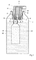
Anhand der Fig. 1, welche einen Längsschnitt durch einen schematisch dargestellten Druckbehälter zeigt, soll der Aufbau des Druckbehälters näher erläutert werden. Da der prinzipielle Aufbau und die Wirkungsweise derartiger Druckbehälter, beispielsweise aus der EP-0 111 089, bekannt ist, wird nachfolgend nur auf die im Zusammenhang mit der vorliegenden Erfindung wesentlichen Merkmale eingegangen.1, which shows a longitudinal section through a schematically Pressure vessel shows, the structure of the pressure vessel should be explained in more detail. There the basic structure and mode of operation of such pressure vessels, for example from EP-0 111 089, is known in the following only to the context essential features of the present invention.
Der Druckbehälter weist ein Metallgehäuse 1 auf, das in ihrem Innern eine erste
Kammer bildet, in der eine flüssige oder halbflüssige Komponente K1 aufgenommen
ist. In das Metallgehäuse 1 ist von oben ein Einsatz 2 eingesetzt, an dem eine gesamthaft
mit 11 bezeichnete Abgabeeinrichtung abgestützt ist. Diese Abgabeeinrichtung
11 umfasst eine Ventilplatte 3, die am Einsatz 2 fixiert ist. Auf der Unterseite
des Einsatzes 2 ist ein zweiter, innerer Metallbehälter 10 befestigt, in dem eine
zweite flüssige oder halbflüssige Komponente K2 aufgenommen ist. Zur Abdichtung
zwischen der Ventilplatte 3 und dem Einsatz 2 ist entweder ein durch einen Spannring
belasteter O-Ring vorgesehen oder der Einsatz 2 ist zur Verbesserung der Abdichtung
zwischen der Ventilplatte 3 und dem Einsatz 2 mit einem Haftvermittler beschichtet.
Die nähere Ausgestaltung dieser Dichtungsanordnung zusammen mit deren
Fixierung wird anschliessend anhand der Figur 2 noch näher erläutert, währenddem
auf das Vorsehen eines Haftvermittlers anhand der Fig. 3 eingegangen wird.
Die Ventilplatte 3 ist mit zwei Durchgangsbohrungen 6, 7 versehen, in die je ein Abgabeventil
8, 9 eingesetzt ist. Die Abgabeventile 8, 9 sind in Längsrichtung elastisch
und einstückig ausgebildet. Zum Öffnen der Abgabeventile 8, 9 ist ein Betätigungslement
12 vorgesehen, welches auf der Unterseite mit zwei rohrartigen
Stutzen 14, 15 versehen ist, die bis zum Boden von in die Abgabeventile 8, 9 eingelassenen
Bohrungen reichen. Durch Drücken des Betätigungslements 12 werden
die Dichtflächen der Abgabeventile 8, 9 in bekannter Weise von den Durchgangsbohrungen
6, 7 abgehoben und die in den beiden Behältern 1, 10 aufgenommenen
Komponenten K1, K2 können über die Auslasskanäle 16, 17 austreten. Die Ventilplatte
3 weist auf ihrer Unterseite einen im wesentlichen hohlzylindrisch ausgebildeten
Fortsatz 18 auf, an dem der innere Behälter 10 befestigt ist. Der Einsatz 2 ist
auf der Oberseite durch Bördelung 19 luftdicht mit dem Metallgehäuse 1 verbunden.
Die Ventilplatte 3 besteht aus einem nicht adhäsiven Kunststoff, vorzugsweise aus
einem Polyolefin wie beispielsweise Polypropylen, oder einem halogenierten Polyolefin.
Unter ![]()
![]()
In der Fig. 2 ist der Einsatz 2 zusammen mit der Ventilplatte 3 und dem Betätigungslement
12 in einer vergrösserten Ansicht dargestellt. Der kreisrund ausgebildete
Einsatz 2 weist auf seiner Unterseite einen im Querschnitt gesehen im wesentlichen
U-förmig ausgebildeten Rand 20 auf Der innere, freie Schenkel 21 des Rands
20 ist derart in die Ventilplatte 3 eingebettet, dass ein Hohlraum 22 zwischen der
Ventilplatte 3 und dem Einsatz 2 entsteht. In diesen Hohlraum 22 ist ein O-Ring 4
eingesetzt, der von einem ringförmig ausgebildeten Spannring 5 belastet ist. Der
Spannring 5 wird durch eine Mehrzahl von Ausbuchtungen 24 im Einsatz 2 fixiert.
Diese Ausbuchtungen 24 werden durch plastische Verformung des Einsatzes 2 erzeugt.
Es versteht sich, dass der Spannring 5 während des Anbringens der Ausbuchtungen
24 mit einer bestimmten Kraft vorbelastet ist, so dass der O-Ring 4 eine
ovale Form annimmt und sich dichtend an der Aussenseite der Ventilplatte 3 und an
der Innenseite des Einsatzes 2 anlegt und die Ventilplatte 3 gegenüber dem Innenraum
des Druckbehälters zuverlässig und langzeitstabil abdichtet. Die Breite des
Hohlraums 22 ist vorzugsweise geringfügig grösser als der Durchmesser des O-Rings
4 im unbelasteten Zustand. Dadurch wird das Einbringen des O-Rings 4 in
den Hohlraum 22 erleichtert.2, the
Um eine sichere Abdichtung der Auslasskanäle 16, 17 durch die Abgabeventile 8, 9
zu gewährleisten, sind die Dichtflächen 26, 27 der Abgabeventile 8, 9 mit Silikon beschichtet.
Dadurch können die eingangs erwähnten Nachteile behoben werden, da
sich das relativ weiche Silikon der Oberflächenkontur -Rauhigkeit- der Ventilplatte 3
anpasst. Zudem hat Silikon den Vorteil, dass es nicht adhäsiv ist.In order to securely seal the
Um den inneren Metallbehälter 10 (Fig. 1) sicher dichtend an der Ventilplatte 3 befestigen
zu können, ist der Fortsatz 18 auf der Aussenseite mit einem erhöhten, zylindrisch
verlaufenden Abschnitt 29 versehen, der eine ringförmig verlaufende Nut 30
aufweist, in der ein weiterer O-Ring 31 aufgenommen ist. Der innere Metallbehälter
10 weist einen mit dem zylindrisch verlaufenden Abschnitt 29 korrespondierenden,
hohlzylindrischen Halsabschnitt (nicht dargestellt) auf, an den sich der O-Ring dichtend
anlegt. Zum Befestigen des inneren Metallbehälters ist der Fortsatz mit einem
Aussengewinde 32 versehen, auf das der innere Behälter mit einem korrespondierenden
Innengewinde geschraubt werden kann.Secure it securely to the
Fig. 3 zeigt eine alternative Ausführungsform zu der in Fig. 2 dargestellten, aus einem
O-Ring und einem Spannring 5 bestehenden Abdichtung zwischen Einsatz und
Ventilplatte. Dazu ist der innere, freie Schenkel 21a des Einsatzes 2a mit einem
Haftvermittler 13 beschichtet. Als Haftvermittler 13 wird vorzugsweise eine Polyurethanmasse
verwendet, welche nebst guten haftvermittelnden Eigenschaften auch
dauerlastisch ist. Die Schichdicke des aufgetragenen Haftvermittlers 13 beträgt vorzugsweise
ca. 2 bis 20 Mikrometer. Bei Versuchen hat sich überraschenderweise
gezeigt, dass durch das Aufbringen einer solchen, auf Polyurethan basierenden
Schicht eine zuverlässige, langzeitstabile Abdichtung zwischen Einsatz 2a und Ventilplatte
3a erreicht wird. Dazu tragen gemäss heutigem Kenntnisstand sowohl die
haftvermittelnden wie auch die dauerelastischen Eigenschaften der Polyurethanschicht
bei.Fig. 3 shows an alternative embodiment to that shown in Fig. 2, from one
O-ring and a
Ein gemäss den beiden vorgängigen Ausführungsbeispielen (Fig. 2 und 3) ausgebildeter Druckbehälter ist in Bezug auf die aufzunehmenden Komponenten universell einsetzbar. Zudem wird verhindert, dass sich der Druck im Behälter abbaut, bzw. dass die aufgenommenen Komponenten mit Sauerstoff und/oder Luftfeuchtigkeit in Berührung kommen. Dadurch eignen sich derartige Behälter insbesondere auch für eine langzeitstabile Lagerung der aufgenommenen Komponenten.A trained according to the two previous embodiments (Fig. 2 and 3) Pressure vessel is universal in terms of the components to be accommodated applicable. It also prevents the pressure in the container from reducing or that the components ingested with oxygen and / or humidity Come into contact. As a result, such containers are particularly suitable for long-term stable storage of the recorded components.
Claims (10)
Priority Applications (1)
| Application Number | Priority Date | Filing Date | Title |
|---|---|---|---|
| DE29924538U DE29924538U1 (en) | 1998-11-11 | 1999-10-20 | Pressure vessel for long-term stable storage of two-component products, with valve plate made of non-adhesive polyolefin plastic |
Applications Claiming Priority (2)
| Application Number | Priority Date | Filing Date | Title |
|---|---|---|---|
| DE19851890A DE19851890B4 (en) | 1998-11-11 | 1998-11-11 | pressure vessel |
| DE19851890 | 1998-11-11 |
Publications (3)
| Publication Number | Publication Date |
|---|---|
| EP1000874A2 true EP1000874A2 (en) | 2000-05-17 |
| EP1000874A3 EP1000874A3 (en) | 2000-08-16 |
| EP1000874B1 EP1000874B1 (en) | 2005-12-07 |
Family
ID=7887351
Family Applications (1)
| Application Number | Title | Priority Date | Filing Date |
|---|---|---|---|
| EP99810948A Expired - Lifetime EP1000874B1 (en) | 1998-11-11 | 1999-10-20 | Pressurized container |
Country Status (3)
| Country | Link |
|---|---|
| EP (1) | EP1000874B1 (en) |
| AT (1) | ATE312028T1 (en) |
| DE (2) | DE19851890B4 (en) |
Cited By (1)
| Publication number | Priority date | Publication date | Assignee | Title |
|---|---|---|---|---|
| EP3312107A4 (en) * | 2016-01-18 | 2018-09-05 | Toyo Aerosol Industry Co., Ltd. | Fixing base for aerosol container |
Families Citing this family (1)
| Publication number | Priority date | Publication date | Assignee | Title |
|---|---|---|---|---|
| ES2537151T3 (en) | 2009-12-10 | 2015-06-02 | Neubourg Skin Care Gmbh & Co. Kg | Polymer stabilized foam formulations, emulsifier free |
Citations (1)
| Publication number | Priority date | Publication date | Assignee | Title |
|---|---|---|---|---|
| EP0111089A2 (en) | 1982-11-30 | 1984-06-20 | Ladoco Ag | Pressurised container for gases, liquids, pasty products or the like |
Family Cites Families (1)
| Publication number | Priority date | Publication date | Assignee | Title |
|---|---|---|---|---|
| GB2324121A (en) * | 1997-04-07 | 1998-10-14 | Bespak Plc | Seal arrangements for pressurised dispensing containers |
-
1998
- 1998-11-11 DE DE19851890A patent/DE19851890B4/en not_active Expired - Fee Related
-
1999
- 1999-10-20 EP EP99810948A patent/EP1000874B1/en not_active Expired - Lifetime
- 1999-10-20 DE DE59912892T patent/DE59912892D1/en not_active Expired - Lifetime
- 1999-10-20 AT AT99810948T patent/ATE312028T1/en not_active IP Right Cessation
Patent Citations (1)
| Publication number | Priority date | Publication date | Assignee | Title |
|---|---|---|---|---|
| EP0111089A2 (en) | 1982-11-30 | 1984-06-20 | Ladoco Ag | Pressurised container for gases, liquids, pasty products or the like |
Cited By (2)
| Publication number | Priority date | Publication date | Assignee | Title |
|---|---|---|---|---|
| EP3312107A4 (en) * | 2016-01-18 | 2018-09-05 | Toyo Aerosol Industry Co., Ltd. | Fixing base for aerosol container |
| US10472163B2 (en) | 2016-01-18 | 2019-11-12 | Toyo Aerosol Industry Co., Ltd. | Fixing plate for aerosol container |
Also Published As
| Publication number | Publication date |
|---|---|
| EP1000874B1 (en) | 2005-12-07 |
| DE19851890B4 (en) | 2005-02-10 |
| EP1000874A3 (en) | 2000-08-16 |
| DE59912892D1 (en) | 2006-01-12 |
| ATE312028T1 (en) | 2005-12-15 |
| DE19851890A1 (en) | 2000-05-31 |
Similar Documents
| Publication | Publication Date | Title |
|---|---|---|
| DE102004003439B4 (en) | Paint cup system for a paint spray gun | |
| DE4443287C2 (en) | Valve assembly for a container for dispensing pressurized liquid or foam | |
| EP0482319B1 (en) | Device for dispensing a mixture consisting of at least two components | |
| EP1718415A1 (en) | Fluid reservoir for a paint spray gun | |
| CH638454A5 (en) | MANUALLY OPERATED SPRAY CAN. | |
| DE10014688A1 (en) | Holding member for fastening components to carrier members using through apertures | |
| EP0111089B1 (en) | Pressurised container for gases, liquids, pasty products or the like | |
| CH632464A5 (en) | HAND SPRAYER. | |
| DE19851890B4 (en) | pressure vessel | |
| EP2389519B1 (en) | Mounting system | |
| DE7505779U (en) | Quiver, in particular a cap for a tube pen tip | |
| WO1983003239A1 (en) | Cap intended to be placed on the central outlet opening of a liquid container | |
| EP0322452A1 (en) | Device for evaporating active substances | |
| DE10231274A1 (en) | Plug for car bodywork has shaft which fits through aperture and flange at top with recess on its underside, into which ring of sealant is placed, rim of flange pressing against bodywork when plug is in position | |
| EP3736049B1 (en) | Discharge head and liquid dispenser with a discharge head | |
| EP0991526A1 (en) | Device for placing a liquid on a substrate | |
| DE102015013425A1 (en) | Beverage can with a closing and opening device | |
| WO1996004483A1 (en) | Adhesive-filled cartridge and attachment device with an adhesive-filled cartridge | |
| EP0438688A1 (en) | Shutt-off valve | |
| DE2901239C2 (en) | Container closure | |
| EP0553441B1 (en) | Device for applying a liquid | |
| DE3126508A1 (en) | DISPENSING VALVE FOR DISPENSING PRESSURE LIQUIDS | |
| EP1742850A1 (en) | Oxygen-absorbing closure | |
| EP4124764A1 (en) | Fastener assembly | |
| DE19610184A1 (en) | Valve body on top of spray can |
Legal Events
| Date | Code | Title | Description |
|---|---|---|---|
| PUAI | Public reference made under article 153(3) epc to a published international application that has entered the european phase |
Free format text: ORIGINAL CODE: 0009012 |
|
| AK | Designated contracting states |
Kind code of ref document: A2 Designated state(s): AT CH DE FR GB LI |
|
| AX | Request for extension of the european patent |
Free format text: AL;LT;LV;MK;RO;SI |
|
| PUAL | Search report despatched |
Free format text: ORIGINAL CODE: 0009013 |
|
| AK | Designated contracting states |
Kind code of ref document: A3 Designated state(s): AT BE CH CY DE DK ES FI FR GB GR IE IT LI LU MC NL PT SE |
|
| AX | Request for extension of the european patent |
Free format text: AL;LT;LV;MK;RO;SI |
|
| 17P | Request for examination filed |
Effective date: 20001005 |
|
| AKX | Designation fees paid |
Free format text: AT CH DE FR GB LI |
|
| 17Q | First examination report despatched |
Effective date: 20041004 |
|
| GRAP | Despatch of communication of intention to grant a patent |
Free format text: ORIGINAL CODE: EPIDOSNIGR1 |
|
| RIN1 | Information on inventor provided before grant (corrected) |
Inventor name: DR. ING. ROLAND LECHNER |
|
| GRAS | Grant fee paid |
Free format text: ORIGINAL CODE: EPIDOSNIGR3 |
|
| GRAA | (expected) grant |
Free format text: ORIGINAL CODE: 0009210 |
|
| AK | Designated contracting states |
Kind code of ref document: B1 Designated state(s): AT CH DE FR GB LI |
|
| PG25 | Lapsed in a contracting state [announced via postgrant information from national office to epo] |
Ref country code: GB Free format text: LAPSE BECAUSE OF FAILURE TO SUBMIT A TRANSLATION OF THE DESCRIPTION OR TO PAY THE FEE WITHIN THE PRESCRIBED TIME-LIMIT Effective date: 20051207 |
|
| REG | Reference to a national code |
Ref country code: GB Ref legal event code: FG4D Free format text: NOT ENGLISH |
|
| REG | Reference to a national code |
Ref country code: CH Ref legal event code: EP |
|
| REF | Corresponds to: |
Ref document number: 59912892 Country of ref document: DE Date of ref document: 20060112 Kind code of ref document: P |
|
| GBV | Gb: ep patent (uk) treated as always having been void in accordance with gb section 77(7)/1977 [no translation filed] |
Effective date: 20051207 |
|
| PLBE | No opposition filed within time limit |
Free format text: ORIGINAL CODE: 0009261 |
|
| STAA | Information on the status of an ep patent application or granted ep patent |
Free format text: STATUS: NO OPPOSITION FILED WITHIN TIME LIMIT |
|
| PG25 | Lapsed in a contracting state [announced via postgrant information from national office to epo] |
Ref country code: LI Free format text: LAPSE BECAUSE OF NON-PAYMENT OF DUE FEES Effective date: 20061031 Ref country code: CH Free format text: LAPSE BECAUSE OF NON-PAYMENT OF DUE FEES Effective date: 20061031 |
|
| 26N | No opposition filed |
Effective date: 20060908 |
|
| EN | Fr: translation not filed | ||
| REG | Reference to a national code |
Ref country code: CH Ref legal event code: PL |
|
| PG25 | Lapsed in a contracting state [announced via postgrant information from national office to epo] |
Ref country code: FR Free format text: LAPSE BECAUSE OF FAILURE TO SUBMIT A TRANSLATION OF THE DESCRIPTION OR TO PAY THE FEE WITHIN THE PRESCRIBED TIME-LIMIT Effective date: 20070126 |
|
| PG25 | Lapsed in a contracting state [announced via postgrant information from national office to epo] |
Ref country code: AT Free format text: LAPSE BECAUSE OF NON-PAYMENT OF DUE FEES Effective date: 20061020 |
|
| PG25 | Lapsed in a contracting state [announced via postgrant information from national office to epo] |
Ref country code: FR Free format text: LAPSE BECAUSE OF FAILURE TO SUBMIT A TRANSLATION OF THE DESCRIPTION OR TO PAY THE FEE WITHIN THE PRESCRIBED TIME-LIMIT Effective date: 20051207 |
|
| PGFP | Annual fee paid to national office [announced via postgrant information from national office to epo] |
Ref country code: DE Payment date: 20181023 Year of fee payment: 20 |
|
| REG | Reference to a national code |
Ref country code: DE Ref legal event code: R071 Ref document number: 59912892 Country of ref document: DE |