EP1000858B1 - Method and device for applying and shrinking a packaging hood on an object - Google Patents
Method and device for applying and shrinking a packaging hood on an object Download PDFInfo
- Publication number
- EP1000858B1 EP1000858B1 EP98121032A EP98121032A EP1000858B1 EP 1000858 B1 EP1000858 B1 EP 1000858B1 EP 98121032 A EP98121032 A EP 98121032A EP 98121032 A EP98121032 A EP 98121032A EP 1000858 B1 EP1000858 B1 EP 1000858B1
- Authority
- EP
- European Patent Office
- Prior art keywords
- film hood
- wrapping
- film
- article
- article according
- Prior art date
- Legal status (The legal status is an assumption and is not a legal conclusion. Google has not performed a legal analysis and makes no representation as to the accuracy of the status listed.)
- Expired - Lifetime
Links
Images


Classifications
-
- B—PERFORMING OPERATIONS; TRANSPORTING
- B65—CONVEYING; PACKING; STORING; HANDLING THIN OR FILAMENTARY MATERIAL
- B65B—MACHINES, APPARATUS OR DEVICES FOR, OR METHODS OF, PACKAGING ARTICLES OR MATERIALS; UNPACKING
- B65B9/00—Enclosing successive articles, or quantities of material, e.g. liquids or semiliquids, in flat, folded, or tubular webs of flexible sheet material; Subdividing filled flexible tubes to form packages
- B65B9/10—Enclosing successive articles, or quantities of material, in preformed tubular webs, or in webs formed into tubes around filling nozzles, e.g. extruded tubular webs
- B65B9/13—Enclosing successive articles, or quantities of material, in preformed tubular webs, or in webs formed into tubes around filling nozzles, e.g. extruded tubular webs the preformed tubular webs being supplied in a flattened state
- B65B9/135—Enclosing successive articles, or quantities of material, in preformed tubular webs, or in webs formed into tubes around filling nozzles, e.g. extruded tubular webs the preformed tubular webs being supplied in a flattened state for palletised loads
-
- B—PERFORMING OPERATIONS; TRANSPORTING
- B65—CONVEYING; PACKING; STORING; HANDLING THIN OR FILAMENTARY MATERIAL
- B65B—MACHINES, APPARATUS OR DEVICES FOR, OR METHODS OF, PACKAGING ARTICLES OR MATERIALS; UNPACKING
- B65B53/00—Shrinking wrappers, containers, or container covers during or after packaging
- B65B53/02—Shrinking wrappers, containers, or container covers during or after packaging by heat
- B65B53/06—Shrinking wrappers, containers, or container covers during or after packaging by heat supplied by gases, e.g. hot-air jets
- B65B53/066—Mobile frames, hoods, posts or the like
Definitions
- the invention relates to a method and an apparatus for packaging a Subject according to the preamble of claim 1 or according to the preamble of claim 13.
- Such a method and a corresponding device are used in particular for packing stacks of goods on a Pallet are arranged and should be transported in any form.
- the stack of goods is protected from the weather by the film hood and receives increased stability.
- a film tube is placed in a processing room supplied in the desired length, welded to a film hood and cut off the formed film hood. Then the film hood opened and with grippers of the shrink frame over the object to be packed drawn. In order to shrink the film hood onto the object then the shrink frame, the one the object to be packed in a ring surrounding heater means from the bottom portion of the article moved up again. The heating device is switched on, see above that the film hood with the supply of heat to the object to be packaged is shrunk.
- the film hood is pulled over shrunk over the object to be packed. This will make the the two process steps of covering and shrinking combined in time, so that the cycle times of the process are shortened and the Performance is increased. Furthermore, the suction of air or there is no need to inflate the film hood while shrinking, because the shrinking takes place while the film hood is pulled over the object becomes. This also enables a particularly uniform and reliable Shrinkage of the film material, which prevents wrinkling.
- the film hood is by means of a heating device by supplying heat above a gripping device shrunk the item. This enables an effective and consistent Shrinking process, because when shrinking the heating device in a fixed Distance to the gripping device and the film wall can be positioned.
- Heat is preferably applied to the film hood before it contacts the Has created object so that the pulling of the film hood over the Object runs essentially without contact. This prevents any Damage such as cracks or the like when pulling over the film hood. Furthermore, the Shrink the film hood wrinkle-free onto the object, reducing its mechanical Properties, especially the tear strength improved.
- the heat supply is at Shrinkage of the film hood controllable, so that objects with irregular Surfaces can be shrunk better.
- the distance of the film hood to the heating device changes, so that an individual adjustment of the heat supply is required for certain areas is.
- the film hood is first applied their top side shrunk onto the object and then the heater together with a gripping device that reefs the film hood Condition holds, moved down. This results in a particularly tight fit the film hood on the object.
- a further increase in performance can be achieved if the film hood is opened by a first gripping device and then to a second gripping device is passed.
- the second gripping device can then initiate the shrinking process together with the heater while the First gripping device pick up the subsequent film hood and put it in the reefed Can bring condition.
- the film hood is on the underside of the object sucked inwards and at least partially on the underside of the object shrunk, so that the seat of the film hood is particularly firm becomes.
- the film hood can bottom area to be welded with a bottom film. This allows also achieve sealed packaging of the item.
- the film hood can be shrunk onto the heated one Area to be cooled. This enables a particularly large one Heat supply in a short time, since the excess heat is dissipated quickly can.
- the heater when the film hood is pulled over over the object the heater at a fixed distance above a second movable gripping device for covering the film hood.
- this makes possible a simultaneous covering of the film hood and shrinking it on the object. It can also be reliable and fast Carry out shrinking because the distance between the film hood and the heating device especially for objects with irregular surfaces, relative is even. This enables wrinkle-free shrinking and deployment a resilient shrunk film hood.
- the gripping device for covering the film hood on the shrink frame connectable or connected to this. In both cases, the distance of the Gripping device to the heater on the shrink frame quickly and fix in a simple way.
- the first gripping device has a plurality of suction boxes for opening the film hood, while the second gripping device is connected to the shrink frame can be.
- the shrink frame has In addition to the heating device, a cooling device with which a rapid cooling of the film hood is achieved after shrinking. This enables an intensive heat supply and a shortening of the timeshrinking process.
- a heat shield is provided so that the opening of the film hood can take place in a relatively sheltered cooler room and sticking the following slide can be prevented.
- a stack of goods 1 is on a pallet 2 arranged so that pallet 2 and stack of goods 1 the object to be packed form.
- the pallet 2 is arranged on a vertically movable lifting table 3, which component e.g. a belt conveyor system and which is on a base part 4 is stored.
- the object to be packaged is arranged within a frame 5 which the individual components of the device are at least partially suspended.
- the film to be fed is unwound from a film roll 6 and in shape a film tube 8 via feed rollers 7 to the upper area of the packaging device guided.
- the upper area of the device forms a processing station 9, in which the film tube 8 to a film hood 20 with the desired length is formed.
- the following film tube is used for this 8 opened and gripped by means of a first gripping device 10.
- there gripper fingers 103 are placed in the film tube. Through on the gripping fingers 103 arranged reef rollers 11, the film tube 8 on the gripping fingers 103 funded.
- the film tube 8 When the film tube 8 has reached the desired length, it is cut off by a cutter 12 and by one below it lying welding device 13 welded together so that a film hood 20 is formed.
- the first gripping device consists of four suction boxes 100, which are attached to the respective Grasp the corners of the film tube to open it. On one edge of the Suction box, a gripping device 101 is provided with which the corresponding Foil tube edge can be pinched. Then the four Suction boxes 100 each moved on two parallel axes 102 such that the opened film tube essentially the contour of the object to be packaged Has. A detailed description of the opening system is in DE 43 26 827 to find.
- the first gripping device is preferably corresponding the suction / gripping device disclosed there. However, it is also possible to use other mechanical opening systems.
- the film hood 20 thus formed essentially the contour of the to be packaged Has taken object, it is to a second gripping device to hand over.
- the second gripping device has four grippers 16, which on one Shrink frames 15 are arranged.
- a heat shield 14 is provided which Processing station 9 separates from the shrinking space to the subsequent film hood not to be glued together by rising heat.
- the heat shield 14 can be formed, for example, by horizontally movable metal plates. Alternatively or additionally, a blower can be used to form an air curtain be used.
- the second gripping device is up moved to the first gripping device or the first gripping device downwards moved to the second gripping device, the four grippers 16 in the im in the ineffected state of the film hood 20.
- the first gripping device then moves in and down or folds the gripper arms inside and below to transfer the film hood 20.
- the first gripping device again to the subsequent hose 8 to the next Form a film hood for the next packaging process.
- the film hood 20 on the grippers 16 now moves down until the The top of the film hood 20 is arranged somewhat above the stack of goods. Subsequently becomes a heating device 17 in the form of several arranged in a ring Gas burner 17 or other suitable heating devices, such as electric radiators, Infrared heater and / or the like. Ignited or switched on and one Cooling device arranged above the gas burners 17 or the heating device 18 switched on in the form of a cooling air blower.
- the film hood 20 together with the grippers 16, the shrink frame 15, the heating device 17 and the cooling device 18 moves down.
- the film hood 20 is pulled over the stack of goods 1 practically without contact and at the same time shrunk onto the stack of goods 1 before contacting the stack of goods 1.
- the film hood 20 is folded over and under the lower edge of the stack of goods or the pallet shrunk so that the film hood 20 has a tight fit around the stack of goods 1 and the pallet 2.
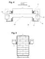
- Bottom film 22 may be provided so that the film hood 20 with the bottom film 22nd is welded. This enables a particularly sealed packaging of the Good stack 1.
- a stack of goods 1 'still to be packed on a pallet becomes the one according to the invention Device transported.
- the shrink frame 15 is still in the lower area of the stack of goods just packed 1.
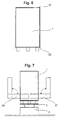
- In the closed position prevents the shrink frame 15 that the still to be packed Item 1 'in the area of the frame 5 and the packaged item 1 can be promoted outside the area of the frame 5. Therefore are the areas of the shrink frame lying in the conveying direction of a conveyor belt 26 15 formed from movable sections 25 which are out of the transport route of the stack of goods 1 and 1 'can be moved.
- the sections 25 of the shrink frame 15 formed by suitable means to pivot the frame 5 in Release direction of the conveyor belt 26. With sections pivoted upwards 25 can still be packed object 1 'during the movement of the shrink frame 15 up to the next film hood in the Area of the frame 5 of the device moved and placed on the lifting table 3 become. Thereafter, the inventive method described above carried out and the subsequent film hood 20 shrunk onto the stack of goods 1 '. As soon as the shrinking process is finished, the packaged goods stack 1 'moved from the area of the frame 5 to the position 1' ', so that again the following stack of goods can be packed. This procedure shortens the cycle times considerably and thus contributes to the increase in performance of the system.
Description
Die Erfindung betrifft ein Verfahren und eine Vorrichtung zum Verpacken eines
Gegenstands nach dem Oberbegriff des Anspruchs 1 bzw. nach dem Oberbegriff
des Anspruchs 13. Ein solches Verfahren und eine entsprechende Vorrichtung
werden insbesondere zum Verpacken von Gutstapeln verwenden, die auf einer
Palette angeordnet sind und in irgendeiner Form transportiert werden sollen.
Durch die Folienhaube wird der Gutstapel vor Witterungseinflüssen geschützt
und erhält eine erhöhte Stabilität.The invention relates to a method and an apparatus for packaging a
Subject according to the preamble of
Bei bekannten Verfahren und Vorrichtungen zum Verpacken von Gegenständen wird in einem ersten Bearbeitungsschritt ein Folienschlauch in einen Bearbeitungsraum in gewünschter Länge zugeführt, zu einer Folienhaube verschweißt und die gebildete Folienhaube abgeschnitten. Anschließend wird die Folienhaube geöffnet und mit Greifern des Schrumpfrahmens über den zu verpackenden Gegenstand gezogen. Um die Folienhaube auf den Gegenstand zu schrumpfen, wird danach der Schrumpfrahmen, der eine den zu verpackenden Gegenstand ringförmig umgebende Heizeinrichtung umfaßt, von dem Bodenbereich des Gegenstands wieder nach oben bewegt. Dabei ist die Heizeinrichtung eingeschaltet, so daß die Folienhaube unter Wärmezufuhr auf den zu verpackenden Gegenstand aufgeschrumpft wird. In known methods and devices for packaging objects In a first processing step, a film tube is placed in a processing room supplied in the desired length, welded to a film hood and cut off the formed film hood. Then the film hood opened and with grippers of the shrink frame over the object to be packed drawn. In order to shrink the film hood onto the object then the shrink frame, the one the object to be packed in a ring surrounding heater means from the bottom portion of the article moved up again. The heating device is switched on, see above that the film hood with the supply of heat to the object to be packaged is shrunk.
Eine entsprechende Vorrichtung, bei der der Schrumpfrahmen mit der Heizeinrichtung korrespondierend zu der Greifeinrichtung beim Überziehen der Folie über den Güterstapel nach unten bewegt wird, ist in der EP 88 424 beschrieben. Doch auch bei dieser Vorrichtung wird die Heizeinrichtung erst dann gestartet, wenn die Folienhaube komplett über den gesamten Güterstapel gezogen ist. Erst dann wird die Heizeinrichtung mit dem Schrumpfrahmen nach oben bewegt, so dass das Aufschrumpfen von unten nach oben erfolgt.A corresponding device in which the shrink frame corresponds to the heating device to the gripping device when the film is pulled over the stack of goods is moved down is described in EP 88 424. But even with this device the heating device only starts when the film hood is completely over the entire Stack of goods is pulled. Only then will the heater with the shrink frame moved upwards, so that the shrinking takes place from bottom to top.
Dieses Verfahren und die entsprechende Vorrichtung sind in ihrer Kapazität recht begrenzt, da die einzelnen Verfahrensschritte nacheinander ausgeführt werden, so daß die Greifeinrichtung die Folienhaube zuerst vollständig über den Gegenstand zieht, bevor der in dem Bodenbereich des Gegenstands befindliche Schrumpfrahmen mit dem Schrumpfvorgang beginnen kann. Erst nach dem Schrumpfvorgang wird der verpackte Gegenstand weiterbefördert und der nächste unverpackte Gegenstand wird in die Vorrichtung bewegt. Die Taktzeit einer solchen bekannten Vorrichtung ist daher relativ lange, was sie im Verhältnis zu der Anzahl der verpackten Gegenstände pro Zeiteinheit relativ teuer macht.This method and the corresponding device are quite limited in their capacity, since the individual process steps are carried out one after the other, so that the gripping device first pull the film hood completely over the object, before the in the Shrink frame located at the bottom of the object with the shrinking process can start. Only after the shrinking process is the packaged item moved on and the next unpacked item is moved into the device. The cycle time Such a known device is therefore relatively long in relation to it the number of packaged items per unit of time makes it relatively expensive.
Ferner ergibt sich keine besondere Schrumpfqualität. Schließlich ist nicht gewährleistet, daß die Folie von bereits geschrumpften Waren des Verpackungsgutes mit der Schrumpffolie verklebt. Um ein solches Verkleben zu verhindern wurden Druckgebläse vorgeschlagen, die die Folienhaube aufblasen, damit diese nicht direkt an dem Gegenstand anliegt. Die Steuerung dieser Gebläse ist jedoch recht aufwendig, und es besteht die Gefahr, daß die Folienhaube durch ein starkes Aufblasen zu nahe zu dem Schrumpfrahmen gelangt und folglich durch ein zu starkes Erhitzen der Folienhaube Löcher in die Folienhaube eingebrannt werden.Furthermore, there is no particular shrink quality. Finally, there is no guarantee that the film of already shrunk goods of the packaged goods with the shrink film bonded. To prevent such sticking, pressure fans have been proposed Inflate the film hood so that it does not lie directly on the object. The control However, this blower is quite expensive and there is a risk that the film hood inflated too close to the shrink frame and consequently holes are burned into the film hood by overheating the film hood.
Es ist daher Aufgabe der vorliegenden Erfindung, ein Verfahren und eine Vorrichtung zum Verpacken eines Gegenstands zu schaffen, bei dem bzw. der die Leistungsfähigkeit erhöht wird, wobei gleichzeitig ein Verkleben der Folienhaube und eine unerwünschte Lochbildung in der Folienhaube und/oder eine unerwünschte Faltenbildung in der Folienhaube vermieden werden. It is therefore an object of the present invention to provide a method and an apparatus for To pack an item that increases performance is, at the same time sticking the film hood and undesirable hole formation in the film hood and / or undesirable wrinkling in the film hood be avoided.
Diese Aufgabe wird mit einem Verfahren gemäß den Merkmalen des Anspruchs 1 und mit
einer Vorrichtung mit den Merkmalen des Anspruchs 13 gelöst. Vorteilhafte Ausgestaltungen
der Erfindung sind in den abhängigen Ansprüchen offenbart. This object is achieved with a method according to the features of
Gemäß dem erfindungsgemäßen Verfahren wird die Folienhaube beim Überziehen über den zu verpackenden Gegenstand aufgeschrumpft. Dadurch werden die beiden Verfahrensschritte des Überziehens und des Schrumpfens zeitlich zusammengefaßt, so daß die Taktzeiten des Verfahrens verkürzt werden und die Leistungsfähigkeit vergrößert wird. Ferner kann auf das Absaugen von Luft oder das Aufblasen der Folienhaube während des Schrumpfens verzichtet werden, da das Schrumpfen stattfindet, während die Folienhaube über den Gegenstand gezogen wird. Dies ermöglicht auch ein besonders gleichmäßiges und zuverlässiges Schrumpfen des Folienmaterials, bei dem eine Faltenbildung verhindert wird.According to the method according to the invention, the film hood is pulled over shrunk over the object to be packed. This will make the the two process steps of covering and shrinking combined in time, so that the cycle times of the process are shortened and the Performance is increased. Furthermore, the suction of air or there is no need to inflate the film hood while shrinking, because the shrinking takes place while the film hood is pulled over the object becomes. This also enables a particularly uniform and reliable Shrinkage of the film material, which prevents wrinkling.
In einer bevorzugten Ausgestaltung der Erfindung wird die Folienhaube mittels einer Heizeinrichtung durch Wärmezufuhr oberhalb einer Greifeinrichtung auf den Gegenstand aufgeschrumpft. Dies ermöglicht einen effektiven und beständigen Schrumpfvorgang, da beim Schrumpfen die Heizeinrichtung in einem festen Abstand zu der Greifeinrichtung und der Folienwand positioniert werden kann.In a preferred embodiment of the invention, the film hood is by means of a heating device by supplying heat above a gripping device shrunk the item. This enables an effective and consistent Shrinking process, because when shrinking the heating device in a fixed Distance to the gripping device and the film wall can be positioned.
Bevorzugt wird die Folienhaube mit Wärme beaufschlagt, bevor sie sich an den Gegenstand angelegt hat, so daß der Überziehvorgang der Folienhaube über den Gegenstand im wesentlichen berührungslos abläuft. Dies verhindert etwaige Schäden, wie Risse o. dgl. beim Überziehen der Folienhaube. Ferner läßt sich die Folienhaube faltenfrei auf den Gegenstand aufschrumpfen, was ihre mechanischen Eigenschaften, insbesondere die Reißfestigkeit verbessert.Heat is preferably applied to the film hood before it contacts the Has created object so that the pulling of the film hood over the Object runs essentially without contact. This prevents any Damage such as cracks or the like when pulling over the film hood. Furthermore, the Shrink the film hood wrinkle-free onto the object, reducing its mechanical Properties, especially the tear strength improved.
In einer bevorzugten Ausgestaltung der Erfindung ist die Wärmezufuhr beim Schrumpfen der Folienhaube steuerbar, so daß Gegenstände mit unregelmäßigen Oberflächen besser geschrumpft werden können. Bei unregelmäßigen Oberflächen verändert sich der Abstand der Folienhaube zu der Heizeinrichtung, so daß eine individuelle Anpassung der Wärmezufuhr für gewisse Bereiche erforderlich ist. In a preferred embodiment of the invention, the heat supply is at Shrinkage of the film hood controllable, so that objects with irregular Surfaces can be shrunk better. For irregular surfaces the distance of the film hood to the heating device changes, so that an individual adjustment of the heat supply is required for certain areas is.
Gemäß einem besonders effektiven Verfahren wird zuerst die Folienhaube an ihrer Oberseite auf den Gegenstand geschrumpft und anschließend die Heizeinrichtung zusammen mit einer Greifeinrichtung, die die Folienhaube in gerefftem Zustand hält, nach unten bewegt. Dadurch ergibt sich ein besonders fester Sitz der Folienhaube auf dem Gegenstand.According to a particularly effective method, the film hood is first applied their top side shrunk onto the object and then the heater together with a gripping device that reefs the film hood Condition holds, moved down. This results in a particularly tight fit the film hood on the object.
Eine weitere Steigerung der Leistungsfähigkeit läßt sich erreichen, wenn die Folienhaube durch eine erste Greifeinrichtung geöffnet wird und dann an eine zweite Greifeinrichtung übergeben wird. Die zweite Greifeinrichtung kann dann zusammen mit der Heizeinrichtung den Schrumpfvorgang einleiten, während die erste Greifeinrichtung die nachfolgende Folienhaube aufnehmen und in den gerefften Zustand bringen kann.A further increase in performance can be achieved if the film hood is opened by a first gripping device and then to a second gripping device is passed. The second gripping device can then initiate the shrinking process together with the heater while the First gripping device pick up the subsequent film hood and put it in the reefed Can bring condition.
In einer bevorzugten Ausführungsform wird die Folienhaube an der Unterseite des Gegenstands nach innen gesaugt und zumindest teilweise an der Unterseite des Gegenstands aufgeschrumpft, so daß der Sitz der Folienhaube besonders fest wird. Für eine weitere Erhöhung der Stabilität kann die Folienhaube in ihrem unteren Bereich mit einer Bodenfolie verschweißt werden. Dadurch läßt sich auch eine abgedichtete Verpackung des Gegenstands erreichen. Um die Taktzeiten möglichst kurz zu gestalten, kann die Folienhaube in dem erhitzten aufgeschrumpften Bereich gekühlt werden. Dies ermöglicht eine besonders große Wärmezufuhr in kurzer Zeit, da die überschüssige Wärme schnell abgeführt werden kann.In a preferred embodiment, the film hood is on the underside of the object sucked inwards and at least partially on the underside of the object shrunk, so that the seat of the film hood is particularly firm becomes. For a further increase in stability, the film hood can bottom area to be welded with a bottom film. This allows also achieve sealed packaging of the item. At the cycle times To make it as short as possible, the film hood can be shrunk onto the heated one Area to be cooled. This enables a particularly large one Heat supply in a short time, since the excess heat is dissipated quickly can.
Gemäß der erfindungsgemäßen Vorrichtung ist beim Überziehen der Folienhaube über den Gegenstand die Heizeinrichtung in einem festen Abstand oberhalb einer zweiten bewegbaren Greifeinrichtung zum Überziehen der Folienhaube angeordnet. Dies ermöglicht ein gleichzeitiges Überziehen der Folienhaube und Schrumpfen derselben auf den Gegenstand. Ferner läßt sich ein zuverlässiges und schnelles Schrumpfen durchführen, da der Abstand der Folienhaube zu der Heizeinrichtung, insbesondere bei Gegenständen mit unregelmäßigen Oberflächen, relativ gleichmäßig ist. Dies ermöglicht ein faltenfreies Schrumpfen und die Bereitstellung einer belastbaren geschrumpften Folienhaube.According to the device according to the invention when the film hood is pulled over over the object the heater at a fixed distance above a second movable gripping device for covering the film hood. this makes possible a simultaneous covering of the film hood and shrinking it on the object. It can also be reliable and fast Carry out shrinking because the distance between the film hood and the heating device especially for objects with irregular surfaces, relative is even. This enables wrinkle-free shrinking and deployment a resilient shrunk film hood.
In einer bevorzugten Ausführungsform der erfindungsgemäßen Vorrichtung ist die Greifeinrichtung zum Überziehen der Folienhaube an den Schrumpfrahmen koppelbar oder mit diesem verbunden. In beiden Fällen läßt sich der Abstand der Greifeinrichtung zu der Heizeinrichtung an dem Schrumpfrahmen schnell und auf einfache Weise fixieren.In a preferred embodiment of the device according to the invention the gripping device for covering the film hood on the shrink frame connectable or connected to this. In both cases, the distance of the Gripping device to the heater on the shrink frame quickly and fix in a simple way.
Vorzugsweise kann die erste Greifeinrichtung mehrere Saugkästen zum Öffnen der Folienhaube aufweisen, während die zweite Greifeinrichtung mit dem Schrumpfrahmen verbunden sein kann.Preferably can the the first gripping device has a plurality of suction boxes for opening the film hood, while the second gripping device is connected to the shrink frame can be.
Gemäß einer bevorzugten Ausführungsform der Erfindung besitzt der Schrumpfrahmen neben der Heizeinrichtung auch eine Kühlvorrichtung, mit der ein schnelles Abkühlen der Folienhaube nach dem Schrumpfen erreicht wird. Dies ermöglicht eine intensive Wärmezufuhr und eine zeitliche Verkürzung des Schrumpfvorgangs.According to a preferred embodiment of the invention, the shrink frame has In addition to the heating device, a cooling device with which a rapid cooling of the film hood is achieved after shrinking. This enables an intensive heat supply and a shortening of the time Shrinking process.
Vorzugsweise ist zwischen der ersten Greifeinrichtung und der zweiten Greifeinrichtung eine Wärmeabschirmung vorgesehen, so daß das Öffnen der Folienhaube in einem relativ geschützten kühleren Raum stattfinden kann und Verklebungen der nachfolgenden Folie verhindert werden können.Is preferably between the first gripping device and the second gripping device a heat shield is provided so that the opening of the film hood can take place in a relatively sheltered cooler room and sticking the following slide can be prevented.
Die Erfindung wird nachfolgend anhand eines Ausführungsbeispiels mit Bezug auf die beigefügten Zeichnungen beschrieben. Es zeigen:
- Fig. 1
- eine schematische Ansicht einer erfindungsgemäßen Vorrichtung;
- Fig. 2
- eine vergrößerte Darstellung der Greifeinrichtung zum Öffnen der Folienhaube;
- Fig. 3
- eine vergrößerte Darstellung eines Ausschnitts der ersten Greifeinrichtung zum Öffnen der Folienhaube;
- Fig. 4
- eine Darstellung der erfindungsgemäßen Vorrichtung, bei der die Folienhaube in verschiedenen Verfahrenszuständen gezeigt ist;
- Fig. 5
- eine schematische Darstellung des Schrumpfvorgangs;
- Fig. 6
- eine Ansicht des fertig verpackten Gegenstands;
- Fig. 7
- eine ausschnittsweise Ansicht des zu verpackenden Gegenstands auf einem Hubtisch, und
- Fig. 8
- eine schematische Darstellung des Fördervorgangs durch die erfindungsgemäße Vorrichtung.
- Fig. 1
- a schematic view of a device according to the invention;
- Fig. 2
- an enlarged view of the gripping device for opening the film hood;
- Fig. 3
- an enlarged view of a section of the first gripping device for opening the film hood;
- Fig. 4
- a representation of the device according to the invention, in which the film hood is shown in different process states;
- Fig. 5
- a schematic representation of the shrinking process;
- Fig. 6
- a view of the packaged item;
- Fig. 7
- a partial view of the object to be packed on a lifting table, and
- Fig. 8
- a schematic representation of the conveying process by the device according to the invention.
Bei der erfindungsgemäßen Vorrichtung ist ein Gutstapel 1 auf einer Palette 2
angeordnet, so daß Palette 2 und Gutstapel 1 den zu verpackenden Gegenstand
bilden. Die Palette 2 ist auf einem vertikal bewegbaren Hubtisch 3 angeordnet,
welcher Bestandteil z.B. einer Bandförderanlage ist und der auf einem Basisteil 4
gelagert ist.In the device according to the invention, a stack of
Der zu verpackende Gegenstand ist innerhalb eines Gestells 5 angeordnet, an
dem die einzelnen Bauteile der Vorrichtung zumindest teilweise aufgehängt sind.
Die zuzuführende Folie wird von einem Folienwickel 6 abgewickelt und in Form
eines Folienschlauchs 8 über Zuführrollen 7 zu dem oberen Bereich der Verpakkungsvorrichtung
geführt. Der obere Bereich der Vorrichtung bildet eine Bearbeitungsstation
9, in der der Folienschlauch 8 zu einer Folienhaube 20 mit der
gewünschten Länge ausgebildet wird. Hierfür wird der nachfolgende Folienschlauch
8 mittels einer ersten Greifeinrichtung 10 geöffnet und gegriffen. Dabei
werden Greiffinger 103 in den Folienschlauch gebracht. Durch an den Greiffingern
103 angeordnete Reffrollen 11 wird der Folienschlauch 8 auf die Greiffinger
103 gefördert. Wenn der Folienschlauch 8 die gewünschte Länge erreicht hat,
wird er durch eine Schneideinrichtung 12 abgeschnitten und durch eine darunter
liegende Schweißvorrichtung 13 zusammengeschweißt, so daß eine Folienhaube
20 gebildet wird.The object to be packaged is arranged within a
Die erste Greifeinrichtung besteht aus vier Saugkästen 100, die an den jeweiligen
Ecken des Folienschlauchs angreifen, um diesen zu öffnen. An einer Kante des
Saugkastens ist eine Greifeinrichtung 101 vorgesehen, mit der die entsprechende
Folienschlauchkante eingeklemmt werden kann. Anschließend werden die vier
Saugkästen 100 jeweils auf zwei parallelen Achsen 102 derart bewegt, daß der
geöffnete Folienschlauch im wesentlichen die Kontur des zu verpackenden Gegenstands
hat. Eine detaillierte Beschreibung des Öffnungssystems ist in der DE
43 26 827 zu finden. Die erste Greifeinrichtung ist vorzugsweise entsprechend
der dort offenbarten Saug-/Greifeinrichtung ausgebildet. Es ist jedoch auch möglich,
andere mechanische Öffnungssysteme zu verwenden.The first gripping device consists of four
Wenn die so gebildete Folienhaube 20 im wesentlichen die Kontur des zu verpakkenden
Gegenstands eingenommen hat, wird sie an eine zweite Greifeinrichtung
übergeben. Die zweite Greifeinrichtung besitzt vier Greifer 16, die an einem
Schrumpfrahmen 15 angeordnet sind. Zwischen der ersten Greifeinrichtung und
der zweiten Greifeinrichtung ist eine Wärmeabschirmung 14 vorgesehen, die die
Bearbeitungsstation 9 von dem Schrumpfraum trennt, um die nachfolgende Folienhaube
nicht durch aufsteigende Wärme zu verkleben. Die Wärmeabschirmung
14 kann beispielsweise durch horizontal bewegbare Metallplatten gebildet werden.
Alternativ oder zusätzlich kann ein Gebläse zur Ausbildung eines Luftvorhangs
eingesetzt werden.If the
Für die Übergabe der Folienhaube 20 wird die zweite Greifeinrichtung nach oben
zu der ersten Greifeinrichtung bewegt oder die erste Greifeinrichtung nach unten
zu der zweiten Greifeinrichtung bewegt, wobei die vier Greifer 16 in die im
gerefften Zustand befindliche Folienhaube 20 bewegt werden. Die erste Greifeinrichtung
bewegt sich dann nach innen und unten oder klappt die Greifarme nach
innen und unten, um die Folienhaube 20 zu übergeben.For the transfer of the
Sobald die Greifer 16 die Folienhaube 20 übernommen haben, bewegt sich die
erste Greifeinrichtung wieder zu dem nachfolgenden Schlauch 8, um die nächste
Folienhaube für den nächsten Verpackungsvorgang zu bilden.As soon as the
Die Folienhaube 20 auf den Greifern 16 bewegt sich nun nach unten, bis die
Oberseite der Folienhaube 20 etwas oberhalb des Gutstapels angeordnet ist. Anschließend
wird eine Heizeinrichtung 17 in Form mehrerer ringförmig angeordneter
Gasbrenner 17 oder sonstiger geeigneter Heizeinrichtungen, wie Elektroheizkörper,
Infrarotstrahler und/oder dgl. gezündet bzw. angeschaltet und eine
über den Gasbrennern 17 bzw. der Heizeinrichtung angeordnete Kühleinrichtung
18 in Form eines Kühlluftgebläses angeschaltet. Gleichzeitig wird die Folienhaube
20 zusammen mit den Greifern 16, dem Schrumpfrahmen 15, der Heizeinrichtung
17 und der Kühleinrichtung 18 nach unten bewegt. Bei der Bewegung
wird die Folienhaube auf den Gutstapel 1 geschrumpft, wobei durch das
gleichmäßige Schrumpfen der Folienhaube eine Faltenbildung vermieden wird.
Die Folienhaube 20 wird praktisch berührungslos über den Gutstapel 1 gezogen
und gleichzeitig vor dem Anliegen an dem Gutstapel 1 auf den Gutstapel 1 aufgeschrumpft. The
Im unteren Bereich des Gutstapels wird die Folienhaube 20 umgelegt und unter
die untere Kante des Gutstapels oder der Palette geschrumpft, so daß die Folienhaube
20 einen festen Sitz um den Gutstapel 1 und die Palette 2 hat.In the lower area of the stack of goods, the
Wie in Fig. 6 gezeigt ist, kann zwischen der Palette 2 und dem Gutstapel 1 eine
Bodenfolie 22 vorgesehen sein, so daß die Folienhaube 20 mit der Bodenfolie 22
verschweißt wird. Dies ermöglicht eine besonders abgedichtete Verpackung des
Gutstapels 1.As shown in Fig. 6, one can between the
Nachfolgend wird der Verpackungsprozeß mit Bezug auf die Fig. 7 und 8 erläutert.
Ein noch zu verpackender Gutstapel 1' auf einer Palette wird zu der erfindungsgemäßen
Vorrichtung befördert. Der Schrumpfrahmen 15 befindet isch
noch in dem unteren Bereich des gerade eben verpackten Gutstapels 1. In der
geschlossenen Stellung verhindert der Schrumpfrahmen 15, daß der noch zu verpackende
Gegenstand 1' in den Bereich des Gestells 5 und der verpackte Gegenstand
1 außerhalb des Bereichs des Gestells 5 gefördert werden kann. Daher sind
die in Förderrichtung eines Förderbandes 26 liegende Bereiche des Schrumpfrahmens
15 aus bewegbaren Abschnitten 25 gebildet, die aus dem Transportweg
des Gutstapels 1 und 1' bewegt werden können.The packaging process is explained below with reference to FIGS. 7 and 8.
A stack of goods 1 'still to be packed on a pallet becomes the one according to the invention
Device transported. The
Wie in Fig. 7 zu erkennen ist, sind die Abschnitte 25 des Schrumpfrahmens 15
durch geeignete Einrichtungen schwenkbar ausgebildet, um das Gestell 5 in
Richtung des Förderbandes 26 freizugeben. Bei nach oben geschwenkten Abschnitten
25 kann der noch zu verpackende Gegenstand 1' während der Bewegung
des Schrumpfrahmens 15 nach oben zu der nächsten Folienhaube in den
Bereich des Gestells 5 der Vorrichtung bewegt und auf dem Hubtisch 3 abgesetzt
werden. Danach wird das oben beschriebene erfindungsgemäße Verfahren
durchgeführt und die nachfolgende Folienhaube 20 auf den Gutstapel 1' geschrumpft.
Sobald der Schrumpfvorgang beendet ist, wird der verpackte Gutstapel
1' aus dem Bereich des Gestells 5 zu der Position 1'' bewegt, so daß wieder
der nachfolgende Gutstapel verpackt werden kann. Dieses Verfahren verkürzt
die Taktzeiten erheblich und trägt somit zur Leistungssteigerung der Anlage bei.As can be seen in FIG. 7, the
Claims (21)
- Method of wrapping an article, especially a palleted stack of goods (1), with a shrinkable film (8, 20), wherein a film hood (20) is formed from a film tube and the film hood (20) is grasped, opened and gathered together by a gripping device (10, 11),
characterised in that
the film hood (20) is drawn over the article being wrapped and at the same time the film hood (20) is shrunk onto the article. - Method of wrapping an article according to claim 1, characterised in that the film hood (20) is shrunk onto the article by means of a heating device (17) by supplying heat above a gripping device (16).
- Method of wrapping an article according to claim 1 or 2, characterised in that the film hood (20) is acted upon by heat before it has made contact with the article.
- Method of wrapping an article according to any one of claims 1 to 3, characterised in that the supply of heat during shrinking of the film hood (20) is controllable.
- Method of wrapping an article according to any one of claims 1 to 4, characterised in that the film hood (20) is opened by a first gripping device (10, 11) and is then transferred to a second gripping device (16).
- Method of wrapping an article according to claim 5, characterised in that using the heating device (17) first the upper side of the film hood (20) is shrunk onto the article and then the heating device (17) and the second gripping device (16), which holds the film hood (20) in the reefed state, are moved downwards together.
- Method of wrapping an article according to any one of claims 1 to 6, characterised in that the film hood (20) is sucked inwards at the underside of the article and is shrunk on over at least part of the underside of the article.
- Method of wrapping an article according to any one of claims 1 to 7, characterised in that the film hood (20) is at its lower region welded to a bottom film (22).
- Method of wrapping an article according to any one of claims 1 to 8, characterised in that the film hood (20) is cooled in the heated shrunk-on region.
- Method of wrapping an article according to any one of claims 1 to 9, characterised in that when the film hood (20) is being applied, the second gripping device (16) and the heating device (17) are moved together.
- Method of wrapping an article according to any one of claims 1 to 9, characterised in that for application of the film hood (20) the article is moved into the film hood.
- Method of wrapping an article according to any one of the preceding claims, characterised in that the shrink frame (15) has movable parts (25) which, after the shrinking operation, are moved out of the transport region of the wrapped stack of goods (1) and a subsequent stack of goods (1'), and the stacks of goods (1, 1') are moved further during the movement of the shrink frame (15) upwards.
- Device for wrapping an article, especially a stack of goods (1) arranged on a pallet (2), with a shrinkable film (8, 20), having:characterised in thata feed device (6, 7) for feeding a film tube (8) to a processing station (10, 11, 12, 13);a first processing station (10, 11, 12, 13) for forming a film hood (20);a first gripping device (10, 11) for opening the film hood (20);a movable shrink frame (15) having a heating device (17) for shrinking the film hood (20) onto the article being wrapped,
for drawing the film hood (20) over the article there is provided a second movable gripping device (16) which is coupled to the shrink frame (15), so that the heating device (17), which is arranged and operable above the second gripping device (16), shrinks the film during application. - Device for wrapping an article according to claim 13, characterised in that the second gripping device (16), for application of the film hood (20), is couplable to the shrink frame (15).
- Device for wrapping an article according to claim 13 or 14, characterised in that the second gripping device (16), for application of the film hood (20), is connected to the shrink frame (15).
- Device for wrapping an article according to any one of claims 13 to 15, characterised in that the first gripping device (10, 11), for opening the film hood (20), comprises four gripping arms (103), which are arranged in a rectangle, and four suction boxes (100).
- Device for wrapping an article according to any one of claims 13 to 16, characterised in that the second gripping device (16), for application of the film hood (20), has four gripping fingers (16) arranged in a rectangle, which gripping fingers are movable into the opened film hood (20) in order to take over the reefed film hood.
- Device for wrapping an article according to any one of claims 13 to 17, characterised in that the shrink frame (15) has, above the heating device (17), a cooling device (18) for cooling the film hood (20).
- Device for wrapping an article according to any one of claims 13 to 18, characterised in that the article being wrapped is arranged on a lifting platform (3), in the region of which there is provided an extractor fan.
- Device for wrapping an article according to any one of claims 13 to 19, characterised in that the shrink frame (15) has at least one movable part (25) lying in the direction of transport of the stack of goods (1).
- Device for wrapping an article according to claim 20, characterised in that the shrink frame (15) has on each of two opposite sides two movable parts (25) which are pivotable away out of the transport path of the stack of goods (1, 1').
Priority Applications (4)
| Application Number | Priority Date | Filing Date | Title |
|---|---|---|---|
| ES98121032T ES2222546T3 (en) | 1998-11-05 | 1998-11-05 | PROCEDURE AND DEVICE FOR THE SETTING AND CONTRACTION OF A PACKING CAPERUZA ON AN OBJECT. |
| EP98121032A EP1000858B1 (en) | 1998-11-05 | 1998-11-05 | Method and device for applying and shrinking a packaging hood on an object |
| DE59811838T DE59811838D1 (en) | 1998-11-05 | 1998-11-05 | Method and device for attaching and shrinking a packaging hood onto an object |
| US09/432,527 US6298636B1 (en) | 1998-11-05 | 1999-11-03 | Method and apparatus for packaging an object |
Applications Claiming Priority (1)
| Application Number | Priority Date | Filing Date | Title |
|---|---|---|---|
| EP98121032A EP1000858B1 (en) | 1998-11-05 | 1998-11-05 | Method and device for applying and shrinking a packaging hood on an object |
Publications (2)
| Publication Number | Publication Date |
|---|---|
| EP1000858A1 EP1000858A1 (en) | 2000-05-17 |
| EP1000858B1 true EP1000858B1 (en) | 2004-08-18 |
Family
ID=8232925
Family Applications (1)
| Application Number | Title | Priority Date | Filing Date |
|---|---|---|---|
| EP98121032A Expired - Lifetime EP1000858B1 (en) | 1998-11-05 | 1998-11-05 | Method and device for applying and shrinking a packaging hood on an object |
Country Status (4)
| Country | Link |
|---|---|
| US (1) | US6298636B1 (en) |
| EP (1) | EP1000858B1 (en) |
| DE (1) | DE59811838D1 (en) |
| ES (1) | ES2222546T3 (en) |
Cited By (1)
| Publication number | Priority date | Publication date | Assignee | Title |
|---|---|---|---|---|
| EP1843066A1 (en) | 2006-03-18 | 2007-10-10 | PFEIFFER CHEMIE-ARMATURENBAU GmbH | Mechanism for the dosed filling of a medium |
Families Citing this family (24)
| Publication number | Priority date | Publication date | Assignee | Title |
|---|---|---|---|---|
| EP1059233A1 (en) * | 1999-04-16 | 2000-12-13 | Kl- Lachenmeier A/S | Method and device for packaging objects in a film-hood |
| DE10020856B9 (en) * | 2000-04-28 | 2007-10-04 | MSK-Verpackungs-Systeme Gesellschaft mit beschränkter Haftung | Device for wrapping piece or packaged goods |
| DE10103261A1 (en) * | 2001-01-25 | 2002-08-14 | Msk Verpackung Syst Gmbh | Method of covering a flat hose |
| EP1636094B1 (en) * | 2003-06-20 | 2008-08-06 | Seelen A/S | A method and a system for packaging objects in tubular film |
| WO2007071063A1 (en) * | 2005-12-23 | 2007-06-28 | Les Plastiques Balcan Limitée | Apparatus for bagging material |
| CA2723059A1 (en) * | 2006-03-22 | 2007-09-22 | Jacques Dussault | Apparatus and method for bagging material |
| US7861500B2 (en) * | 2008-07-14 | 2011-01-04 | Bradley Arthur Bennett | Automatic cart bagger |
| DE202010001587U1 (en) * | 2010-01-29 | 2010-04-22 | Msk - Verpackungs-Systeme Gmbh | Device for wrapping a stack of goods with a film |
| US9149122B1 (en) | 2010-11-04 | 2015-10-06 | J Squared, Inc. | Chair palletizing method |
| DE102011000205B4 (en) | 2011-01-18 | 2014-07-17 | Illinois Tool Works Inc. | Apparatus and method for reefing a tubular film section |
| DE102011075451B4 (en) * | 2011-05-06 | 2014-05-08 | Illinois Tool Works Inc. | Method and device for impinging a tubular film section on the refining fingers of a packaging installation |
| FI124180B (en) | 2011-09-30 | 2014-04-15 | Illinois Tool Works | Method of bringing a winding machine into a transport position and winding machine |
| KR20130089035A (en) * | 2012-02-01 | 2013-08-09 | 삼성전자주식회사 | Shrink film packing system |
| FI125661B (en) | 2012-09-07 | 2015-12-31 | Signode Int Ip Holdings Llc | Method and apparatus for attaching corner guard to a load |
| DK2767479T3 (en) | 2013-02-19 | 2016-08-01 | Erin Intellectual Property Ltd | An apparatus for wrapping an article with a tubular film |
| FI125411B (en) | 2013-10-31 | 2015-10-15 | Signode Internat Ip Holdings Llc | Method and Attachment Device for Attaching the End of a Wrapping Film Web to a Wrapping Machine, and a Wrapping Machine |
| DE102014106365B4 (en) | 2014-05-07 | 2017-06-14 | Lachenmeier Aps | Packaging process for packaging a good |
| DE202014102841U1 (en) * | 2014-06-23 | 2015-09-24 | MSK-Verpackungs-Systeme Gesellschaft mit beschränkter Haftung | Opening device for opening a gusseted in a flat folded state, in particular of a hose supply, gusseted hose |
| DE102015101489A1 (en) * | 2015-02-02 | 2016-08-04 | Signode Industrial Group Llc | Packaging device and method of operating the same |
| GB201506182D0 (en) * | 2015-04-13 | 2015-05-27 | Composite Technology & Applic Ltd | Bagging apparatus |
| EP3147226B1 (en) * | 2015-09-23 | 2018-07-04 | MSK - Verpackungs-Systeme GmbH | Method for creating at least one clearance in a sheath composed of shrink film, securing a stack of articles on a pallet, and moulding device for carrying out said method |
| DE102016212436B4 (en) * | 2016-07-07 | 2018-07-26 | Signode Industrial Group Llc | Packaging process and hood stretcher |
| DK3381816T3 (en) * | 2017-03-28 | 2021-05-10 | Msk Verpackung Syst Gmbh | Method for establishing at least one free space in a cladding consisting of stretch foil and securing a stack of goods placed on a pallet, as well as molding device for carrying out the method |
| CN115402590A (en) * | 2022-07-29 | 2022-11-29 | 江苏兴业汽车饰件有限公司 | Automobile part surface film sealing equipment with size scanning and calculating functions |
Family Cites Families (8)
| Publication number | Priority date | Publication date | Assignee | Title |
|---|---|---|---|---|
| FR2473985A1 (en) * | 1980-01-17 | 1981-07-24 | Thimon | MACHINE FOR PACKING A LOAD IN A SHEET STRING IN A FLEXIBLE MATERIAL |
| DE3208544A1 (en) * | 1982-03-10 | 1983-09-15 | INDAG Gesellschaft für Industriebedarf mbH, 6900 Heidelberg | METHOD AND DEVICE FOR APPLYING SHRINK FILMS ON PALLETED GOETER STACKS |
| US4563689A (en) * | 1983-02-05 | 1986-01-07 | Konishiroku Photo Industry Co., Ltd. | Method for ink-jet recording and apparatus therefor |
| DE8513892U1 (en) * | 1985-05-10 | 1985-09-05 | MSK - Verpackungs-Systeme GmbH, 4190 Kleve | Device for covering and shrinking stacks of goods with shrink hoods |
| DE3621297A1 (en) * | 1986-06-25 | 1988-01-14 | Moellers Maschf Gmbh | DEVICE FOR PULLING ON AND SHRINKING A SHRINK FILM HOOD OVER OR ON A STACK. |
| ATE67727T1 (en) * | 1987-03-26 | 1991-10-15 | Vfi Verpackungstech | METHOD AND DEVICE FOR SHRINKING A FILM HOOD ON A PALLETIZED STACK OF GOODS. |
| EP0378730B1 (en) * | 1989-01-20 | 1993-07-14 | Kurt Lachenmeier A/S | Apparatus for packaging articles using a tubular web of plastic material |
| FR2723564B1 (en) * | 1994-08-12 | 1996-09-20 | Newtec Int | PROCESS AND DEVICE FOR OVERPACKING, BY THERMO-RETRACTION, OF A PALLETIZED LOAD |
-
1998
- 1998-11-05 DE DE59811838T patent/DE59811838D1/en not_active Expired - Fee Related
- 1998-11-05 EP EP98121032A patent/EP1000858B1/en not_active Expired - Lifetime
- 1998-11-05 ES ES98121032T patent/ES2222546T3/en not_active Expired - Lifetime
-
1999
- 1999-11-03 US US09/432,527 patent/US6298636B1/en not_active Expired - Fee Related
Cited By (1)
| Publication number | Priority date | Publication date | Assignee | Title |
|---|---|---|---|---|
| EP1843066A1 (en) | 2006-03-18 | 2007-10-10 | PFEIFFER CHEMIE-ARMATURENBAU GmbH | Mechanism for the dosed filling of a medium |
Also Published As
| Publication number | Publication date |
|---|---|
| US6298636B1 (en) | 2001-10-09 |
| DE59811838D1 (en) | 2004-09-23 |
| ES2222546T3 (en) | 2005-02-01 |
| EP1000858A1 (en) | 2000-05-17 |
Similar Documents
| Publication | Publication Date | Title |
|---|---|---|
| EP1000858B1 (en) | Method and device for applying and shrinking a packaging hood on an object | |
| DE4103384C2 (en) | Device for covering stretch film hoods over a stack of goods | |
| EP1940686B1 (en) | Method and device for shrinking a heat shrink film placed around a stack of items, in particular a palleted stack of items | |
| DE3242677C2 (en) | ||
| DE102016125588A1 (en) | Packaging installation and method for producing a packaging unit, as well as a packaging unit consisting of packaging coats and outer packaging | |
| EP1963187B1 (en) | Hood packaging installation with device for producing side folds | |
| DE3120215A1 (en) | "PLANT FOR MANUFACTURING PALLETLESS, FILM-SHRINKED PIECE STACK, IN PARTICULAR BAG STACK" | |
| EP3672875B1 (en) | Packaging system and method for packaging objects | |
| DE60024523T2 (en) | Method and apparatus for making and applying a flexible heat-shrinkable hood to a palletized load | |
| DE2057998A1 (en) | Method and device for wrapping an object with side, front and top surfaces in a packaging material | |
| DE2729964B2 (en) | Device for automatically wrapping a bowl filled with goods in a plastic film | |
| DE602004004634T2 (en) | METHOD AND SYSTEM FOR PACKAGING OBJECTS AND USE OF THE PROCESS | |
| EP3381816B1 (en) | Method for creating at least one clearance in a sheath composed of shrink film, securing a stack of articles on a pallet, and moulding device for carrying out said method | |
| EP0285855A1 (en) | Method and apparatus for packaging articles in a thermoplastic web foil | |
| DE3707877C2 (en) | ||
| EP0088424A1 (en) | Method and device for applying shrink foils to stacks of goods loaded on a pallet | |
| EP0378730B1 (en) | Apparatus for packaging articles using a tubular web of plastic material | |
| EP0933297B1 (en) | Method and apparatus for packaging a load | |
| EP0205135A1 (en) | Method for packaging stacked articles disposed on a pallet, and device for putting the method into operation | |
| EP0493641A1 (en) | Method and device for packaging objects in a tubular plastic shroud | |
| DE10262028A1 (en) | Device and method for packaging containers, in particular bottle containers | |
| DE1804904A1 (en) | Apparatus for packing articles in heat-sealable | |
| DE2146446A1 (en) | Method and device for packaging objects | |
| DE2420970A1 (en) | METHOD OF MANUFACTURING BAGS AND DEVICE FOR CARRYING OUT THE METHOD | |
| DE19954370A1 (en) | Shrink-wrapping method for stack of articles comprises fitting parallel inner and outer wraps over it |
Legal Events
| Date | Code | Title | Description |
|---|---|---|---|
| PUAI | Public reference made under article 153(3) epc to a published international application that has entered the european phase |
Free format text: ORIGINAL CODE: 0009012 |
|
| 17P | Request for examination filed |
Effective date: 19990707 |
|
| AK | Designated contracting states |
Kind code of ref document: A1 Designated state(s): DE ES FR GB IT SE |
|
| AX | Request for extension of the european patent |
Free format text: AL;LT;LV;MK;RO;SI |
|
| AKX | Designation fees paid |
Free format text: DE ES FR GB IT SE |
|
| 17Q | First examination report despatched |
Effective date: 20020502 |
|
| GRAP | Despatch of communication of intention to grant a patent |
Free format text: ORIGINAL CODE: EPIDOSNIGR1 |
|
| RAP1 | Party data changed (applicant data changed or rights of an application transferred) |
Owner name: KURT LACHENMEIER A/S |
|
| GRAS | Grant fee paid |
Free format text: ORIGINAL CODE: EPIDOSNIGR3 |
|
| GRAA | (expected) grant |
Free format text: ORIGINAL CODE: 0009210 |
|
| AK | Designated contracting states |
Kind code of ref document: B1 Designated state(s): DE ES FR GB IT SE |
|
| REG | Reference to a national code |
Ref country code: GB Ref legal event code: FG4D Free format text: NOT ENGLISH |
|
| REF | Corresponds to: |
Ref document number: 59811838 Country of ref document: DE Date of ref document: 20040923 Kind code of ref document: P |
|
| GBT | Gb: translation of ep patent filed (gb section 77(6)(a)/1977) |
Effective date: 20040909 |
|
| REG | Reference to a national code |
Ref country code: SE Ref legal event code: TRGR |
|
| REG | Reference to a national code |
Ref country code: ES Ref legal event code: FG2A Ref document number: 2222546 Country of ref document: ES Kind code of ref document: T3 |
|
| ET | Fr: translation filed | ||
| PLBE | No opposition filed within time limit |
Free format text: ORIGINAL CODE: 0009261 |
|
| STAA | Information on the status of an ep patent application or granted ep patent |
Free format text: STATUS: NO OPPOSITION FILED WITHIN TIME LIMIT |
|
| 26N | No opposition filed |
Effective date: 20050519 |
|
| PGFP | Annual fee paid to national office [announced via postgrant information from national office to epo] |
Ref country code: GB Payment date: 20071123 Year of fee payment: 10 |
|
| PGFP | Annual fee paid to national office [announced via postgrant information from national office to epo] |
Ref country code: ES Payment date: 20081126 Year of fee payment: 11 |
|
| PGFP | Annual fee paid to national office [announced via postgrant information from national office to epo] |
Ref country code: SE Payment date: 20081128 Year of fee payment: 11 Ref country code: IT Payment date: 20081126 Year of fee payment: 11 |
|
| PGFP | Annual fee paid to national office [announced via postgrant information from national office to epo] |
Ref country code: FR Payment date: 20081117 Year of fee payment: 11 |
|
| PGFP | Annual fee paid to national office [announced via postgrant information from national office to epo] |
Ref country code: DE Payment date: 20081223 Year of fee payment: 11 |
|
| GBPC | Gb: european patent ceased through non-payment of renewal fee |
Effective date: 20081105 |
|
| REG | Reference to a national code |
Ref country code: GB Ref legal event code: 732E Free format text: REGISTERED BETWEEN 20090716 AND 20090722 |
|
| PG25 | Lapsed in a contracting state [announced via postgrant information from national office to epo] |
Ref country code: GB Free format text: LAPSE BECAUSE OF NON-PAYMENT OF DUE FEES Effective date: 20081105 |
|
| REG | Reference to a national code |
Ref country code: FR Ref legal event code: TP |
|
| EUG | Se: european patent has lapsed | ||
| REG | Reference to a national code |
Ref country code: FR Ref legal event code: ST Effective date: 20100730 |
|
| PG25 | Lapsed in a contracting state [announced via postgrant information from national office to epo] |
Ref country code: FR Free format text: LAPSE BECAUSE OF NON-PAYMENT OF DUE FEES Effective date: 20091130 |
|
| PG25 | Lapsed in a contracting state [announced via postgrant information from national office to epo] |
Ref country code: DE Free format text: LAPSE BECAUSE OF NON-PAYMENT OF DUE FEES Effective date: 20100601 |
|
| PG25 | Lapsed in a contracting state [announced via postgrant information from national office to epo] |
Ref country code: IT Free format text: LAPSE BECAUSE OF NON-PAYMENT OF DUE FEES Effective date: 20091105 |
|
| REG | Reference to a national code |
Ref country code: ES Ref legal event code: FD2A Effective date: 20110408 |
|
| PG25 | Lapsed in a contracting state [announced via postgrant information from national office to epo] |
Ref country code: SE Free format text: LAPSE BECAUSE OF NON-PAYMENT OF DUE FEES Effective date: 20091106 |
|
| PG25 | Lapsed in a contracting state [announced via postgrant information from national office to epo] |
Ref country code: ES Free format text: LAPSE BECAUSE OF NON-PAYMENT OF DUE FEES Effective date: 20110324 |
|
| PG25 | Lapsed in a contracting state [announced via postgrant information from national office to epo] |
Ref country code: ES Free format text: LAPSE BECAUSE OF NON-PAYMENT OF DUE FEES Effective date: 20091106 |