EP1000844A2 - Umbrella holding device for bicycle - Google Patents
Umbrella holding device for bicycle Download PDFInfo
- Publication number
- EP1000844A2 EP1000844A2 EP99122193A EP99122193A EP1000844A2 EP 1000844 A2 EP1000844 A2 EP 1000844A2 EP 99122193 A EP99122193 A EP 99122193A EP 99122193 A EP99122193 A EP 99122193A EP 1000844 A2 EP1000844 A2 EP 1000844A2
- Authority
- EP
- European Patent Office
- Prior art keywords
- umbrella
- holder according
- screen
- tube
- locking
- Prior art date
- Legal status (The legal status is an assumption and is not a legal conclusion. Google has not performed a legal analysis and makes no representation as to the accuracy of the status listed.)
- Granted
Links
Images


Classifications
-
- B—PERFORMING OPERATIONS; TRANSPORTING
- B62—LAND VEHICLES FOR TRAVELLING OTHERWISE THAN ON RAILS
- B62J—CYCLE SADDLES OR SEATS; AUXILIARY DEVICES OR ACCESSORIES SPECIALLY ADAPTED TO CYCLES AND NOT OTHERWISE PROVIDED FOR, e.g. ARTICLE CARRIERS OR CYCLE PROTECTORS
- B62J11/00—Supporting arrangements specially adapted for fastening specific devices to cycles, e.g. supports for attaching maps
- B62J11/26—Supporting arrangements specially adapted for fastening specific devices to cycles, e.g. supports for attaching maps specially adapted for umbrellas
Definitions
- the invention relates to an umbrella holder for a against Unprotected vehicle like a two-wheeler od. Like. According to the preamble of the main claim and the preamble of claim 2.
- the invention has for its object a screen holder to create that in conjunction with a customized screen enables a quick connection of the screen to the two-wheeler, the connection also by technically unskilled and Children should be carried out and the Umbrella, nevertheless it is with regard to the umbrella tube and the Covering is a commercial umbrella, close stretched out in front of the knees of the person using the two-wheeler can be.
- the Umbrella handle is designed as a locking piston and on the two-wheeler, preferably on the handlebar or on the head tube or even on the handlebar a holding device is fixed, in which the Locking piston can be used in the simplest way, this holding device with at least one against the effect a return spring retractable latch equipped is in a corresponding locking groove of the locking piston intervenes.
- the actual handle of the screen has a receiving opening into which a hook nose of the holding device is inserted can be, with the hooked nose facing upwards equipped hook is provided on the hook web, so that securing the handle of the umbrella to the front is reached, because the locking piston follows through the hook nose is determined at the front.
- the locking piston is located towards the rear on the actual holding device on the two-wheeler is attached and the protection of the locking piston and so that the handle of the umbrella is made by a Bolt that with its bolt nose into a bolt groove on Engages locking piston.
- the bolt is easy to push back and - because the bolt nose is bevelled - it is when inserting the Closing piston moves automatically backwards, d. H. so that The handle of the umbrella can be inserted without manual operation of the bolt is achieved simply by inserting the locking piston become.
- a modified embodiment is in the independent Claim 2 and the subclaims defined.
- a carrier in front of the handlebar support, handlebar or the head tube a carrier is arranged in which the screen can be used is, this carrier preferably with a cup-shaped Recording is equipped, which is the actual handle of the umbrella picks up and also has a clamping device, which attacks relatively close to the sliding sleeve of the screen, so that the screen tube is fixed in two places, once at the bottom of the handle and once relatively far forward, but that Shield tube telescopically pushed as usual is, so that the screen in the open state as close as possible to the handlebars and therefore to the knees of the user of the vehicle.
- the clamping device with a Eccentric closure is equipped and that in addition on Carrier holding devices, for example tapes or clip devices are provided that accommodate the screen if this is pushed together when not in use, so that the screen on the vehicle is always within reach.
- the carrier When the carrier is not in use, it can advantageously be used folded or telescopically pushed together be reduced so that the projection formed by the carrier becomes.
- the actual screen covering also in signal colors to train, which is particularly useful for students and students Dusk and at night a better view of the two-wheeler is achieved.
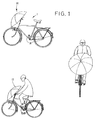
- a two-wheeler is shown, which in the following as Vehicle 1 is called.
- Vehicle 1 This can be a bike, a moped or even one equipped with three wheels Act bicycle or the like.
- a screen 16 is arranged, which in FIG. 1 is spanned Screen covering 17 is shown.
- the handle 4 of the screen 16 is as Locking piston 6 formed when using the screen serves as a normal umbrella as a normal umbrella handle, the one Has receiving opening 18 and with a locking groove 12 is equipped.
- a screen tube closes the handle 4 of the screen 5, which is designed in a manner known per se and designed, for example, as a screen tube 5 of a pocket umbrella is, d. H. such a shield tube can, for. B. on his half Length telescoped and in this position be locked, with the screen covering 17 is spanned. This ensures that - how special 1 can be clearly seen - the screen 16 with its spanned Shield 17 relatively close to the holding device 2 is arranged.
- the holding device 2 is in the illustrated embodiment 2 on a handlebar support 15 for one only arranged schematically indicated handlebar 14 and this Holding device 2 has a hook nose directed forward 8, which has a hook web 10 and an upward Has hook 9.
- This hook nose 8 can through the receiving opening 18 of the locking piston 6 are used and then engages with the actual hook 9 on the outside of the Locking piston 6 at the front of the same, so that at inserted locking piston 6 a removal of the locking piston 6 forward is not possible.
- a locking lug 19 engages, which is on a locking bar 7 is arranged, the bolt 7 by return springs 11 (Fig. 4) is guided into its position shown in Fig. 2, in which engages the locking lug 19 in the locking groove 12 and thus sets the locking piston 6 against upward movements.
- the locking lug 19 is from the top rear to the front bottom beveled so that when the closing piston 6 is inserted Bottom edge of the locking piston the bolt 7 against the action the return spring 11 moves back and then - as soon as the latch 19 arrives in the area of the locking groove 12 - again is moved forward and thereby sets the locking piston 6.
- the handle 4 is inserted and locked the screen 16 in the simplest possible way.
- the actual screen covering 17 can be in signal colors be trained so that just in bad weather and open screen 16 an additional security for the User of the vehicle 1 is reached.
- the actual holding device 2 instead of on the handlebar bracket 15, the actual holding device 2 also on the head tube of vehicle 1 or whose handlebars 14 are arranged.
- a joint can be seen at 20, which is the possibility gives that the actual screen 16 in different inclinations can be arranged in front of the user of the vehicle.
- the handle 4 of the screen and thus the locking piston 6 compared to that connected to the shield tube 5 Umbrella are locked in the area of the joint 20 so that the individual, set positions are fixed and secured.
- a such locking is in Fig. 3 by the indicated wheel 21 clarifies
- the locking piston 6 forms together with the holding device 2 a ratchet lock that can be locked quickly and quickly is solvable, only one embodiment in FIGS. 2 to 5 of such a ratchet closure is shown.
- a carrier 23 is shown on a much larger scale in FIG. with the interposition of a holding device 2 connects to a handlebar bracket 15. Between the carrier 23 and the holding device 2, a lockable joint 20 is switched on.
- the carrier 23 has a receptacle 21 which is the handle of a Umbrella is adapted and takes this handle.
- the carrier 23 consists of an elongated support element 25, which has a clamping device 22 at its front end carries, in which the shield tube 5, for example by means of an eccentric closure 24 can be set.
- This support element 25 can be used in any way when not in use Length can be reduced and can also be effective Length adjustable, z. B. in that it is telescopically displaceable is.
- a sliding sleeve is indicated on the connect the spokes of the screen and those on the top one Shield tube is slidable, with the shown Embodiment the individual, the shield tube 5 forming Telescopic tubes are pushed together so far that the top shield tube 5 and thus also the clamped Umbrella is arranged as close as possible in front of the handlebar support.
- the umbrella keep as close as possible to the knees of the vehicle user, with the double support on the one hand in the recording 21, on the other hand in the clamping device 22, the screen safely and is firmly held so that even cross winds do not block the glider can move out of their holder.
- the holding device 2 can connect to the handlebar bracket 15 and a locking piston 6 can be arranged on the carrier 23, which has a receiving opening 18 and with a locking groove 12 is equipped, as shown in Fig. 2 to 5.
- the actual holding device 2 instead of on the handlebar bracket 15, the actual holding device 2 also on the head tube of the vehicle 1 or on the latter Handlebar 14 are arranged.
Landscapes
- Engineering & Computer Science (AREA)
- Mechanical Engineering (AREA)
- Walking Sticks, Umbrellas, And Fans (AREA)
- Holders For Apparel And Elements Relating To Apparel (AREA)
- Vehicle Step Arrangements And Article Storage (AREA)
Abstract
Description
Die Erfindung bezieht sich auf eine Schirmhalterung für ein gegen
Witterungseinflüsse ungeschütztes Fahrzeug wie ein Zweirad
od. dgl. gemäß dem Oberbegriff des Hauptanspruches und
dem Oberbegriff des Anspruches 2.The invention relates to an umbrella holder for a against
Unprotected vehicle like a two-wheeler
od. Like. According to the preamble of the main claim and
the preamble of
Aus der DE 36 20 513 A1 ist eine gattungsbildende Schirmhalterung bekanntgeworden, bei welcher ein üblicher Regenschirm an seinem Griff an dem Fahrzeug befestigbar und einstellbar ist. Hierbei wird der Schirm bei voller Länge des Schirmrohres aufgespannt und kann auch nach vorne verstellt werden, wobei aber als nachteilig empfunden wird, daß dabei die Beine des Zweiradbenutzers überhaupt nicht geschützt sind.DE 36 20 513 A1 is a generic umbrella holder became known, in which a common umbrella can be attached to its handle on the vehicle and is adjustable. Here, the screen is stretched with the full length of the screen tube and can also be adjusted forward, whereby but it is considered disadvantageous that the legs of the Two-wheeler users are not protected at all.
Durch die relativ weite Entfernung der Schirmbespannung von der Schirmhalterung und damit auch von der das Zweirad benutzenden Person wird neben der Tatsache, daß ein ungenügender Schutz gegen Regen oder Schnee bedingt wird, außerdem zwangsläufig bedingt, daß der Schirm eine relativ große Angriffsfläche relativ weit entfernt von seinem Befestigungspunkt dem Wind od. dgl. darbietet, so daß dadurch die Stabilität des Zweirades erheblich beeinträchtigt wird und die sichere Halterung des Schirmes beeinträchtigt wird.Due to the relatively large distance of the screen covering from the umbrella holder and thus also the one using the two-wheeler Person becomes besides the fact that an insufficient Protection against rain or snow is also required inevitably caused that the screen a relatively large Attack area relatively far from its attachment point the wind or the like., so that thereby the stability of the two-wheeler is significantly impaired and the safe Bracket of the screen is affected.
Auch die Anbringung des Schirmes an seiner Schirmhalterung am Zweirad ist nur aufwendig zu betätigen. Also attaching the umbrella to its umbrella holder on the two-wheeler is only laborious to operate.
Aus der DE 89 14 316 U1 ist ein Regenschirmhalter für Tourenfahrräder bekannt geworden, bei dem der eigentliche Halter am Schirmrohr angreift. Neben den Nachteilen, wie sie vorstehend zur DE 36 20 513 A1 erläutert sind, hat diese Anordnung den Nachteil, daß die Halterung am Schirmrohr nicht die aussreichende Stabilität schafft, sondern der Schirm kann bei entsprechender Windbelastung abknicken.DE 89 14 316 U1 is an umbrella holder for touring bicycles became known, in which the actual holder on Shield tube attacks. In addition to the drawbacks as outlined above to DE 36 20 513 A1, this arrangement has the Disadvantage that the bracket on the screen tube is not sufficient Creates stability, but the screen can with appropriate Bend off the wind load.
Der Erfindung liegt die Aufgabe zugrunde, eine Schirmhalterung zu schaffen, die in Verbindung mit einem angepaßten Schirm ein schnelles Anschließen des Schirmes am Zweirad ermöglicht, wobei der Anschluß auch von technisch Unbegabten und Kindern durchgeführt werden soll und wobei weiterhin der Schirm, trotzdem es sich hinsichtlich des Schirmrohres und der Bespannung um einen handelsüblichen Schirm handelt, nahe vor den Knien der das Zweirad benutzenden Person aufgespannt werden kann.The invention has for its object a screen holder to create that in conjunction with a customized screen enables a quick connection of the screen to the two-wheeler, the connection also by technically unskilled and Children should be carried out and the Umbrella, nevertheless it is with regard to the umbrella tube and the Covering is a commercial umbrella, close stretched out in front of the knees of the person using the two-wheeler can be.
Diese der Erfindung zugrundeliegende Aufgabe wird durch die Lehre des Hauptanspruches gelöst.This object of the invention is achieved by Teaching of the main claim solved.
Vorteilhafte Ausgestaltungen der Erfindung sind in den Unteransprüchen erläutert.Advantageous embodiments of the invention are in the subclaims explained.
Mit anderen Worten ausgedrückt wird vorgeschlagen, daß der Schirmgriff als Schließkolben ausgebildet ist und am Zweirad, vorzugsweise am Lenkerträger oder am Steuerrohr oder sogar am Lenker eine Haltevorrichtung fest angeordnet ist, in die der Schließkolben in einfachster Weise eingesetzt werden kann, wobei diese Haltevorrichtung mit einem gegen die Wirkung mindestens einer Rückstellfeder zurückschiebbaren Riegel ausgerüstet ist, der in eine entsprechende Riegelnut des Schließkolbens eingreift. In other words, it is suggested that the Umbrella handle is designed as a locking piston and on the two-wheeler, preferably on the handlebar or on the head tube or even on the handlebar a holding device is fixed, in which the Locking piston can be used in the simplest way, this holding device with at least one against the effect a return spring retractable latch equipped is in a corresponding locking groove of the locking piston intervenes.
Der eigentliche Griff des Schirmes weist dabei eine Aufnahmeöffnung auf, in die eine Hakennase der Haltevorrichtung eingesetzt werden kann, wobei die Hakennase mit einem nach oben ausgerüsteten Haken am Hakensteg versehen ist, so daß dadurch eine Sicherung des Griffes des Schirmes nach vorne hin erreicht wird, da der Schließkolben durch die Hakennase nach vorne hin festgelegt wird. Zur Rückseite hin liegt der Schließkolben an der eigentlichen Haltevorrichtung an, die an dem Zweirad befestigt ist und die Absicherung des Schließkolbens und damit des Griffes des Schirmes nach oben hin erfolgt durch einen Riegel, der mit seiner Riegelnase in eine Riegelnut am Schließkolben eingreift.The actual handle of the screen has a receiving opening into which a hook nose of the holding device is inserted can be, with the hooked nose facing upwards equipped hook is provided on the hook web, so that securing the handle of the umbrella to the front is reached, because the locking piston follows through the hook nose is determined at the front. The locking piston is located towards the rear on the actual holding device on the two-wheeler is attached and the protection of the locking piston and so that the handle of the umbrella is made by a Bolt that with its bolt nose into a bolt groove on Engages locking piston.
Der Riegel ist leicht zurückzuschieben und - da die Riegelnase abgeschrägt ausgebildet ist - wird sie beim Einsetzen des Schließkolbens automatisch nach hinten bewegt, d. h. also das Einsetzen des Griffes des Schirmes kann ohne Handbetätigung des Riegels allein durch Einschieben des Schließkolbens erreicht werden.The bolt is easy to push back and - because the bolt nose is bevelled - it is when inserting the Closing piston moves automatically backwards, d. H. so that The handle of the umbrella can be inserted without manual operation of the bolt is achieved simply by inserting the locking piston become.
Eine abgeänderte Ausführungsform wird in dem unabhängigen
Anspruch 2 und den Unteransprüchen definiert.A modified embodiment is in the
Gemäß dieser abgewandelten Ausführungsform wird vorgeschlagen, daß vor dem Lenkerträger, Lenker oder dem Steuerrohr ein Träger angeordnet wird, in den der Schirm einsetzbar ist, wobei dieser Träger vorzugsweise mit einer topfförmigen Aufnahme ausgerüstet ist, die den eigentlichen Griff des Schirmes aufnimmt und weiterhin eine Klemmvorrichtung aufweist, die relativ nahe an der Schiebemuffe des Schirmes angreift, so daß also das Schirmrohr an zwei Stellen festgelegt wird, einmal unten am Griff und einmal relativ weit vorne, wobei aber das Schirmrohr wie üblich teleskopartig ausgebildet ineinandergeschoben wird, so daß sich der Schirm im aufgespannten Zustand möglichst nahe vor dem Lenker und damit vor den Knien des das Fahrzeug Benutzenden befindet. According to this modified embodiment, it is proposed that that in front of the handlebar support, handlebar or the head tube a carrier is arranged in which the screen can be used is, this carrier preferably with a cup-shaped Recording is equipped, which is the actual handle of the umbrella picks up and also has a clamping device, which attacks relatively close to the sliding sleeve of the screen, so that the screen tube is fixed in two places, once at the bottom of the handle and once relatively far forward, but that Shield tube telescopically pushed as usual is, so that the screen in the open state as close as possible to the handlebars and therefore to the knees of the user of the vehicle.
Hierbei kann so vorgegangen werden, daß der Träger unter Zwischenschaltung einer Gelenkverbindung über eine Arretiervorrichtung und Haltevorrichtung am Lenkerrohr, Lenker oder Steuerrohr festgelegt wird, die leicht lösbar ist oder aber der Träger wird am Steuerrohr oder Lenkerrohr festgelegt und kann am Fahrzeug verbleiben.This can be done so that the carrier under Interposition of an articulated connection via a locking device and holding device on the handlebar tube, handlebar or Head tube is set that is easily detachable or the Carrier is attached to the head tube or handlebar tube and can remain on the vehicle.
Es erscheint sehr vorteilhaft, daß die Klemmvorrichtung mit einem Exzenterverschluß ausgerüstet ist und daß zusätzlich am Träger Haltevorrichtungen, beispielsweise Bänder oder Clipsvorrichtungen vorgesehen sind, die den Schirm aufnehmen wenn dieser bei Nichtgebrauch zusammengeschoben ist, so daß der Schirm am Fahrzeug stets griffbereit untergebracht ist.It seems very advantageous that the clamping device with a Eccentric closure is equipped and that in addition on Carrier holding devices, for example tapes or clip devices are provided that accommodate the screen if this is pushed together when not in use, so that the screen on the vehicle is always within reach.
Bei Nichtgebrauch des Trägers kann dieser vorteilhafterweise zusammengeklappt oder teleskopierend ineinandergeschoben werden, so daß der durch den Träger gebildete Vorsprung verringert wird.When the carrier is not in use, it can advantageously be used folded or telescopically pushed together be reduced so that the projection formed by the carrier becomes.
Bei der erfindungsgemäßen Anordnung kann es vorteilhaft sein, die eigentliche Schirmbespannung zusätzlich in Signalfarben auszubilden, wodurch insbesondere bei Schülern und in der Abenddämmerung und nachts eine bessere Sicht des Zweiradfahrers erreicht wird.In the arrangement according to the invention, it can be advantageous the actual screen covering also in signal colors to train, which is particularly useful for students and students Dusk and at night a better view of the two-wheeler is achieved.
Ausführungsbeispiele der Erfindung werden nachfolgend anhand der Zeichnungen erläutert. Die Zeichnungen zeigen dabei in
- Fig. 1
- die erfindungsgemäße Anordnung eines Schirmes an einem Zweirad, in
- Fig. 2
- in größerem Maßstab und in einer Schnittdarstellung die Anordnung der Haltevorrichtung an einem Lenkerträger, in
- Fig. 3
- eine Ansicht auf die Anordnung in Fig. 2 von vorne gesehen, in
- Fig. 4
- eine Schnittdarstellung durch den Riegel mit den zugeordneten Rückstellfedern, in
- Fig. 5
- eine Ansicht von unten auf die Anordnung gemäß Fig. 4 und in
- Fig. 6
- einen am Lenkerträger angeordneten Träger.
- Fig. 1
- the inventive arrangement of a screen on a two-wheeler, in
- Fig. 2
- on a larger scale and in a sectional view the arrangement of the holding device on a handlebar support, in
- Fig. 3
- a view of the arrangement in Fig. 2 seen from the front, in
- Fig. 4
- a sectional view through the bolt with the associated return springs, in
- Fig. 5
- a bottom view of the arrangement of FIG. 4 and in
- Fig. 6
- a carrier arranged on the handlebar support.
In Fig. 1 ist ein Zweirad dargestellt, das im nachfolgenden als
Fahrzeug 1 bezeichnet wird. Hierbei kann es sich um ein Fahrrad,
ein Moped oder auch um ein mit drei Rädern ausgerüstetes
Fahrrad od. dgl. handeln. An der Vorderseite dieses Fahrzeuges
1 ist ein Schirm 16 angeordnet, der in Fig. 1 mit aufgespannter
Schirmbespannung 17 dargestellt ist.In Fig. 1 a two-wheeler is shown, which in the following as
Vehicle 1 is called. This can be a bike,
a moped or even one equipped with three wheels
Act bicycle or the like. At the front of this vehicle
1, a
In wesentlich größerem Maßstab ist in den Fig. 2 bis 5 eine
Haltevorrichtung 2 für den Schirm 16 dargestellt, wobei die Haltevorrichtung
2 eine Arretiervorrichtung 3 für einen Griff 4 des
Schirmes 16 aufweist. Der Griff 4 des Schirmes 16 ist als
Schließkolben 6 ausgebildet, der bei Benutzung des Schirmes
als normaler Handschirm als normaler Schirmgriff dient, der eine
Aufnahmeöffnung 18 aufweist und mit einer Riegelnut 12
ausgerüstet ist. An den Griff 4 des Schirmes schließt ein Schirmrohr
5 an, das in an sich bekannter Weise ausgebildet ist und
beispielsweise als Schirmrohr 5 eines Taschenschirmes gestaltet
ist, d. h. ein solches Schirmrohr kann z. B. auf seine halbe
Länge teleskopartig zusammengeschoben und in dieser Stellung
arretiert werden, wobei trotzdem die Schirmbespannung 17
aufgespannt ist. Hierdurch wird erreicht, daß - wie besonders
deutlich aus Fig. 1 ersichtlich ist - der Schirm 16 mit seiner aufgespannten
Beschirmung 17 relativ nahe an der Haltevorrichtung
2 angeordnet ist.2 to 5 is a much larger
Die Haltevorrichtung 2 ist bei dem dargestellten Ausführungsbeispiel
gemäß Fig. 2 an einem Lenkerträger 15 für einen nur
schematisch angedeuteten Lenker 14 angeordnet und diese
Haltevorrichtung 2 weist eine nach vorne gerichtete Hakennase
8 auf, die einen Hakensteg 10 und einen nach oben gerichteten
Haken 9 besitzt. Diese Hakennase 8 kann durch die Aufnahmeöffnung
18 des Schließkolbens 6 eingesetzt werden und
greift dann mit dem eigentlichen Haken 9 an der Außenseite des
Schließkolbens 6 an der Vorderseite desselben an, so daß bei
eingesetztem Schließkolben 6 eine Entfernung des Schließkolbens
6 nach vorne hin nicht möglich ist.The
In die Riegelnut 12 greift eine Riegelnase 19, die an einem Riegel
7 angeordnet ist, wobei der Riegel 7 durch Rückstellfedern
11 (Fig. 4) in seine in Fig. 2 dargestellte Stellung geführt wird, in
der die Riegelnase 19 in die Riegelnut 12 eingreift und damit
den Schließkolben 6 gegen Bewegungen nach oben hin festlegt.In the locking groove 12 a
Hierbei ist die Riegelnase 19 von hinten oben nach vorne unten
abgeschrägt, so daß bei Einsetzen des Schließkolbens 6 die
Unterkante des Schließkolbens den Riegel 7 gegen die Wirkung
der Rückstellfeder 11 zurückbewegt und dann - sobald die Riegelnase
19 in dem Bereich der Riegelnut 12 gelangt - wieder
nach vorne bewegt wird und dadurch den Schließkolben 6 festlegt.
Hierdurch ist ein Einsetzen und Verriegeln des Griffes 4
des Schirmes 16 in einfachster Weise möglich.Here, the
Die eigentliche Schirmbespannung 17 kann in Signalfarben
ausgebildet sein, so daß gerade bei schlechtem Wetter und
aufgespanntem Schirm 16 eine zusätzliche Sicherheit für den
Benutzer des Fahrzeuges 1 erreicht wird.The actual screen covering 17 can be in signal colors
be trained so that just in bad weather and
Anstelle an dem Lenkerträger 15 kann die eigentliche Haltevorrichtung
2 auch am Steuerrohr des Fahrzeuges 1 oder an
dessen Lenker 14 angeordnet werden.Instead of on the
In Fig. 2 ist bei 20 ein Gelenk erkennbar, das die Möglichkeit
gibt, daß der eigentliche Schirm 16 in verschiedenen Neigungen
vor dem Benutzer des Fahrzeuges angeordnet werden kann.
Natürlich kann der Griff 4 des Schirmes und damit der Schließkolben
6 gegenüber dem mit dem Schirmrohr 5 verbundenen
Schirm im Bereich des Gelenkes 20 arretiert werden, so daß die
einzelnen, eingestellten Stellungen fest und gesichert sind. Eine
solche Arretierung ist in Fig. 3 durch das angedeutete Stellrad
21 verdeutlichtIn Fig. 2 a joint can be seen at 20, which is the possibility
gives that the
Der Schließkolben 6 bildet zusammen mit der Haltevorrichtung
2 einen Ratschenverschluß, der schnell verrastbar und schnell
lösbar ist, wobei in den Fig. 2 bis 5 nur ein Ausführungsbeispiel
eines solchen Ratschenverschlusses dargestellt ist.The
In wesentlich größerem Maßstab ist in Fig. 6 ein Träger 23 dargestellt,
der unter Zwischenschaltung einer Haltevorrichtung 2
an einen Lenkerträger 15 anschließt. Zwischen dem Träger 23
und der Haltevorrichtung 2 ist ein arretierbares Gelenk 20 eingeschaltet.A
Der Träger 23 weist eine Aufnahme 21 auf, die dem Griff eines
Schirmes angepaßt ist und diesen Griff aufnimmt. Weiterhin
besteht der Träger 23 aus einem langgestreckten Tragelement
25, das an seinem vorderen Ende eine Klemmvorrichtung 22
trägt, in der das Schirmrohr 5 beispielsweise mittels eines Exzenterverschlusses
24 festgelegt werden kann. Dieses Tragelement
25 kann bei Nichtgebrauch in irgendeiner Weise in seiner
Länge verringert werden und kann auch in seiner wirksamen
Länge einstellbar sein, z. B. dadurch, daß es teleskopartig verschiebbar
ist. Bei 26 ist eine Schiebemuffe angedeutet, an der
die Speichen des Schirmes anschließen und die auf dem obersten
Schirmrohr verschiebbar ist, wobei bei dem dargestellten
Ausführungsbeispiel die einzelnen, das Schirmrohr 5 bildenden
Teleskoprohre so weit ineinandergeschoben sind, daß das
oberste Schirmrohr 5 und damit auch dann der aufgespannte
Schirm möglichst nahe vor dem Lenkerträger angeordnet ist. Auf
diese Weise ist es möglich, in einfachster weise den Schirm
möglichst nahe vor den Knien des Fahrzeugbenutzers zu halten,
wobei durch die doppelte Abstützung einerseits in der Aufnahme
21, andererseits in der Klemmvorrichtung 22, der Schirm sicher
und fest gehaltert ist, so daß auch Querwinde den Schirm nicht
aus ihrer Halterung heraus bewegen können.The
Die Haltevorrichtung 2 kann am Lenkerträger 15 anschließen
und am Träger 23 kann ein Schließkolben 6 angeordnet sein,
der eine Aufnahmeöffnung 18 aufweist und mit einer Riegelnut
12 ausgerüstet ist, so wie in Fig. 2 bis 5 dargestellt.The holding
Anstelle an dem Lenkerträger 15 kann die eigentliche Haltevorrichtung
2 auch am Steuerrohr des Fahrzeuges 1 oder an dessen
Lenker 14 angeordnet werden.Instead of on the
Claims (13)
Applications Claiming Priority (8)
| Application Number | Priority Date | Filing Date | Title |
|---|---|---|---|
| DE29820158U | 1998-11-11 | ||
| DE29820158 | 1998-11-11 | ||
| DE29821094U | 1998-11-25 | ||
| DE29821094U DE29821094U1 (en) | 1998-11-11 | 1998-11-25 | Umbrella holder for a two-wheeler or the like. |
| DE29823169 | 1998-12-29 | ||
| DE29823169U | 1998-12-29 | ||
| DE29900541U | 1999-01-15 | ||
| DE29900541U DE29900541U1 (en) | 1998-12-29 | 1999-01-15 | Umbrella holder for a two-wheeler or the like. |
Publications (3)
| Publication Number | Publication Date |
|---|---|
| EP1000844A2 true EP1000844A2 (en) | 2000-05-17 |
| EP1000844A3 EP1000844A3 (en) | 2002-01-02 |
| EP1000844B1 EP1000844B1 (en) | 2004-02-25 |
Family
ID=27439198
Family Applications (1)
| Application Number | Title | Priority Date | Filing Date |
|---|---|---|---|
| EP99122193A Expired - Lifetime EP1000844B1 (en) | 1998-11-11 | 1999-11-06 | Umbrella holding device for bicycle |
Country Status (2)
| Country | Link |
|---|---|
| EP (1) | EP1000844B1 (en) |
| AT (1) | ATE260202T1 (en) |
Cited By (2)
| Publication number | Priority date | Publication date | Assignee | Title |
|---|---|---|---|---|
| DE102017112836A1 (en) * | 2017-06-12 | 2018-12-13 | Gerhard Seedorff | Lockable carrier adapter for basket for secure attachment to a bicycle rack |
| CN112790491A (en) * | 2021-03-05 | 2021-05-14 | 福建省晋江市东石兴隆雨具制造有限公司 | Easily fixed and but height-adjusting's umbrella of riding |
Citations (2)
| Publication number | Priority date | Publication date | Assignee | Title |
|---|---|---|---|---|
| DE3620513A1 (en) | 1985-07-05 | 1987-01-15 | Dieter Winterkamp | UMBRELLA MOUNT FOR A BICYCLE OR THE LIKE OPEN VEHICLE |
| DE8914316U1 (en) | 1989-11-28 | 1990-10-31 | Szponik, Josef, 4005 Meerbusch | Umbrella holder for touring bikes |
Family Cites Families (2)
| Publication number | Priority date | Publication date | Assignee | Title |
|---|---|---|---|---|
| GB2010200B (en) * | 1977-11-07 | 1982-07-14 | Arakawa Ind Co Ltd | Umbrella supporting devices for bicycles |
| DE29803870U1 (en) * | 1998-03-05 | 1998-10-08 | Lander, Otto, 70736 Fellbach | Multi-adjustable rain and parasol holder for bicycles |
-
1999
- 1999-11-06 AT AT99122193T patent/ATE260202T1/en not_active IP Right Cessation
- 1999-11-06 EP EP99122193A patent/EP1000844B1/en not_active Expired - Lifetime
Patent Citations (2)
| Publication number | Priority date | Publication date | Assignee | Title |
|---|---|---|---|---|
| DE3620513A1 (en) | 1985-07-05 | 1987-01-15 | Dieter Winterkamp | UMBRELLA MOUNT FOR A BICYCLE OR THE LIKE OPEN VEHICLE |
| DE8914316U1 (en) | 1989-11-28 | 1990-10-31 | Szponik, Josef, 4005 Meerbusch | Umbrella holder for touring bikes |
Cited By (2)
| Publication number | Priority date | Publication date | Assignee | Title |
|---|---|---|---|---|
| DE102017112836A1 (en) * | 2017-06-12 | 2018-12-13 | Gerhard Seedorff | Lockable carrier adapter for basket for secure attachment to a bicycle rack |
| CN112790491A (en) * | 2021-03-05 | 2021-05-14 | 福建省晋江市东石兴隆雨具制造有限公司 | Easily fixed and but height-adjusting's umbrella of riding |
Also Published As
| Publication number | Publication date |
|---|---|
| EP1000844A3 (en) | 2002-01-02 |
| ATE260202T1 (en) | 2004-03-15 |
| EP1000844B1 (en) | 2004-02-25 |
Similar Documents
| Publication | Publication Date | Title |
|---|---|---|
| DE69702058T2 (en) | UMBRELLA ROOF FOR BICYCLES | |
| DE3043465A1 (en) | PARASOL | |
| DE202014102484U1 (en) | Weather protection device for detachable attachment to a two- or multi-wheel | |
| DE19836473B4 (en) | Wind stop device | |
| EP1000844B1 (en) | Umbrella holding device for bicycle | |
| DE202008000612U1 (en) | Foldable and removable spoiler screen for vehicles, especially bicycles, strollers and the like. | |
| AT393482B (en) | ROOFING TWO WHEELS TO PROTECT AGAINST RAIN, SNOW AND WIND | |
| DE202015004987U1 (en) | Umbrella construction for protection against rain and wind | |
| DE4241235C2 (en) | Lockable storage device for protective helmets on two-wheelers, etc. | |
| DE102013112665B4 (en) | Bicycle handlebar system | |
| DE29821094U1 (en) | Umbrella holder for a two-wheeler or the like. | |
| DE29900541U1 (en) | Umbrella holder for a two-wheeler or the like. | |
| CH712600A2 (en) | Rain cover for mounting on a vehicle. | |
| WO2003092830A1 (en) | Ski clip | |
| DE19719333A1 (en) | Mounting device for attaching umbrella on pram | |
| DE4310487A1 (en) | Box-like storage apparatus for two-wheelers, such as bicycles, mopeds or motorbikes | |
| DE19841780A1 (en) | Hybrid motorised tricycle | |
| DE19504887A1 (en) | Dismantlable rain and/or weather protection for bicycle | |
| DE102015004231A1 (en) | Rain protection device for bicycles or other open vehicles | |
| EP0349602A1 (en) | Mudguard for bicycles | |
| DE29610495U1 (en) | Umbrella roof for bicycles or the like. | |
| DE8226078U1 (en) | Bracket for bicycles | |
| DE8517785U1 (en) | Collapsible toboggan | |
| DE29804498U1 (en) | Sun visor device for a rear window of a vehicle | |
| DE102015111596A1 (en) | Weather protection device for detachable attachment to a two- or multi-wheel |
Legal Events
| Date | Code | Title | Description |
|---|---|---|---|
| PUAI | Public reference made under article 153(3) epc to a published international application that has entered the european phase |
Free format text: ORIGINAL CODE: 0009012 |
|
| AK | Designated contracting states |
Kind code of ref document: A2 Designated state(s): AT BE CH CY DE DK ES FI FR GB GR IE IT LI LU MC NL PT SE |
|
| AX | Request for extension of the european patent |
Free format text: AL;LT;LV;MK;RO;SI |
|
| PUAL | Search report despatched |
Free format text: ORIGINAL CODE: 0009013 |
|
| AK | Designated contracting states |
Kind code of ref document: A3 Designated state(s): AT BE CH CY DE DK ES FI FR GB GR IE IT LI LU MC NL PT SE |
|
| AX | Request for extension of the european patent |
Free format text: AL;LT;LV;MK;RO;SI |
|
| 17P | Request for examination filed |
Effective date: 20020119 |
|
| AKX | Designation fees paid |
Free format text: AT BE CH CY DE DK ES FI FR GB GR IE IT LI LU MC NL PT SE |
|
| GRAP | Despatch of communication of intention to grant a patent |
Free format text: ORIGINAL CODE: EPIDOSNIGR1 |
|
| GRAS | Grant fee paid |
Free format text: ORIGINAL CODE: EPIDOSNIGR3 |
|
| GRAA | (expected) grant |
Free format text: ORIGINAL CODE: 0009210 |
|
| AK | Designated contracting states |
Kind code of ref document: B1 Designated state(s): AT BE CH CY DE DK ES FI FR GB GR IE IT LI LU MC NL PT SE |
|
| PG25 | Lapsed in a contracting state [announced via postgrant information from national office to epo] |
Ref country code: IT Free format text: LAPSE BECAUSE OF FAILURE TO SUBMIT A TRANSLATION OF THE DESCRIPTION OR TO PAY THE FEE WITHIN THE PRESCRIBED TIME-LIMIT;WARNING: LAPSES OF ITALIAN PATENTS WITH EFFECTIVE DATE BEFORE 2007 MAY HAVE OCCURRED AT ANY TIME BEFORE 2007. THE CORRECT EFFECTIVE DATE MAY BE DIFFERENT FROM THE ONE RECORDED. Effective date: 20040225 Ref country code: IE Free format text: LAPSE BECAUSE OF FAILURE TO SUBMIT A TRANSLATION OF THE DESCRIPTION OR TO PAY THE FEE WITHIN THE PRESCRIBED TIME-LIMIT Effective date: 20040225 Ref country code: GB Free format text: LAPSE BECAUSE OF FAILURE TO SUBMIT A TRANSLATION OF THE DESCRIPTION OR TO PAY THE FEE WITHIN THE PRESCRIBED TIME-LIMIT Effective date: 20040225 Ref country code: FR Free format text: LAPSE BECAUSE OF FAILURE TO SUBMIT A TRANSLATION OF THE DESCRIPTION OR TO PAY THE FEE WITHIN THE PRESCRIBED TIME-LIMIT Effective date: 20040225 Ref country code: FI Free format text: LAPSE BECAUSE OF FAILURE TO SUBMIT A TRANSLATION OF THE DESCRIPTION OR TO PAY THE FEE WITHIN THE PRESCRIBED TIME-LIMIT Effective date: 20040225 Ref country code: CY Free format text: LAPSE BECAUSE OF FAILURE TO SUBMIT A TRANSLATION OF THE DESCRIPTION OR TO PAY THE FEE WITHIN THE PRESCRIBED TIME-LIMIT Effective date: 20040225 |
|
| REG | Reference to a national code |
Ref country code: GB Ref legal event code: FG4D Free format text: NOT ENGLISH |
|
| REG | Reference to a national code |
Ref country code: CH Ref legal event code: EP |
|
| REG | Reference to a national code |
Ref country code: IE Ref legal event code: FG4D Free format text: GERMAN |
|
| REF | Corresponds to: |
Ref document number: 59908634 Country of ref document: DE Date of ref document: 20040401 Kind code of ref document: P |
|
| PG25 | Lapsed in a contracting state [announced via postgrant information from national office to epo] |
Ref country code: SE Free format text: LAPSE BECAUSE OF FAILURE TO SUBMIT A TRANSLATION OF THE DESCRIPTION OR TO PAY THE FEE WITHIN THE PRESCRIBED TIME-LIMIT Effective date: 20040525 Ref country code: GR Free format text: LAPSE BECAUSE OF FAILURE TO SUBMIT A TRANSLATION OF THE DESCRIPTION OR TO PAY THE FEE WITHIN THE PRESCRIBED TIME-LIMIT Effective date: 20040525 Ref country code: DK Free format text: LAPSE BECAUSE OF FAILURE TO SUBMIT A TRANSLATION OF THE DESCRIPTION OR TO PAY THE FEE WITHIN THE PRESCRIBED TIME-LIMIT Effective date: 20040525 |
|
| PG25 | Lapsed in a contracting state [announced via postgrant information from national office to epo] |
Ref country code: ES Free format text: LAPSE BECAUSE OF FAILURE TO SUBMIT A TRANSLATION OF THE DESCRIPTION OR TO PAY THE FEE WITHIN THE PRESCRIBED TIME-LIMIT Effective date: 20040605 |
|
| GBV | Gb: ep patent (uk) treated as always having been void in accordance with gb section 77(7)/1977 [no translation filed] |
Effective date: 20040225 |
|
| REG | Reference to a national code |
Ref country code: IE Ref legal event code: FD4D |
|
| PG25 | Lapsed in a contracting state [announced via postgrant information from national office to epo] |
Ref country code: LU Free format text: LAPSE BECAUSE OF NON-PAYMENT OF DUE FEES Effective date: 20041106 Ref country code: AT Free format text: LAPSE BECAUSE OF NON-PAYMENT OF DUE FEES Effective date: 20041106 |
|
| PG25 | Lapsed in a contracting state [announced via postgrant information from national office to epo] |
Ref country code: MC Free format text: LAPSE BECAUSE OF NON-PAYMENT OF DUE FEES Effective date: 20041130 Ref country code: LI Free format text: LAPSE BECAUSE OF NON-PAYMENT OF DUE FEES Effective date: 20041130 Ref country code: CH Free format text: LAPSE BECAUSE OF NON-PAYMENT OF DUE FEES Effective date: 20041130 Ref country code: BE Free format text: LAPSE BECAUSE OF NON-PAYMENT OF DUE FEES Effective date: 20041130 |
|
| PLBE | No opposition filed within time limit |
Free format text: ORIGINAL CODE: 0009261 |
|
| STAA | Information on the status of an ep patent application or granted ep patent |
Free format text: STATUS: NO OPPOSITION FILED WITHIN TIME LIMIT |
|
| EN | Fr: translation not filed | ||
| 26N | No opposition filed |
Effective date: 20041126 |
|
| BERE | Be: lapsed |
Owner name: *KLAUS EGON Effective date: 20041130 |
|
| REG | Reference to a national code |
Ref country code: CH Ref legal event code: PL |
|
| BERE | Be: lapsed |
Owner name: *KLAUS EGON Effective date: 20041130 |
|
| PG25 | Lapsed in a contracting state [announced via postgrant information from national office to epo] |
Ref country code: PT Free format text: LAPSE BECAUSE OF NON-PAYMENT OF DUE FEES Effective date: 20040725 |
|
| PGFP | Annual fee paid to national office [announced via postgrant information from national office to epo] |
Ref country code: NL Payment date: 20101123 Year of fee payment: 12 |
|
| REG | Reference to a national code |
Ref country code: NL Ref legal event code: V1 Effective date: 20120601 |
|
| PG25 | Lapsed in a contracting state [announced via postgrant information from national office to epo] |
Ref country code: NL Free format text: LAPSE BECAUSE OF NON-PAYMENT OF DUE FEES Effective date: 20120601 |
|
| REG | Reference to a national code |
Ref country code: DE Ref legal event code: R084 Ref document number: 59908634 Country of ref document: DE Effective date: 20131116 |
|
| PGFP | Annual fee paid to national office [announced via postgrant information from national office to epo] |
Ref country code: DE Payment date: 20131223 Year of fee payment: 15 |
|
| REG | Reference to a national code |
Ref country code: DE Ref legal event code: R119 Ref document number: 59908634 Country of ref document: DE |
|
| PG25 | Lapsed in a contracting state [announced via postgrant information from national office to epo] |
Ref country code: DE Free format text: LAPSE BECAUSE OF NON-PAYMENT OF DUE FEES Effective date: 20150602 |