EP1000676A2 - Bending rolls, and pipe formed thereby - Google Patents
Bending rolls, and pipe formed thereby Download PDFInfo
- Publication number
- EP1000676A2 EP1000676A2 EP99308805A EP99308805A EP1000676A2 EP 1000676 A2 EP1000676 A2 EP 1000676A2 EP 99308805 A EP99308805 A EP 99308805A EP 99308805 A EP99308805 A EP 99308805A EP 1000676 A2 EP1000676 A2 EP 1000676A2
- Authority
- EP
- European Patent Office
- Prior art keywords
- pipe
- rolls
- roll
- bending
- diameter
- Prior art date
- Legal status (The legal status is an assumption and is not a legal conclusion. Google has not performed a legal analysis and makes no representation as to the accuracy of the status listed.)
- Withdrawn
Links
Images


Classifications
-
- B—PERFORMING OPERATIONS; TRANSPORTING
- B21—MECHANICAL METAL-WORKING WITHOUT ESSENTIALLY REMOVING MATERIAL; PUNCHING METAL
- B21D—WORKING OR PROCESSING OF SHEET METAL OR METAL TUBES, RODS OR PROFILES WITHOUT ESSENTIALLY REMOVING MATERIAL; PUNCHING METAL
- B21D3/00—Straightening or restoring form of metal rods, metal tubes, metal profiles, or specific articles made therefrom, whether or not in combination with sheet metal parts
-
- B—PERFORMING OPERATIONS; TRANSPORTING
- B21—MECHANICAL METAL-WORKING WITHOUT ESSENTIALLY REMOVING MATERIAL; PUNCHING METAL
- B21C—MANUFACTURE OF METAL SHEETS, WIRE, RODS, TUBES OR PROFILES, OTHERWISE THAN BY ROLLING; AUXILIARY OPERATIONS USED IN CONNECTION WITH METAL-WORKING WITHOUT ESSENTIALLY REMOVING MATERIAL
- B21C37/00—Manufacture of metal sheets, bars, wire, tubes or like semi-manufactured products, not otherwise provided for; Manufacture of tubes of special shape
- B21C37/06—Manufacture of metal sheets, bars, wire, tubes or like semi-manufactured products, not otherwise provided for; Manufacture of tubes of special shape of tubes or metal hoses; Combined procedures for making tubes, e.g. for making multi-wall tubes
- B21C37/08—Making tubes with welded or soldered seams
- B21C37/0807—Tube treating or manipulating combined with, or specially adapted for use in connection with tube making machines, e.g. drawing-off devices, cutting-off
- B21C37/0811—Tube treating or manipulating combined with, or specially adapted for use in connection with tube making machines, e.g. drawing-off devices, cutting-off removing or treating the weld bead
-
- B—PERFORMING OPERATIONS; TRANSPORTING
- B21—MECHANICAL METAL-WORKING WITHOUT ESSENTIALLY REMOVING MATERIAL; PUNCHING METAL
- B21C—MANUFACTURE OF METAL SHEETS, WIRE, RODS, TUBES OR PROFILES, OTHERWISE THAN BY ROLLING; AUXILIARY OPERATIONS USED IN CONNECTION WITH METAL-WORKING WITHOUT ESSENTIALLY REMOVING MATERIAL
- B21C37/00—Manufacture of metal sheets, bars, wire, tubes or like semi-manufactured products, not otherwise provided for; Manufacture of tubes of special shape
- B21C37/06—Manufacture of metal sheets, bars, wire, tubes or like semi-manufactured products, not otherwise provided for; Manufacture of tubes of special shape of tubes or metal hoses; Combined procedures for making tubes, e.g. for making multi-wall tubes
- B21C37/08—Making tubes with welded or soldered seams
- B21C37/0815—Making tubes with welded or soldered seams without continuous longitudinal movement of the sheet during the bending operation
-
- B—PERFORMING OPERATIONS; TRANSPORTING
- B21—MECHANICAL METAL-WORKING WITHOUT ESSENTIALLY REMOVING MATERIAL; PUNCHING METAL
- B21D—WORKING OR PROCESSING OF SHEET METAL OR METAL TUBES, RODS OR PROFILES WITHOUT ESSENTIALLY REMOVING MATERIAL; PUNCHING METAL
- B21D5/00—Bending sheet metal along straight lines, e.g. to form simple curves
- B21D5/14—Bending sheet metal along straight lines, e.g. to form simple curves by passing between rollers
-
- Y—GENERAL TAGGING OF NEW TECHNOLOGICAL DEVELOPMENTS; GENERAL TAGGING OF CROSS-SECTIONAL TECHNOLOGIES SPANNING OVER SEVERAL SECTIONS OF THE IPC; TECHNICAL SUBJECTS COVERED BY FORMER USPC CROSS-REFERENCE ART COLLECTIONS [XRACs] AND DIGESTS
- Y10—TECHNICAL SUBJECTS COVERED BY FORMER USPC
- Y10T—TECHNICAL SUBJECTS COVERED BY FORMER US CLASSIFICATION
- Y10T29/00—Metal working
- Y10T29/49—Method of mechanical manufacture
- Y10T29/49826—Assembling or joining
Definitions
- the present invention relates to a pipe forming apparatus which uses bending rolls, as well as to a pipe forming method and pipe formed by the apparatus or method. More particularly, the present invention relates to a pipe forming method which uses bending rolls including a pair of lower rolls arranged at one side of a sheet material and an upper roll arranged at the other side of the sheet material, intermediate between the pair of lower rolls, as well as to a pipe forming apparatus including the bending rolls and a pipe formed by the pipe forming apparatus or method.
- the pipe forming apparatus and method of the present invention are suitable for production of high-strength, thick-walled pipes.
- Mass production of pipes is generally carried out by using an electric welding mill when the pipe diameter is comparatively small, whereas UOE mills are used for pipes having comparatively large pipe diameters.
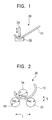
- a method as shown in Fig. 1 is employed for pipes having large wall thicknesses. More specifically, referring to Fig. 1, a blank sheet 10 is pressed between a bending die 22 and a pressing die 24 of a roll bender 20, and the pressing operation is repeated many times, e.g. 50 times or more, so as to bend the blank sheet into a pipe. In contrast, a method as illustrated in Fig. 2 is used when the wall thickness of the pipe is small. More specifically, referring to Fig.
- a pyramidal roll bender 30 employs three rolls: a pair of lower rolls 32 disposed under a blank sheet 10 and driven by a motor (not shown), and an upper roll 34 disposed on the upper side of the blank sheet 10 at a position intermediate between the pair of lower rolls 32.
- the tightening amount S i.e. the extent to which the upper roll 34 is lowered, is adjustable.
- the blank sheet 10 is threaded between the upper roll 34 and the lower rolls 32 so as to be continuously bent at a curvature radius ⁇ .
- a process of producing a pipe by the illustrated bending rolls is shown in Fig. 3.
- cutting and groove work are conducted by means of a flame planer 40 which cuts a blank sheet by using an oxygen or other gas plasma.
- an end bending operation is performed by, for example, a hydraulic press for bending the end of the blank sheet that cannot be bent by bending rolls.
- bending is effected by using, for example, a pyramidal roll bender 30 having three rolls as shown in Fig. 2.
- an inner/outer surface welder 46 performs tack welding and welding of inner and outer surfaces.
- end face milling is performed by an end face mill (not shown).
- the pipe thus formed is then shot-blasted in a shot-blast apparatus (not shown) and sent for testing and inspection.
- bend correction is performed subsequent to roll bending or tack welding, in order to enhance the circularity of the pipe. Such bend correction is conducted substantially in the same way as the roll bending.
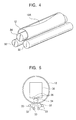
- this pipe forming method tends to allow an end gap 12A to occur in the center of the resulting pipe 12, as shown in Fig. 4, due to the difficulty of preventing deflection of the bending rolls, especially the upper roll 34. Therefore, this method is not suitable for use in the production of high-strength, thick-walled elongated pipe, which places a heavy load on the rolls and tends to cause deflection of the rolls.
- the pipe production method using a press bender is more suitable for the production of thick-walled pipes than the pipe-production method using a roll bender.
- it has a drawback in that the production efficiency is low due to the need for many pressing cycles, resulting in an elevated cost of production.
- Fig. 5 shows a pipe forming method which overcomes the above-described shortcoming of roll benders and which is disclosed in Japanese Kokai No. 53-128562.
- pressure is applied during the forming of a pipe to the upper roll 34 from the upper side thereof by means of a backup beam 36 via backup rolls 35.
- an upper roll of a greater diameter in accordance with an increase in the diameter of the pipe to be produced, thereby enabling production of high-strength, thick-walled, elongated pipes, by decreasing deflection of the upper roll.
- a pipe forming apparatus of the type using bending rolls including a plurality of rolls arranged on one side of a sheet material, and a counter roll arranged at the other side of the sheet material, comprising: a roll spacing setting device that sets the roll spacing of the pair of rolls to a range greater than the sum of the diameter of the counter roll and the diameter of one of the pair of rolls; and a device that sets the tightening amount of the counter roll relative to the pair of rolls to a range greater than the radius of one of the pair of rolls.
- the present invention enables forming the sheet material into a pipe with the pipe forming apparatus while setting the roll spacing between the pair of rolls to a value greater than the sum of the diameter of the counter roll and the diameter of each of the pair of rolls, and setting the amount of tightening to a value greater than the radius of each of the pair of rolls.
- the present invention in its second aspect provides a pipe forming method for forming a pipe using bending rolls including a plurality of rolls arranged on one side of a sheet material, and a counter roll arranged at the other side of the sheet material, the pipe forming method comprising: effecting pipe forming work on the sheet material such that the spacing L of the pair of rolls satisfies the following expression: (Dp + Dwl) > L ⁇ 0.85 (Dp + Dwl) where Dp represents the outside diameter of the produce pipe and Dwl represents the diameter of one of the pair of rolls.
- the present invention in its third aspect provides a pipe forming method for forming a pipe using bending rolls including a plurality of rolls arranged on one side of a sheet material, and a counter roll arranged at the other side of the sheet material, the pipe forming method comprising: preparing the sheet material having leading and trailing bent end regions, bent beforehand over a length not smaller than 1/5 of the entire circumference of the pipe to be produced; and effecting roll bending such that the length of the regions bent by the bending rolls is less than 3/5 the entire circumference of the pipe to be produced.
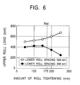
- Fig. 6 shows the results of an investigation conducted on the apparatus of Fig. 2,having a pair of rolls serving as lower rolls and an upper roll serving as a counter roll, for the purpose of clarifying the relationship between the amount S of tightening, i.e. the extent of lowering of the upper roll and the load acting on the upper roll, as observed when the spacing L between the lower rolls is held constant.
- the lower rolls 32 have a diameter Dwl of 350 mm
- the upper roll 34 has a diameter Dwu of 400 mm.
- An open circle ⁇ shows data obtained when the spacing L of the lower rolls was set to a value (specifically 600 mm) which is smaller than the sum of the diameters of the upper and lower rolls (750mm), as in the conventional arrangements.
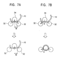
- the angle ⁇ of action of the load on the lower rolls is reduced, i.e., the upper roll is caused to penetrate more deeply into the region between the lower rolls, when the following conditions (1) and (2) are met:
- the load acting on the upper roll 34 is remarkably reduced when conditions (1) and (2) are satisfied simultaneously, so that the deflection of the upper roll 34 is significantly reduced. Therefore, the tendency of leaving an end gap is suppressed,even for pipes whose diameters are so small that the backup beam and large-diameter upper rolls cannot be used. For instance, it becomes possible to produce high-strength, thick-walled, elongated pipes such as 20 mm or greater in thickness, 40 kgf/mm 2 or higher in strength,and 5 m or longer in length.
- the apparatus is operated such that not only is the spacing between adjacent rolls in a pair always maintained greater than the sum of the diameter of the counter roll and the diameter of one of the pair of rolls, but also that the roll spacing is progressively decreased as the pass progresses, so that the final amount of tightening is greater than the radius of the pair of rolls.
- the pipe forming apparatus be operated such that the upper roll is lowered to a predetermined level in excess of the radius of the pair of rolls in earlier passes of the process, whereas in later passes the roll spacing is reduced.
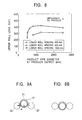
- Fig. 8 shows the relationship between the pipe diameter Dp and the load in each pass, as observed when a pipe is formed by bending roll apparatus while maintaining a constant spacing between lower rolls which serve as the pair of rolls.
- the load acting on the upper roll serving as the counter roll is greater for pipes having smaller diameters.
- the data marked by ⁇ indicates that the production of pipe is impossible.
- the ⁇ marks indicate data obtained when the lower roll spacing L has been increased to 800 mm. In this case, the load is reduced as compared with the case where the lower roll spacing is smaller. Furthermore, in this case the load is drastically reduced when the pipe diameter becomes smaller as a result of an increasing number of passes.
- the ⁇ marks indicate data obtained when the lower roll spacing is increased to 1000 mm. In this case, it is impossible to form the pipe to the final diameter, although the load is reduced as the number of passes increases.
- the angle ⁇ of action of the load on the lower rolls in the final stage of the process is decreased when the tightening amount S of the upper roll reaches a final value greater than the radius Rwl of the lower roll. That is, a geometrical relationship is established such that the upper roll falls down into the region between the lower rolls, thus making it possible to control the size of the end gap.
- This measure alone cannot eliminate the risk of deflection of the upper roll beyond the allowable limit due to the heavy load that is applied in intermediate passes in which the above-described mechanism for reducing the load does not function.
- the lower roll spacing L and the amount S of tightening in each pass may be set as follows.
- the lower roll spacing L is set to the maximum possible value.
- the upper roll 34 is progressively lowered to increase the amount S of tightening in accordance with the increasing number of passes, while maintaining the above-mentioned maximum possible lower roll spacing L. Consequently, the pipe diameter is progressively decreased until the tightening amount S reaches the final value.
- This final value is greater than the lower roll radius Rwl in order that the upper roll enters the region between the lower rolls.
- the work is performed by progressively reducing the lower roll spacing L, while maintaining the above-mentioned final value of tightening S, thereby further decreasing the pipe diameter and thus completing the forming of the pipe.
- pipes can be formed without causing the load on the upper roll to exceed the maximum allowable value, while preventing the creation of an end gap, even when the pipe diameter is so small as to preclude the use of a backup beam or a large-diameter upper roll. It is thus possible to produce high-strength, thick-walled, elongated pipes.
- Figs. 9A and 9B show the roll arrangement for a given final pipe diameter.
- the lower roll spacing L is increased to a suitable value
- the upper roll 34 is allowed to fall into the region between the lower rolls 32, with the result that the direction of the load on the lower rolls is changed to significantly reduce the load. More specifically, the angle ⁇ of action of the load is decreased,although the magnitude of the load acting on the lower rolls 32 is not changed, so that the magnitude of the load acting on the upper roll is reduced.
- the lower roll spacing L is increased excessively, the pipe 12 completely falls into the region between the lower rolls 32, thus making it impossible to effect further work for forming the pipe.
- the lower roll spacing L is set to a value which is large but does not exceed a value that allows the pipe to fully fall into the region between the rolls.
- the size of the end gap depends on the final forming condition. It suffices that the above-mentioned condition concerning the lower roll spacing be met in the final stage.
- the lower roll spacing L has to be smaller than the sum (Dp + Dwl) of the product pipe outside diameter Dp and the lower roll diameter Dwl in order to avoid complete falling of the pipe into the space between the lower rolls.
- the lower limit of the lower roll spacing L is still unknown.
- the load can be maintained sufficiently low when the pipe forming work is executed by progressively increasing the amount S of tightening,while setting the lower roll spacing L to fall within the range specified by expression (1). Consequently, it is possible to form a high-strength, thick-walled, elongated pipe with a reduced end gap, even when the pipe diameter is so small as to exclude the use of a backup beam or a large-diameter upper roll.
- the lower roll spacing 1 is linearly variable. This, however, is not essential and the change in the lower roll spacing may be effected in a stepwise manner over several stages by changing the roll combination. It is also to be understood that the pipe forming apparatus of the present invention may employ lower rolls that are set at a fixed spacing L. In other words, the condition of expression (1) is met for pipes with diameters that fall within a certain range, and the production of such pipes, while satisfying the condition of expression (1), falls within the scope of the present invention.
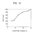
- the aforesaid problem is overcome by working a material while setting the ratio of change of the curvature to a value not greater than 10% of the final curvature, and setting the roll spacing to fall within the range specified by expression (1).
- This forming method may be applied to the final pass in the roll bending when no bend correcting work is executed.
- the bend correcting work may be executed in accordance with the method described above.
- Another alternative method is that, when the bend correcting work is executed subsequent to the tack welding, the above-described method is applied both to the final pass of the roll bending and the bend correcting work.
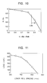
- Fig. 11 shows the results of a bend correcting work executed on a pipe blank, having a diameter of 500 mm and an end gap of about 50 mm, in which roll bending was effected after further changing the spacing L of the lower rolls for the purpose of correcting the curvature to achieve higher circularity.
- the lower limit of the lower roll spacing is set at a point where the load is reduced to zero, which corresponds to the pipe passing completely through the space between the lower rolls, as explained before in connection with Fig. 9B. It is therefore understood that the lower roll spacing L falling within the range specified by expression (1) is effective.
- a pipe blank which has already been shaped into the form of a pipe may be subjected again to roll bending which is executed with the lower roll spacing described above.
- the work process up to the completion of the blank pipe corresponds to intermediate passes in the pipe forming method of the invention, and the roll bending effected on the shaped pipe blank corresponds to the final pass of the pipe forming method of the invention.
- the use of the specified lower roll spacing during the roll bending on the completed pipe blank therefore, falls within the scope of the present invention.
- the load applied to the upper roll can be greatly reduced so that the deflection of the upper roll is suppressed correspondingly.
- This serves to suppress the creation of the end gap,even for pipes having diameters which are so small as to prevent the use of a backup beam or a large-diameter upper roll. It is thus possible to produce high-strength, thick-walled,elongated pipes of small diameters.
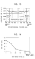
- Fig. 14 shows the results of an investigation in which the ratio of the end regions,bent in advance by other techniques (e.g. by a press) than the bending rolls,was varied in order to investigate how the size of the end gap varies in accordance with the ratio of the size of the end regions to the overall circumference of the pipe.
- the right-hand side of the diagram of Fig. 14, indicated by a value of 50% means that the circumferential length of each of the leading and trailing end regions bent in advance by, for example, a press, reaches 50% of the entire circumference of the pipe. That is, the entirety of the pipe has been finished by bending in advance the end bending method employing, for example, the press. Obviously, almost no end gap is formed in this state.
- each of the leading and trailing end regions of the sheet material be bent over a length which is at least 1/5 the entire circumference of the pipe.
- Such an end bending may be effected by a press as described above, or by rolls or other devices which can produce an effect to decrease the amount of the end gap to a level smaller than that produced by the bending rolls.
- the circumferential length of the regions to be bent by the bending rolls be restricted to be less than 3/5 the entire circumference of the pipe, in order that the end bent regions are not deformed or reduced in the course of the subsequent bending by the bending rolls.
- the operation of the bending rolls may be suspended to prevent the bent end regions from being affected by the bending rolls.
- the pipe forming method in accordance with the first to third aspects can be used not only for small-diameter pipes,but also for production of large-diameter pipes.
- the pipe forming method of the present invention when used in the production of large-diameter pipes, eliminates the necessity for any backup beam and alteration of the upper roll, thus contributing to simplification of the production equipment, and also to improvement in the efficiency of the pipe forming work.
- a symmetrical pyramidal three-roll-type roll bender having a pair of power-driven lower rolls and one tightening upper roll, has been specifically mentioned in the foregoing description.
- the use of this type of roll bender is not essential.
- the pipe forming method in accordance with the present invention may also be applied to a variety of types of roll benders, such as:an asymmetrical roll bender in which the upper roll is offset; a roll bender including more than 3 lower rolls, e.g. a four-roll type roll bender that has an additional lower roll arranged at a position spaced apart from the lower rolls 32 shown in Fig. 2; a pyramidal roll bender which is implemented by turning upside down the roll arrangement of Fig. 2; and a roll bender in which the pair of rolls and the counter roll are arranged laterally along the sheet material, rather than opposing each other across the sheet material.
- the pair of rolls may have different diameters, in which case the parameter Dwl used in the above expressions would be the sum of their radii Rw11 and Rw12.
- Figs. 16 and 17 are a front elevational view and a side elevational view, respectively, of a pipe forming apparatus embodying the present invention.
- the apparatus has a pair of lower rolls 32 and an upper roll 34 disposed above the lower rolls 32 at a position intermediate between the lower rolls.
- the pipe forming apparatus has a driving motor 50 for setting the lower roll spacing.
- the driving motor 50 is capable of setting the spacing L of the lower rolls 32 to a value greater than the sum of the diameter Dwu of the upper roll 34 and the diameter Dwl of one lower roll 32.
- the pipe forming apparatus also has a hydraulic drafting device 52 which can set the amount S of tightening of the upper roll 34 with respect to the lower roll 32 to a value which is greater than the radius Rwl of the lower roll 32.
- numeral 54 denotes a load cell for sensing the magnitude of the load acting on the upper roll 34
- 56 designates a lower-roll driving motor which drives the lower rolls 32 through a spindle 58.
- Figs. 18 to 20 show the relationships between the amount of tightening of the upper roll and the lower roll spacing, as observed when the tightening amount and roll spacing are varied in accordance with the progress of the passes,in accordance with the invention. More specifically, Fig. 18 shows the relationship as observed when the tightening by the upper roll is effected in earlier passes, while the lower roll spacing was varied in later passes. Fig. 19 shows the relationship as observed when the tightening by the upper roll and the change of the lower roll spacing were executed alternately. Fig. 20 shows the relationship as observed when the operation was executed in accordance with the graph shown in Fig. 11, in which the working condition was changed in a stepwise manner by releasing the upper roll, altering the lower roll spacing, and then resetting the upper roll to the original position.
- a high-tension steel sheet 30 mm thick and 6000 mm wide was cut into blank sheets of a length corresponding to the circumference of a pipe to be produced.
- the leading and trailing end regions of the blank sheets were pre-formed into arcuate form by a hydraulic press 42 of the type shown in Fig. 3.
- the thus-pre-worked steel sheets were then subjected to bending with a roll bender 30 in accordance with the present invention, so as to be formed into pipes of 500 mm and 700 mm diameter.
- the diameter Dwu of the upper roll and the diameter Dwl of the lower rolls were 400 mm and 350 mm, respectively.
- the pipe forming work using the roll bender 30 was executed in each of the following three conditions, (1) to (3).
- the lower roll spacing L was set to 600 mm.
- the lower roll spacing was set to 800 mm, while the amount S of tightening was less than 160 mm.
- Comparative Example 1 a large difference of 80 mm was observed between the end gap at the longitudinally central portion of the pipe and the end gap at both longitudinal ends of the pipe, due to excessive load applied during the pipe forming work, in each of the pipes of 700 mm and 500 mm diameter. Pipes having such large end gaps are not acceptable as commercial products.
- a high-tension steel sheet 40 mm thick and 6000 mm wide was cut into blank sheets of a length corresponding to the circumference of a pipe to be produced.
- the leading and trailing end regions of the blank sheets were pre-formed into arcuate form by a press.
- the thus-pre-worked steel sheets were then subjected to bending, conducted under three different conditions (1) to (3) as shown below with a roll bender, so as to be formed into pipes of 500 mm diameter.
- the diameter Dwu of the upper roll and the diameter Dwl of the lower rolls were 400 mm and 350 mm, respectively.
- the lower roll spacing L was set to 600 mm.
- the lower roll spacing was set to 1000 mm.
- Pipe forming work was conducted by employing tightening amounts S not-less than 180 mm, while the lower roll spacing L was initially set to 1000 mm and then progressively decreased.
- Comparative Example 3 as shown by a mark ⁇ , the first pass could not provide a desired amount of bend so that subsequent passes could not be executed and the pipe production failed.
- Comparative Example 4 as shown by a mark ⁇ , the desired amount of bend could be obtained in each pass by virtue of the reduction in the load offered by the lower roll spacing L being greater than that in Comparative Example 3.
- the lower roll spacing is not greater than 850 mm, pipe formation could not be executed because the pipe passed completely through the space between the lower rolls.
- Example 2 of the invention as indicated by a mark ⁇ , the desired amount of bend could be achieved in each of the earlier passes because the load magnitude was sufficiently low,as in Comparative Example 4.
- the pipe did not fully drop into the space between the lower rolls because the lower roll spacing L was reduced so that the pipe forming work could be continued down to the final diameter, while maintaining the load magnitude sufficiently low. Since the pipe forming work could be completed under a small load, the size of the end gap at the longitudinal center of the pipe was less than 10 mm, and hence a pipe having configuration acceptable as a commercial product could be obtained.
- steel pipes are specifically mentioned as the pipes to which the invention is applied. This, however, is only illustrative, and the invention may be applied equally well to the production of pipes of materials other than steel, e.g. copper, aluminum, titanium, brass and so forth.
- the mentioned hydraulic drafting device and driving motor are also illustrative, and various other actuators may be used for the purpose of tightening the upper roll and for changing the lower roll spacing.
- the lower rolls are power-driven while the upper roll is used as a tightening roll, this is not exclusive and other arrangements that produce an equivalent effect can also be adopted.
- a high-tension steel sheet 30 mm thick and 6000 mm wide was cut into blank sheets of a length corresponding to the circumference of a pipe to be produced.
- the leading and trailing end regions of the blank sheets were pre-formed into arcuate form by a hydraulic press 42 of the type shown in Fig. 3.
- the thus-pre-worked steel sheets were then subjected to bending with a roll bender 30, so as to be formed into pipes of 500 mm diameter, in accordance with the following two conditions, (1) and (2).
- the diameter Dwu of the upper roll and the diameter Dwl of the lower rolls were 400 mm and 350 mm, respectively.
- the lower roll spacing L was set to 600 mm.
- a high-tension steel sheet 30 mm thick and 6000 mm wide was cut into blank sheets of a length corresponding to the diameter of a pipe to be produced.
- the leading and trailing end regions of the blank sheets were pre-formed into arcuate form by a press.
- the thus-pre-worked steel sheets were then subjected to bending with a roll bender, so as to be formed into pipes of 500 nm diameter, under the following three conditions, (1) to (3).
- the diameter Dwu of the upper roll and the diameter Dwl of the lower rolls were 400 mm and 350 mm, respectively.
- the final pass was executed to effect a curvature change of 3 ⁇ 10 -4 (this amounts to a reduction of the diameter from 540 mm to 500 mm) while setting the lower roll spacing L to 800 mm.
- steel pipes are specifically mentioned as the pipes to which the invention is applied. This, however, is only illustrative,and the invention may be applied equally well to the production of pipes of materials other than steel, e.g. copper, aluminum, titanium, brass and so forth.
- the mentioned hydraulic drafting device and driving motor are also illustrative, and various other actuators may be used for the purpose of tightening the upper roll and for changing the lower roll spacing.
- the lower rolls are power-driven while the upper roll is used as a tightening roll, this is not exclusive, and other arrangements that produce an equivalent effect can also be adopted.
- a high-tension steel sheet 30 mm thick and 6000 mm wide was cut into blank sheets of a length corresponding to the diameter of a pipe to be produced.
- the leading and trailing end regions of the blank sheets were pre-formed into arcuate form by a hydraulic press 42 of the type shown in Fig. 3.
- the thus-pre-worked steel sheets were then subjected to bending with a roll bender 30 in accordance with the invention, so as to be formed into pipes of 500 mm diameter.
- the diameter Dwu of the upper roll and the diameter Dwl of the lower rolls were 400 mm and 350 mm, respectively.
- the pipe forming work was executed under the following three different conditions.
- the length of each end region bent by the press was set to be 1/6 the entire circumference of the pipe, and the pipe forming bending work was conducted while setting the lower roll spacing to 600 mm.
- each end region bent by the press was set to be 1/4 the entire circumference of the pipe, and the pipe forming bending work was conducted while setting the lower roll spacing to 600 mm and suspending the operation of the rolls such that the circumferential length of the region bent by the rolls is 1 ⁇ 2 the entire circumference of the pipe.
- each end region bent by the press was set to be 1/4 the entire circumference of the pipe, and the pipe forming bending work was conducted while setting the lower roll spacing to 800 mm and suspending the operation of the rolls such that the circumferential length of the region bent by the rolls is 1 ⁇ 2 the entire circumference of the pipe.
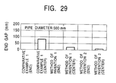
- the amounts of end gaps in the pipes produced under these different conditions are shown in Fig. 29 for comparison.
- the difference in the size of the end gap between the longitudinally central region and end regions was as large as 80 mm and hence the pipe was unacceptable as a commercial product. This is attributable to a too large load applied in the course of the bending.
- the difference in the size of the end gap between the longitudinal center and both longitudinal ends of the pipe was reduced to 20 mm, so that the pipe could be used as a product, although the load applied during the pipe forming work was not so small.
- the load applied during the pipe forming work was also reduced significantly, so that the difference in the size of the end opening between the longitudinal center and both longitudinal ends of the pipe was further reduced to 10 mm, thus providing an excellent pipe configuration.
- steel pipes are specifically mentioned as the pipes to which the invention is applied. This, however, is only illustrative,and the invention may be applied equally well to the production of pipes of materials other than steel, e.g. copper, aluminum, titanium, brass and so forth.
- the mentioned hydraulic drafting device and driving motor are also illustrative, and various other actuators may be used for the purpose of tightening the upper roll and for changing the lower roll spacing.
- the lower rolls are power-driven while the upper roll is used as a tightening roll, this is not exclusive,and other arrangements that produce an equivalent effect can also be adopted.
- the term "tightening" means the extent of lowering of the upper roll relative to the lower rolls, or more generally the extent to which the counter roll is made to approach the pair of bonding rolls during the pipe forming work.
Abstract
Description
- The present invention relates to a pipe forming apparatus which uses bending rolls, as well as to a pipe forming method and pipe formed by the apparatus or method. More particularly, the present invention relates to a pipe forming method which uses bending rolls including a pair of lower rolls arranged at one side of a sheet material and an upper roll arranged at the other side of the sheet material, intermediate between the pair of lower rolls, as well as to a pipe forming apparatus including the bending rolls and a pipe formed by the pipe forming apparatus or method. The pipe forming apparatus and method of the present invention are suitable for production of high-strength, thick-walled pipes.
- Mass production of pipes is generally carried out by using an electric welding mill when the pipe diameter is comparatively small, whereas UOE mills are used for pipes having comparatively large pipe diameters.
- For small-lot production, however, a method as shown in Fig. 1 is employed for pipes having large wall thicknesses. More specifically, referring to Fig. 1, a
blank sheet 10 is pressed between abending die 22 and a pressingdie 24 of aroll bender 20, and the pressing operation is repeated many times, e.g. 50 times or more, so as to bend the blank sheet into a pipe. In contrast, a method as illustrated in Fig. 2 is used when the wall thickness of the pipe is small. More specifically, referring to Fig. 2, apyramidal roll bender 30 employs three rolls: a pair oflower rolls 32 disposed under ablank sheet 10 and driven by a motor (not shown), and anupper roll 34 disposed on the upper side of theblank sheet 10 at a position intermediate between the pair oflower rolls 32. The tightening amount S, i.e. the extent to which theupper roll 34 is lowered, is adjustable. In operation, theblank sheet 10 is threaded between theupper roll 34 and thelower rolls 32 so as to be continuously bent at a curvature radius ρ. - A process of producing a pipe by the illustrated bending rolls is shown in Fig. 3. Firstly, cutting and groove work are conducted by means of a
flame planer 40 which cuts a blank sheet by using an oxygen or other gas plasma. Then, an end bending operation is performed by, for example, a hydraulic press for bending the end of the blank sheet that cannot be bent by bending rolls. Then, bending is effected by using, for example, apyramidal roll bender 30 having three rolls as shown in Fig. 2. Subsequently, an inner/outer surface welder 46 performs tack welding and welding of inner and outer surfaces. Then, end face milling is performed by an end face mill (not shown). The pipe thus formed is then shot-blasted in a shot-blast apparatus (not shown) and sent for testing and inspection. In some cases, bend correction is performed subsequent to roll bending or tack welding, in order to enhance the circularity of the pipe. Such bend correction is conducted substantially in the same way as the roll bending. - The production of pipes using bending rolls is suitable for multi-variety and small-quantity production, because it is adaptable to a variety of pipe diameters through adjustment of the amount S of tightening of the
upper roll 34. In addition, this type of pipe forming method is superior to methods using UOE mills, because of lower installation cost, and so forth. - On the other hand, this pipe forming method tends to allow an
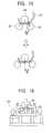
end gap 12A to occur in the center of the resultingpipe 12, as shown in Fig. 4, due to the difficulty of preventing deflection of the bending rolls, especially theupper roll 34. Therefore, this method is not suitable for use in the production of high-strength, thick-walled elongated pipe, which places a heavy load on the rolls and tends to cause deflection of the rolls. - This shortcoming arises because the
upper roll 34 is supported only at its opposite ends, and the outside diameter Dwu of theupper roll 34 is limited by the diameter of the product pipe such that the roll diameter must be smaller than the pipe diameter due to a geometrical requirement. On the other hand, deflection of the lower rolls is controllable because backup rolls may be placed in support of the lower rolls at suitable positions. - The pipe production method using a press bender is more suitable for the production of thick-walled pipes than the pipe-production method using a roll bender. However, it has a drawback in that the production efficiency is low due to the need for many pressing cycles, resulting in an elevated cost of production.
- Fig. 5 shows a pipe forming method which overcomes the above-described shortcoming of roll benders and which is disclosed in Japanese Kokai No. 53-128562. In this method, pressure is applied during the forming of a pipe to the
upper roll 34 from the upper side thereof by means of abackup beam 36 viabackup rolls 35. - Using this method, deflection of the
upper roll 34 is reduced so that the formation of the end gap is suppressed, thereby facilitating the production of high-strength, thick-walled, elongated pipes. - As an alternative measure, it is possible to use an upper roll of a greater diameter in accordance with an increase in the diameter of the pipe to be produced, thereby enabling production of high-strength, thick-walled, elongated pipes, by decreasing deflection of the upper roll.
- These known methods, however, are not suitable for use in the production of relatively small-diameter pipes, although they are effectively used in the production of large-diameter pipes. This is because there is insufficient space available between the
upper roll 34 and the inner surface of thepipe 12 for accommodating abackup beam 36 when the pipe diameter is relatively small, and a small-diameter upper roll thus must be used alone since, as stated before, the outside diameter Dwu of theupper roll 34 is limited by the inside diameter of the pipe to be produced. For these reasons, production of small-diameter pipes tends to be accompanied by the creation of an end gap, due to the lack of a technique for suppressing the deflection of the upper roll, such that the upper roll is often bent beyond an allowable limit. - Accordingly, it is desirable to improve the product pipe configuration by reducing the end gap, which tends to appear at a longitudinally central portion of the pipe, without causing the roll to be bent or deflected beyond an allowable limit.
- To this end, according to one aspect of the present invention, there is provided a pipe forming apparatus of the type using bending rolls including a plurality of rolls arranged on one side of a sheet material, and a counter roll arranged at the other side of the sheet material, comprising: a roll spacing setting device that sets the roll spacing of the pair of rolls to a range greater than the sum of the diameter of the counter roll and the diameter of one of the pair of rolls; and a device that sets the tightening amount of the counter roll relative to the pair of rolls to a range greater than the radius of one of the pair of rolls.
- The present invention enables forming the sheet material into a pipe with the pipe forming apparatus while setting the roll spacing between the pair of rolls to a value greater than the sum of the diameter of the counter roll and the diameter of each of the pair of rolls, and setting the amount of tightening to a value greater than the radius of each of the pair of rolls.
- The present invention in its second aspect provides a pipe forming method for forming a pipe using bending rolls including a plurality of rolls arranged on one side of a sheet material, and a counter roll arranged at the other side of the sheet material, the pipe forming method comprising: effecting pipe forming work on the sheet material such that the spacing L of the pair of rolls satisfies the following expression:
- The present invention in its third aspect provides a pipe forming method for forming a pipe using bending rolls including a plurality of rolls arranged on one side of a sheet material, and a counter roll arranged at the other side of the sheet material, the pipe forming method comprising: preparing the sheet material having leading and trailing bent end regions, bent beforehand over a length not smaller than 1/5 of the entire circumference of the pipe to be produced; and effecting roll bending such that the length of the regions bent by the bending rolls is less than 3/5 the entire circumference of the pipe to be produced.
- Reference will now be made, by way of example, to the accompanying drawings in which:
- Fig. 1 is a front elevational view of a conventional arrangement for producing a steel pipe with a press bender;
- Fig. 2 is a front elevational view of a known arrangement for producing a steel pipe with a roll bender;
- Fig. 3 is a perspective view of an arrangement for producing a steel pipe with a roll bender;
- Fig. 4 is a perspective view of a pipe produced by a known roll bender, showing particularly an end gap left in the pipe;
- Fig. 5 is a front elevational view of an arrangement which carries out a method proposed in Japanese Kokai No. 53-128562;
- Fig. 6 is a graph showing the relationship between the extent of lowering of an upper roll and the load acting on the upper roll, illustrating a principle of the present invention;
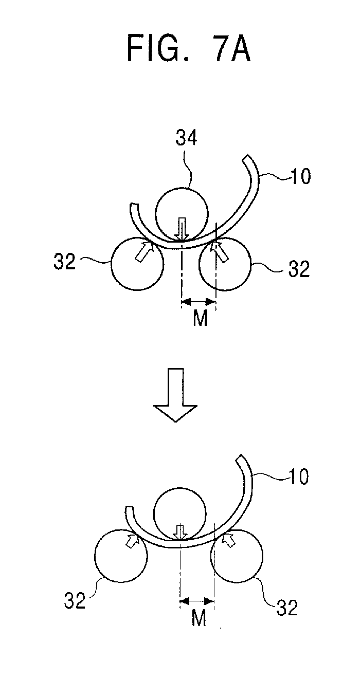
- Fig. 7A is a schematic illustration of an arrangement in which the spacing of the lower rolls has been increased;
- Fig. 7B is a schematic illustration of an arrangement in which an upper roll has been lowered while a large spacing is left between the lower rolls;
- Fig. 8 is a graph showing the relationship between the pipe diameter at the product pipe outlet and the load applied to the upper roll;
- Fig. 9A is a schematic illustration of an arrangement in which an upper roll has been lowered while a large spacing is left between the lower rolls;
- Fig. 9B is a schematic illustration of a product which is obtained when an excessively large spacing is left between the lower rolls;
- Fig. 10 is a graph showing the relationship between L = (Dp + Dwl) and a load ratio P/P0;
- Fig. 11 is a graph showing the relationship between the spacing of lower rolls and the load;
- Fig. 12 is a graph showing the relationship between the ratio of change in the curvature at the final pass and the load;
- Fig. 13 is a graph showing the results of an investigation conducted to find the variation in the severity of end gaps created at longitudinal central portions of product pipes along curvatures;
- Fig. 14 is a graph showing the results of the same investigation as that in Fig. 13 in which the ratio of the end bend has been changed;
- Fig. 15 is a schematic illustration of an arrangement having an increased lower roll spacing, explaining a principle of the present invention;
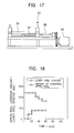
- Fig. 16 is a front elevational view of an embodiment of the pipe forming apparatus in accordance with the present invention;
- Fig. 17 is a side view of the pipe forming apparatus shown in Fig. 16;
- Fig. 18 is a graph showing an example of a procedure for changing the extent of lowering of the upper roll and the spacing of lower rolls in the pipe forming apparatus embodying the present invention;
- Fig. 19 is a dia showing another example of the procedure;
- Fig. 20 is a graph showing a further example of the procedure;
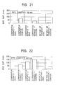
- Fig. 21 is a bar chart showing the amounts of end gaps of pipes having a pipe diameter of 700 mm produced in accordance with the method of the invention, in comparison with those of pipes produced in accordance with Comparison Examples;
- Fig. 22 is a bar chart showing the amounts of end gaps of pipes having a pipe diameter of 500 mm produced in accordance with the method of the invention, in comparison with those of pipes produced in accordance with Comparison Examples;
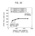
- Fig. 23 is a graph showing the relationship between the pipe diameter at the product pipe outlet and the load acting on the upper roll;
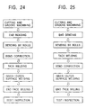
- Fig. 24 is a flow chart showing another example of a process for producing a steel pipe by using a roll bender;
- Fig. 25 is a flow chart showing a further example of the steel pipe production process;
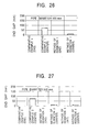
- Fig. 26 is a bar chart showing the amounts of end gaps of pipes having a pipe diameter of 500 mm produced in accordance with Examples of the method of the invention, in comparison with those of pipes produced in accordance with Comparison Examples;
- Fig. 27 is a diagram showing the amounts of end gaps of pipes having a pipe diameter of 500 mm produced in accordance with Examples of the method of the invention, in comparison with those of pipes produced in accordance with Comparison Examples;
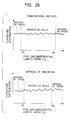
- Fig. 28 displays graphs of the curvature distribution of a pipe formed in accordance with an embodiment of the present invention, in comparison with that obtained with a pipe formed by a conventional method; and
- Fig. 29 is a bar chart showing the amounts of end gaps in pipes of 500 mm diameter produced in accordance with the method of the invention,in comparison with those of pipes produced in accordance with Comparative Examples.
-
- Fig. 6 shows the results of an investigation conducted on the apparatus of Fig. 2,having a pair of rolls serving as lower rolls and an upper roll serving as a counter roll, for the purpose of clarifying the relationship between the amount S of tightening, i.e. the extent of lowering of the upper roll and the load acting on the upper roll, as observed when the spacing L between the lower rolls is held constant. In this apparatus, the lower rolls 32 have a diameter Dwl of 350 mm, while the
upper roll 34 has a diameter Dwu of 400 mm. An open circle ○ shows data obtained when the spacing L of the lower rolls was set to a value (specifically 600 mm) which is smaller than the sum of the diameters of the upper and lower rolls (750mm), as in the conventional arrangements. When such a small spacing of the lower rolls is employed , high magnitudes of load are always observed. In contrast, solid circles indicate data obtained when the spacing L of the lower rolls was set to a value (specifically 800 mm) which is greater than the sum of the diameters of the upper and lower rolls (750 mm). With such a large spacing of the lower rolls, the magnitude of the load is generally maintained low. A further reduction in the load is achieved when the amount S of tightening, i.e. the extent of lowering of the upper roll, is increased beyond 175 mm,which is the radius Rwl of the lower roll, while the lower roll spacing L is maintained large. - The reason why the load is reduced when the
lower roll spacing 1 is increased will be explained with reference to Fig. 7A. When the lower roll spacing L is increased, the length of the bending moment M is correspondingly increased so that the load on the lower rolls is reduced and, at the same time, the load on the upper roll is reduced accordingly. - A description will now be given,with specific reference to Fig. 7B, as to why the load is further reduced in accordance with an increase in the amount S of tightening while the lower roll spacing L is large. In this case, the
upper roll 34 is lowered further into the region between the lower rolls 32 so that the direction of the loads acting on the lower rolls 32 are changed. In other words, although the magnitude of the load acting on the lower rolls is not reduced, the angle of action of the load is reduced, so that the load acting on the upper roll is reduced. - The angle of action of the load on the lower rolls is reduced, i.e., the upper roll is caused to penetrate more deeply into the region between the lower rolls, when the following conditions (1) and (2) are met:
- (1) In order that the
upper roll 34 is allowed to penetrate deeper into the region between the lower rolls 32, it is necessary that the lower roll spacing L be greater than the sum of the diameter Dwu of theupper roll 34 and the diameter Dwl of eachlower roll 32. - (2) Considering the situation in which the
upper roll 34 falls into the region between the lower rolls 32, it is necessary that the amount S of tightening, i.e. the extent of lowering of theupper roll 34, is greater than the radius Rwl of eachlower roll 32. -
- It is to be understood, however, that geometrical relationships exist between the amount S of tightening, i.e., the extent of lowering of the upper roll, the lower roll spacing L, and the diameter Dp of the
pipe 12 which is formed in contact with the upper andlower rolls - The load acting on the
upper roll 34 is remarkably reduced when conditions (1) and (2) are satisfied simultaneously, so that the deflection of theupper roll 34 is significantly reduced. Therefore, the tendency of leaving an end gap is suppressed,even for pipes whose diameters are so small that the backup beam and large-diameter upper rolls cannot be used. For instance, it becomes possible to produce high-strength, thick-walled, elongated pipes such as 20 mm or greater in thickness, 40 kgf/mm2 or higher in strength,and 5 m or longer in length. - In accordance with the present invention, it is especially preferred that the apparatus is operated such that not only is the spacing between adjacent rolls in a pair always maintained greater than the sum of the diameter of the counter roll and the diameter of one of the pair of rolls, but also that the roll spacing is progressively decreased as the pass progresses, so that the final amount of tightening is greater than the radius of the pair of rolls. Furthermore, in embodiments of the present invention, it is also especially preferred that the pipe forming apparatus be operated such that the upper roll is lowered to a predetermined level in excess of the radius of the pair of rolls in earlier passes of the process, whereas in later passes the roll spacing is reduced.
- Fig. 8 shows the relationship between the pipe diameter Dp and the load in each pass, as observed when a pipe is formed by bending roll apparatus while maintaining a constant spacing between lower rolls which serve as the pair of rolls. It will be seen that, when the lower roll spacing L is small, the load acting on the upper roll serving as the counter roll is greater for pipes having smaller diameters. In particular, the data marked by ○, obtained when the lower roll spacing L is 600 mm, indicates that the production of pipe is impossible. The Δ marks indicate data obtained when the lower roll spacing L has been increased to 800 mm. In this case, the load is reduced as compared with the case where the lower roll spacing is smaller. Furthermore, in this case the load is drastically reduced when the pipe diameter becomes smaller as a result of an increasing number of passes. The □ marks indicate data obtained when the lower roll spacing is increased to 1000 mm. In this case, it is impossible to form the pipe to the final diameter, although the load is reduced as the number of passes increases.
- In greater detail, during earlier passes in which the pipe diameter is still large, the length of the bending moment M for bending the sheet material is increased when the lower roll spacing L is increased, so that the load on the lower rolls and, hence, the load acting on the upper roll is reduced, as explained before in connection with Fig. 7A.
- In contrast, in later passes in which the pipe diameter has been reduced, an increase of the lower roll spacing L to a suitable value causes the
upper roll 34 to fall more deeply into the region between the lower rolls 32, hence the direction in which the load acts on the lower rolls is changed to decrease the load significantly. More specifically, although the magnitude of the load acting on the lower rolls is not decreased, the load acting on the roll is reduced owing to a reduction in the angle of action of the load. However, when the lower roll spacing L is increased excessively, thepipe 12 completely falls into the space between the lower rolls 32 so that the bending can no longer be effected. - The angle of action of the load on the lower rolls in the final stage of the process is decreased when the tightening amount S of the upper roll reaches a final value greater than the radius Rwl of the lower roll. That is, a geometrical relationship is established such that the upper roll falls down into the region between the lower rolls, thus making it possible to control the size of the end gap. This measure alone, however, cannot eliminate the risk of deflection of the upper roll beyond the allowable limit due to the heavy load that is applied in intermediate passes in which the above-described mechanism for reducing the load does not function.
- However, until the number of passes reaches such intermediate passes, the falling down of the pipe completely into the region between the lower rolls does not occur,even if the lower roll spacing L is set large, because the diameter of the pipe is still large enough to prevent such falling of the pipe. It is therefore possible to maintain the load sufficiently low so as to avoid excessive deflection of the upper roll by operating such that: in earlier passes in which the pipe diameter is still large the lower roll spacing L is set large so as to reduce the magnitude of the load; whereas in later passes the lower roll spacing L is progressively reduced as the pipe forming work proceeds towards the final pass in order to decrease the angle of action of the load on the lower rolls.
- More specifically, the lower roll spacing L and the amount S of tightening in each pass may be set as follows.
- As the first step, the lower roll spacing L is set to the maximum possible value. During earlier passes, the
upper roll 34 is progressively lowered to increase the amount S of tightening in accordance with the increasing number of passes, while maintaining the above-mentioned maximum possible lower roll spacing L. Consequently, the pipe diameter is progressively decreased until the tightening amount S reaches the final value. This final value is greater than the lower roll radius Rwl in order that the upper roll enters the region between the lower rolls. In later passes, the work is performed by progressively reducing the lower roll spacing L, while maintaining the above-mentioned final value of tightening S, thereby further decreasing the pipe diameter and thus completing the forming of the pipe. - With this pipe forming method, it is possible to always maintain the load at sufficiently low magnitudes by a combined load reducing effect offered by the large lower roll spacing L in earlier passes, and the reduction in the angle of action of the load offered in later passes of the pipe forming work.
- Thus, pipes can be formed without causing the load on the upper roll to exceed the maximum allowable value, while preventing the creation of an end gap, even when the pipe diameter is so small as to preclude the use of a backup beam or a large-diameter upper roll. It is thus possible to produce high-strength, thick-walled, elongated pipes.
- As explained before in connection with Fig. 8,which shows the relationship between the pipe diameter Dp and the load in each pass, the production of a pipe is impossible when the lower roll spacing L is 600 mm, as indicated by the mark ○. When the lower roll spacing L is increased to 800 mm, the load is reduced compared with the case where the lower roll spacing L is smaller, as indicated by the mark Δ. A further increase of the lower roll spacing L to 1000 mm makes it impossible to work the pipe to the final diameter, although the magnitude of the load in intermediate passes is lowered, as indicated by the mark □.
- Figs. 9A and 9B show the roll arrangement for a given final pipe diameter. As will be seen from Fig. 9A, when the lower roll spacing L is increased to a suitable value, the
upper roll 34 is allowed to fall into the region between the lower rolls 32, with the result that the direction of the load on the lower rolls is changed to significantly reduce the load. More specifically, the angle of action of the load is decreased,although the magnitude of the load acting on the lower rolls 32 is not changed, so that the magnitude of the load acting on the upper roll is reduced. When the lower roll spacing L is increased excessively, thepipe 12 completely falls into the region between the lower rolls 32, thus making it impossible to effect further work for forming the pipe. - In other words, it is possible to significantly reduce the load, on condition that the lower roll spacing L is set to a value which is large but does not exceed a value that allows the pipe to fully fall into the region between the rolls. The size of the end gap depends on the final forming condition. It suffices that the above-mentioned condition concerning the lower roll spacing be met in the final stage. For a product pipe diameter Dp, a lower roll diameter Dwl, and a lower roll spacing L, the geometrical threshold condition for preventing the pipe from fully falling down into the region between the lower rolls is given by the following expression :
- It is therefore understood that the lower roll spacing L has to be smaller than the sum (Dp + Dwl) of the product pipe outside diameter Dp and the lower roll diameter Dwl in order to avoid complete falling of the pipe into the space between the lower rolls. However, the lower limit of the lower roll spacing L is still unknown. An investigation was therefore made to find the relationship between the ratio L/(Dp + Dwl) (i.e., ratio of spacing L to the sum (Dp + Dwl) of the product pipe outside diameter Dp and the lower roll diameter Dwl) and the load (P/P0), the result of which is shown in Fig. 10. The symbol P0 represents the magnitude of the load as obtained when the lower roll spacing L is set to L = 0.5(Dp + Dwl). As will be seen from this Figure, the load drastically decreases when the ratio L/(Dp + Dwl) exceeds 0.85,and is reduced to zero when the ratio L/(Dp + Dwl) reaches 1.0. This reveals the threshold condition. It is thus demonstrated that the range specified by expression (1) is the effective range.
- Therefore, the load can be maintained sufficiently low when the pipe forming work is executed by progressively increasing the amount S of tightening,while setting the lower roll spacing L to fall within the range specified by expression (1). Consequently, it is possible to form a high-strength, thick-walled, elongated pipe with a reduced end gap, even when the pipe diameter is so small as to exclude the use of a backup beam or a large-diameter upper roll.
- In order that the lower roll spacing is set to fall within the range specified by expression (1), it is advantageous that the
lower roll spacing 1 is linearly variable. This, however, is not essential and the change in the lower roll spacing may be effected in a stepwise manner over several stages by changing the roll combination. It is also to be understood that the pipe forming apparatus of the present invention may employ lower rolls that are set at a fixed spacing L. In other words, the condition of expression (1) is met for pipes with diameters that fall within a certain range, and the production of such pipes, while satisfying the condition of expression (1), falls within the scope of the present invention. - In accordance with the present invention, the aforesaid problem is overcome by working a material while setting the ratio of change of the curvature to a value not greater than 10% of the final curvature, and setting the roll spacing to fall within the range specified by expression (1).
- This forming method may be applied to the final pass in the roll bending when no bend correcting work is executed. Alternatively, when bend correction is effected prior to tack welding, the bend correcting work may be executed in accordance with the method described above.
- Another alternative method is that, when the bend correcting work is executed subsequent to the tack welding, the above-described method is applied both to the final pass of the roll bending and the bend correcting work.
- Fig. 11 shows the results of a bend correcting work executed on a pipe blank, having a diameter of 500 mm and an end gap of about 50 mm, in which roll bending was effected after further changing the spacing L of the lower rolls for the purpose of correcting the curvature to achieve higher circularity. It will be seen that the load is reduced in two stages in accordance with the increase in the lower roll spacing. As a result, the size of the end gap is also changed drastically. The lower limit of the lower roll spacing is set at a point where the load is reduced to zero, which corresponds to the pipe passing completely through the space between the lower rolls, as explained before in connection with Fig. 9B. It is therefore understood that the lower roll spacing L falling within the range specified by expression (1) is effective. More specifically, it is possible to maintain the load sufficiently low when the pipe forming work is executed by progressively increasing the tightening amount of the upper roll,while maintaining the lower roll spacing L within the range specified by expression (1). This indicates that the size of the end gap is determined solely by the final pass, regardless of the intermediate passes.
- The above-described results, however, are obtained when a pipe blank that has already been formed into the shape of a pipe is again worked for correction of its curvature. An experiment was therefore executed in which the magnitude of the load and the size of the end gap were examined with various curvatures in the final pass, while setting the lower roll spacing of the final pass to fall within the above-described range. The results of the experiment are shown in Fig. 12. It can be seen from Fig. 12 that the load drastically drops when the bending curvature is not greater than 10% of the pipe curvature. It is therefore understood that the final pass should be executed to effect bending as small as that for a bend correcting pass. As described above, a pipe blank which has already been shaped into the form of a pipe may be subjected again to roll bending which is executed with the lower roll spacing described above. In such a case, the work process up to the completion of the blank pipe corresponds to intermediate passes in the pipe forming method of the invention, and the roll bending effected on the shaped pipe blank corresponds to the final pass of the pipe forming method of the invention. The use of the specified lower roll spacing during the roll bending on the completed pipe blank, therefore, falls within the scope of the present invention.
- When the above-described conditions are satisfied, the load applied to the upper roll can be greatly reduced so that the deflection of the upper roll is suppressed correspondingly. This serves to suppress the creation of the end gap,even for pipes having diameters which are so small as to prevent the use of a backup beam or a large-diameter upper roll. It is thus possible to produce high-strength, thick-walled,elongated pipes of small diameters.
- The inventors have made an investigation to find the curvature distribution of the end gap created in the longitudinally central region of the pipe. As will be understood from Fig. 13,which shows the results of the investigation, the leading and trailing end regions of the pipe that are not worked by the bending rolls, i.e. that are bent in advance of the process by means of a press or the like, are finished so as to have a curvature of 0.004, which corresponds to the diameter of the product pipe, whereas the intermediate portions that have been bent by means of the bending rolls have smaller curvatures. This indicates that the creation of the end gap is attributable to insufficient roll bending of the intermediate portions.
- Fig. 14 shows the results of an investigation in which the ratio of the end regions,bent in advance by other techniques (e.g. by a press) than the bending rolls,was varied in order to investigate how the size of the end gap varies in accordance with the ratio of the size of the end regions to the overall circumference of the pipe. The right-hand side of the diagram of Fig. 14, indicated by a value of 50%, means that the circumferential length of each of the leading and trailing end regions bent in advance by, for example, a press, reaches 50% of the entire circumference of the pipe. That is, the entirety of the pipe has been finished by bending in advance the end bending method employing, for example, the press. Obviously, almost no end gap is formed in this state. This state, however, is an extreme one, and a significant decrease in the size of the end gap is achieved when the circumferential length of each end region that is bent in advance of the roll bending is 20% i.e. one fifth of the entire circumference of the pipe. This results from the fact that the tendency for the roll bending to become insufficient is suppressed by the effect produced by the rigidity of the end regions, which have been bent in advance of the bending by the bending rolls.
- In order that the end bent region is enlarged to reach 1/5 the entire circumference of the pipe, it is necessary that each of the leading and trailing end regions of the sheet material be bent over a length which is at least 1/5 the entire circumference of the pipe. Such an end bending may be effected by a press as described above, or by rolls or other devices which can produce an effect to decrease the amount of the end gap to a level smaller than that produced by the bending rolls.
- Furthermore, it is necessary that the circumferential length of the regions to be bent by the bending rolls be restricted to be less than 3/5 the entire circumference of the pipe, in order that the end bent regions are not deformed or reduced in the course of the subsequent bending by the bending rolls. In order to avoid the undesirable deformation of the end bent regions, the operation of the bending rolls may be suspended to prevent the bent end regions from being affected by the bending rolls.
- An increase in the spacing L of the lower rolls, serving as the pair of rolls (see Fig. 2),not only increases the circumferential length of the zone in each bent end region not affected by the bending rolls, but also serves to reduce the deflection of the rolls. More specifically, an increase in the lower roll spacing L naturally increases the distance between each
lower roll 32 and theupper roll 34 serving as the counter roll, so that the circumferential length of the zone not affected by the bending rolls is increased. Further, as will be seen from Fig. 15, the increase in the distance between theupper roll 34 and thelower roll 32 leads to an increase in the length of the arm of the bending moment M, so that the load is reduced correspondingly to suppress the bending of the rolls. Thus, when the circumferential length of the region to be bent by the rolls is set below 3/5 of the entire circumference of the pipe and the lower roll spacing L is increased, a greater effect of suppressing the creation of an end gap is achieved because the bending by the rolls themselves contributes to prevent the formation of the end gap, by virtue of the reduced deflection of the rolls. It is also possible to simultaneously use both the suspension of the bending roll operation and the increase of the lower roll spacing L when setting the circumferential length of the region to be bent by the rolls to less than 3/5 of the entire circumference of the pipe. - According to this aspect of the present invention, it is possible to produce high-strength, thick-walled,elongated pipes, even when the pipe diameters are so small as to prevent the use of a backup beam or a large-diameter upper roll.
- It will be clear to those skilled in the art that the pipe forming method in accordance with the first to third aspects can be used not only for small-diameter pipes,but also for production of large-diameter pipes. The pipe forming method of the present invention, when used in the production of large-diameter pipes, eliminates the necessity for any backup beam and alteration of the upper roll, thus contributing to simplification of the production equipment, and also to improvement in the efficiency of the pipe forming work.
- A symmetrical pyramidal three-roll-type roll bender, having a pair of power-driven lower rolls and one tightening upper roll, has been specifically mentioned in the foregoing description. The use of this type of roll bender, however, is not essential. For instance, the pipe forming method in accordance with the present invention may also be applied to a variety of types of roll benders, such as:an asymmetrical roll bender in which the upper roll is offset; a roll bender including more than 3 lower rolls, e.g. a four-roll type roll bender that has an additional lower roll arranged at a position spaced apart from the lower rolls 32 shown in Fig. 2; a pyramidal roll bender which is implemented by turning upside down the roll arrangement of Fig. 2; and a roll bender in which the pair of rolls and the counter roll are arranged laterally along the sheet material, rather than opposing each other across the sheet material.
- It is also to be noted that the pair of rolls may have different diameters, in which case the parameter Dwl used in the above expressions would be the sum of their radii Rw11 and Rw12.
- The embodiment of each aspect of the invention will now be illustrated through Examples.
- Figs. 16 and 17 are a front elevational view and a side elevational view, respectively, of a pipe forming apparatus embodying the present invention. The apparatus has a pair of
lower rolls 32 and anupper roll 34 disposed above the lower rolls 32 at a position intermediate between the lower rolls. Additionally, the pipe forming apparatus has a drivingmotor 50 for setting the lower roll spacing. The drivingmotor 50 is capable of setting the spacing L of the lower rolls 32 to a value greater than the sum of the diameter Dwu of theupper roll 34 and the diameter Dwl of onelower roll 32. The pipe forming apparatus also has ahydraulic drafting device 52 which can set the amount S of tightening of theupper roll 34 with respect to thelower roll 32 to a value which is greater than the radius Rwl of thelower roll 32. In Figs. 16 and 17, numeral 54 denotes a load cell for sensing the magnitude of the load acting on theupper roll 34, while 56 designates a lower-roll driving motor which drives the lower rolls 32 through aspindle 58. - Figs. 18 to 20 show the relationships between the amount of tightening of the upper roll and the lower roll spacing, as observed when the tightening amount and roll spacing are varied in accordance with the progress of the passes,in accordance with the invention. More specifically, Fig. 18 shows the relationship as observed when the tightening by the upper roll is effected in earlier passes, while the lower roll spacing was varied in later passes. Fig. 19 shows the relationship as observed when the tightening by the upper roll and the change of the lower roll spacing were executed alternately. Fig. 20 shows the relationship as observed when the operation was executed in accordance with the graph shown in Fig. 11, in which the working condition was changed in a stepwise manner by releasing the upper roll, altering the lower roll spacing, and then resetting the upper roll to the original position.
- A high-
tension steel sheet 30 mm thick and 6000 mm wide was cut into blank sheets of a length corresponding to the circumference of a pipe to be produced. The leading and trailing end regions of the blank sheets were pre-formed into arcuate form by ahydraulic press 42 of the type shown in Fig. 3. The thus-pre-worked steel sheets were then subjected to bending with aroll bender 30 in accordance with the present invention, so as to be formed into pipes of 500 mm and 700 mm diameter. The diameter Dwu of the upper roll and the diameter Dwl of the lower rolls were 400 mm and 350 mm, respectively. - The pipe forming work using the
roll bender 30 was executed in each of the following three conditions, (1) to (3). - The lower roll spacing L was set to 600 mm.
- The lower roll spacing was set to 800 mm, while the amount S of tightening was less than 160 mm.
- Pipe forming work was conducted by employing tightening amounts S not smaller than 180 mm, while the lower roll spacing L was varied within the range from 800 to 1200 mm. The sizes of the end gaps observed after the pipe forming work under these three different conditions are shown in Fig. 21 for the pipes of 700 mm diameter,and in Fig. 22 for the pipes of 500 mm diameter.
- In Comparative Example 1, a large difference of 80 mm was observed between the end gap at the longitudinally central portion of the pipe and the end gap at both longitudinal ends of the pipe, due to excessive load applied during the pipe forming work, in each of the pipes of 700 mm and 500 mm diameter. Pipes having such large end gaps are not acceptable as commercial products.
- In Comparative Example 2, the pipe of 700 mm diameter showed a reduced difference of 40 mm between the end gap at the longitudinal center and the longitudinal end of the pipe, owing to the reduction in the load magnitude offered by the spacing L between the lower rolls being greater than that in Comparative Example 1. The pipe thus formed, however, is still unsatisfactory due to its inferior final pipe configuration. In the case of the 500 mm diameter pipe, a large end gap in excess of 100 mm was formed both at the longitudinal center and end portions of the pipe. Therefore, this pipe was completely useless as a commercial product. This is attributable to an insufficient tightening amount S of 160 mm.
- Referring now to Inventive Example 1, sufficiently large amounts S of tightening were afforded by virtue of the appropriate setting of the lower roll spacing L, so that the pipe forming work could be conducted under significantly reduced load for both pipes of 500 mm and 700 mm diameter. Consequently, the sizes of the end gaps at the longitudinal centers of the pipes were as small as under 10 mm, so that pipes having configurations acceptable as commercial products could be obtained.
- A high-
tension steel sheet 40 mm thick and 6000 mm wide was cut into blank sheets of a length corresponding to the circumference of a pipe to be produced. The leading and trailing end regions of the blank sheets were pre-formed into arcuate form by a press. The thus-pre-worked steel sheets were then subjected to bending, conducted under three different conditions (1) to (3) as shown below with a roll bender, so as to be formed into pipes of 500 mm diameter. The diameter Dwu of the upper roll and the diameter Dwl of the lower rolls were 400 mm and 350 mm, respectively. - The lower roll spacing L was set to 600 mm.
- The lower roll spacing was set to 1000 mm.
- Pipe forming work was conducted by employing tightening amounts S not-less than 180 mm, while the lower roll spacing L was initially set to 1000 mm and then progressively decreased.
- Load magnitudes for the respective passes are shown in Fig. 23.
- In Comparative Example 3, as shown by a mark ○, the first pass could not provide a desired amount of bend so that subsequent passes could not be executed and the pipe production failed. In Comparative Example 4, as shown by a mark □, the desired amount of bend could be obtained in each pass by virtue of the reduction in the load offered by the lower roll spacing L being greater than that in Comparative Example 3. However, when the lower roll spacing is not greater than 850 mm, pipe formation could not be executed because the pipe passed completely through the space between the lower rolls. In contrast, in Example 2 of the invention, as indicated by a mark ▪, the desired amount of bend could be achieved in each of the earlier passes because the load magnitude was sufficiently low,as in Comparative Example 4. In later passes, the pipe did not fully drop into the space between the lower rolls because the lower roll spacing L was reduced so that the pipe forming work could be continued down to the final diameter, while maintaining the load magnitude sufficiently low. Since the pipe forming work could be completed under a small load, the size of the end gap at the longitudinal center of the pipe was less than 10 mm, and hence a pipe having configuration acceptable as a commercial product could be obtained.
- In the foregoing description, steel pipes are specifically mentioned as the pipes to which the invention is applied. This, however, is only illustrative, and the invention may be applied equally well to the production of pipes of materials other than steel, e.g. copper, aluminum, titanium, brass and so forth.
- The mentioned hydraulic drafting device and driving motor are also illustrative, and various other actuators may be used for the purpose of tightening the upper roll and for changing the lower roll spacing. Furthermore, although the lower rolls are power-driven while the upper roll is used as a tightening roll, this is not exclusive and other arrangements that produce an equivalent effect can also be adopted.
- According to embodiments of the present invention, it is possible to suppress the deflection of the counter roll by reducing the magnitude of the load applied to the upper roll during the bending work performed by the roll bender. Consequently, the bending work is performed without causing the deflection of the upper roll to exceed the allowable limit, so that the creation of the end gap at the longitudinally central region of the pipe is sufficiently suppressed. It is therefore possible to produce high-strength, thick-walled,elongated pipes having an excellent pipe configuration and a high degree of dimensional precision.
- A high-
tension steel sheet 30 mm thick and 6000 mm wide was cut into blank sheets of a length corresponding to the circumference of a pipe to be produced. The leading and trailing end regions of the blank sheets were pre-formed into arcuate form by ahydraulic press 42 of the type shown in Fig. 3. The thus-pre-worked steel sheets were then subjected to bending with aroll bender 30, so as to be formed into pipes of 500 mm diameter, in accordance with the following two conditions, (1) and (2). The diameter Dwu of the upper roll and the diameter Dwl of the lower rolls were 400 mm and 350 mm, respectively. - The lower roll spacing L was set to 600 mm.
- All the passes were executed while setting the lower roll spacing L to 800 mm. The amounts of end gaps obtained under these two different conditions are shown in Fig. 26.
- In Comparative Example 1, the difference in the size of the end gap between the longitudinally central region and end regions was as large as 80 mm and hence the pipe was unacceptable as a commercial product. This is attributable to a too large load applied in the course of the bending. In contrast, in Inventive Example 1, the magnitude of the load could be significantly reduced by virtue of the large amount S of tightening. Consequently, the pipe had only a small end gap of 10 mm at the longitudinal center. It was thus possible to obtain a product pipe having an excellent pipe configuration.
- A high-
tension steel sheet 30 mm thick and 6000 mm wide was cut into blank sheets of a length corresponding to the diameter of a pipe to be produced. The leading and trailing end regions of the blank sheets were pre-formed into arcuate form by a press. The thus-pre-worked steel sheets were then subjected to bending with a roll bender, so as to be formed into pipes of 500 nm diameter, under the following three conditions, (1) to (3). The diameter Dwu of the upper roll and the diameter Dwl of the lower rolls were 400 mm and 350 mm, respectively. - All the passes were executed while the lower roll spacing L was set to 600 mm.
- The final pass was executed to effect a curvature change of 3 × 10⁻⁴ (this amounts to a reduction of the diameter from 540 mm to 500 mm) while setting the lower roll spacing L to 800 mm.
- A pipe which was formed in accordance with Comparative Example 1 was again subjected to bending,executed with the lower roll spacing L set to L = 800 mm.
- The sizes of the end gaps in the pipes produced under these conditions are shown in Fig. 27 for comparison.
- In Comparative Example 2, the difference in the size of the end gap between the longitudinally central region and end regions was as large as 80 mm and hence the pipe was unacceptable as a commercial product. This is attributable to a too large load applied in the course of the bending. In contrast, in each of Inventive Examples 2 and 3, the magnitude of the load could be significantly reduced by virtue of the large amount S of tightening. Consequently, the pipe had only a small end gap of 10 mm at the longitudinal center. It was thus possible to obtain a product pipe having an excellent pipe configuration.
- In the foregoing description, steel pipes are specifically mentioned as the pipes to which the invention is applied. This, however, is only illustrative,and the invention may be applied equally well to the production of pipes of materials other than steel, e.g. copper, aluminum, titanium, brass and so forth.
- The mentioned hydraulic drafting device and driving motor are also illustrative, and various other actuators may be used for the purpose of tightening the upper roll and for changing the lower roll spacing. Furthermore, although the lower rolls are power-driven while the upper roll is used as a tightening roll, this is not exclusive, and other arrangements that produce an equivalent effect can also be adopted.
- Thus, in accordance with the present invention, it is possible to reduce the load applied to the counter roll during pipe forming work performed by bending rolls, thus suppressing the deflection of the counter roll in a pass which may be the final pass. It is therefore possible to suppress the creation of an end gap at the longitudinally central region of the pipe, thus enabling the production of high-strength, thick-walled,elongated pipes having excellent pipe configurations.
- The curvature distribution of the pipe formed in accordance with an embodiment of the invention is shown in Fig. 28, together with that obtained with a conventional, included for the purpose of comparison.
- A high-
tension steel sheet 30 mm thick and 6000 mm wide was cut into blank sheets of a length corresponding to the diameter of a pipe to be produced. The leading and trailing end regions of the blank sheets were pre-formed into arcuate form by ahydraulic press 42 of the type shown in Fig. 3. The thus-pre-worked steel sheets were then subjected to bending with aroll bender 30 in accordance with the invention, so as to be formed into pipes of 500 mm diameter. The diameter Dwu of the upper roll and the diameter Dwl of the lower rolls were 400 mm and 350 mm, respectively. The pipe forming work was executed under the following three different conditions. - The length of each end region bent by the press was set to be 1/6 the entire circumference of the pipe, and the pipe forming bending work was conducted while setting the lower roll spacing to 600 mm.
- The length of each end region bent by the press was set to be 1/4 the entire circumference of the pipe, and the pipe forming bending work was conducted while setting the lower roll spacing to 600 mm and suspending the operation of the rolls such that the circumferential length of the region bent by the rolls is ½ the entire circumference of the pipe.
- The length of each end region bent by the press was set to be 1/4 the entire circumference of the pipe, and the pipe forming bending work was conducted while setting the lower roll spacing to 800 mm and suspending the operation of the rolls such that the circumferential length of the region bent by the rolls is ½ the entire circumference of the pipe. The amounts of end gaps in the pipes produced under these different conditions are shown in Fig. 29 for comparison.
- In the Comparative Example, the difference in the size of the end gap between the longitudinally central region and end regions was as large as 80 mm and hence the pipe was unacceptable as a commercial product. This is attributable to a too large load applied in the course of the bending. In Inventive Example 1, the difference in the size of the end gap between the longitudinal center and both longitudinal ends of the pipe was reduced to 20 mm, so that the pipe could be used as a product, although the load applied during the pipe forming work was not so small. In Inventive Example 2, the load applied during the pipe forming work was also reduced significantly, so that the difference in the size of the end opening between the longitudinal center and both longitudinal ends of the pipe was further reduced to 10 mm, thus providing an excellent pipe configuration.
- In the foregoing description, steel pipes are specifically mentioned as the pipes to which the invention is applied. This, however, is only illustrative,and the invention may be applied equally well to the production of pipes of materials other than steel, e.g. copper, aluminum, titanium, brass and so forth.
- The mentioned hydraulic drafting device and driving motor are also illustrative, and various other actuators may be used for the purpose of tightening the upper roll and for changing the lower roll spacing. Furthermore, although the lower rolls are power-driven while the upper roll is used as a tightening roll, this is not exclusive,and other arrangements that produce an equivalent effect can also be adopted.
- Thus, in embodiments of the present invention, it is possible to reduce the load applied to the rolls during pipe forming work by virtue of the rigidity exhibited by the bent end regions that have been bent by, for example, the press. It is therefore possible to suppress the creation of an end gap at the longitudinally central region of the pipe, thus enabling the production of high-strength, thick-walled, elongated pipes having excellent pipe configurations.
- In the following claims, the term "tightening" means the extent of lowering of the upper roll relative to the lower rolls, or more generally the extent to which the counter roll is made to approach the pair of bonding rolls during the pipe forming work.
Claims (15)
- A pipe forming apparatus comprising at least a pair of bending rolls arranged to work one side of a sheet of feed material, and a counter roll arranged to work the other side of said sheet, said apparatus further comprising:a roll spacing setting device adapted to set the roll spacing of the pair of rolls to a value greater than the sum of the diameter of said counter roll and the diameter of one of said pair of rolls; anda tightening amount setting device adapted to set the amount of tightening of said counter roll relative to said pair of rolls to a value greater than the radius of one of said pair of rolls.
- A pipe forming method for forming a pipe by roll bending, comprising the steps of:
forming a sheet of feed material into a pipe using a pipe forming apparatus according to claim 1, while setting the roll spacing between said pair of rolls to a value greater than the sum of the diameter of said counter roll and the diameter of one of said pair of rolls, and setting the amount of tightening to a value greater than the radius of one of said pair of rolls. - A pipe forming method for forming a pipe by means of bending rolls, comprising the steps of:
forming a sheet of feed material into a pipe using the pipe forming apparatus according to claim 1, while maintaining the roll spacing between said pair of rolls greater than the sum of the diameter of said counter roll and the diameter of one of said pair of rolls, and progressively reducing the roll spacing in accordance with the number of passes so as to enable the amount of tightening to be finally set to a value greater than the radius of one of said pair of rolls. - A pipe forming method according to Claim 3,
wherein, in earlier passes, the amount of tightening is increased to a predetermined value greater than the radius of one of the plural rolls, whereas, in later passes, the roll spacing is progressively decreased, thereby forming said sheet material into a pipe. - A pipe forming method for forming a pipe using a pipe forming apparatus of the type having bending rolls including a pair of rolls arranged on one side of a sheet material, and a counter roll arranged at the other side of the sheet material, said pipe forming method comprising:effecting pipe forming work on said sheet material such that the spacing L of the pair of rolls satisfies the following expression:wherein Dp represents the outside diameter of the product pipe and Dwl represents the diameter of one of the pair of rolls.
- A pipe forming method according to Claim 5,
further comprising the steps of effecting correction of the bend by effecting roll bending to provide a curvature change which is not greater than 10% of the final curvature. - A pipe forming method, wherein, when no bend correcting work is executed, the forming method of Claim 6 is applied to the final pass of the bending by the bending rolls.
- A pipe forming method, wherein, when bend correcting work is executed subsequent to a tack welding, the forming method of Claim 6 is applied to said bend correcting work.
- A pipe forming method, wherein, when bend correcting work is executed subsequent to a tack welding, the forming method of Claim 6 is applied to the final pass of the bending by the bending rolls and to said bend correcting work.
- A pipe forming method for forming a pipe using a pipe forming apparatus of the type using bending rolls including a plurality of rolls arranged on one side of a sheet material, and a counter roll arranged at the other side of the sheet material, said pipe forming method comprising:providing a sheet of feed material having leading and trailing bent end regions,each bent beforehand over a length not smaller than 1/5 of the entire circumference of the pipe to be produced; andeffecting roll bending such that the length of the regions bent by the bending rolls is less than 3/5 the entire circumference of the pipe to be produced.
- A pipe forming method according to Claim 10,
wherein operation of the bending rolls is suspended during passage of each of said bent end regions so as to avoid deformation of the bent end regions by the bending rolls, thereby ensuring that the length of the region bent by the bending rolls is less than 3/5 the entire circumference of the pipe to be produced. - A pipe forming method according to Claim 10,
wherein the roll spacing of said plural rolls is increased, thereby ensuring that the length of the region bent by the bending rolls is less than 3/5 the entire circumference of the pipe to be produced. - A pipe forming apparatus comprising a plurality of bending rolls arranged to work one side of a sheet of feed material, and a counter roll arranged to work the other side of said sheet at an intermediate position between a pair of the plurality of rolls, said apparatus further comprising:roll spacing setting means for setting the roll spacing of the pair of rolls to a value greater than the sum of the diameter of said counter roll and the diameter of one of said pair of rolls; andtightening amount setting means for setting the amount of tightening of said counter roll relative to said pair of rolls to a value greater than the radius of one of said pair of rolls.
- A pipe formed by the apparatus of claim 1 or 13.
- A pipe formed by the method of any of claims 2 to 12.
Priority Applications (1)
| Application Number | Priority Date | Filing Date | Title |
|---|---|---|---|
| EP04024790A EP1514619A3 (en) | 1998-11-04 | 1999-11-04 | Pipe forming method and apparatus |
Applications Claiming Priority (6)
| Application Number | Priority Date | Filing Date | Title |
|---|---|---|---|
| JP31320698A JP3332216B2 (en) | 1998-11-04 | 1998-11-04 | Pipe forming apparatus and forming method using bending roll |
| JP31320798 | 1998-11-04 | ||
| JP31320898A JP3332217B2 (en) | 1998-11-04 | 1998-11-04 | Pipe forming method with bending roll |
| JP31320898 | 1998-11-04 | ||
| JP31320698 | 1998-11-04 | ||
| JP31320798A JP3358654B2 (en) | 1998-11-04 | 1998-11-04 | Pipe forming method with bending roll |
Related Child Applications (1)
| Application Number | Title | Priority Date | Filing Date |
|---|---|---|---|
| EP04024790A Division EP1514619A3 (en) | 1998-11-04 | 1999-11-04 | Pipe forming method and apparatus |
Publications (2)
| Publication Number | Publication Date |
|---|---|
| EP1000676A2 true EP1000676A2 (en) | 2000-05-17 |
| EP1000676A3 EP1000676A3 (en) | 2001-12-05 |
Family
ID=27339306
Family Applications (2)
| Application Number | Title | Priority Date | Filing Date |
|---|---|---|---|
| EP04024790A Withdrawn EP1514619A3 (en) | 1998-11-04 | 1999-11-04 | Pipe forming method and apparatus |
| EP99308805A Withdrawn EP1000676A3 (en) | 1998-11-04 | 1999-11-04 | Bending rolls, and pipe formed thereby |
Family Applications Before (1)
| Application Number | Title | Priority Date | Filing Date |
|---|---|---|---|
| EP04024790A Withdrawn EP1514619A3 (en) | 1998-11-04 | 1999-11-04 | Pipe forming method and apparatus |
Country Status (6)
| Country | Link |
|---|---|
| US (2) | US6339946B1 (en) |
| EP (2) | EP1514619A3 (en) |
| KR (1) | KR20000035197A (en) |
| CN (1) | CN1165392C (en) |
| CA (1) | CA2288421C (en) |
| TW (1) | TW449509B (en) |
Cited By (4)
| Publication number | Priority date | Publication date | Assignee | Title |
|---|---|---|---|---|
| WO2004024362A1 (en) * | 2002-09-13 | 2004-03-25 | Arvind Vasudev Marathe | Roll bending machine |
| CN102489947A (en) * | 2011-11-30 | 2012-06-13 | 攀钢集团工程技术有限公司 | Bottom chord tube manufacturing process of girder of steel tube concrete truss beam bridge |
| CN103182629A (en) * | 2011-12-31 | 2013-07-03 | 上海和达汽车配件有限公司 | Forming method for high strength steel pipe fittings with unequal wall thickness and irregular pipe fittings |
| WO2016097984A1 (en) * | 2014-12-15 | 2016-06-23 | Mauro Meliga | Bending machine for bending tubes, profiled sections, sheets and the like, with a measuring system for measuring the reaction force applied by the workpiece on the bending roller(s) of the machine |
Families Citing this family (39)
| Publication number | Priority date | Publication date | Assignee | Title |
|---|---|---|---|---|
| TW449509B (en) * | 1998-11-04 | 2001-08-11 | Kawasaki Steel Co | Bending rolls, and pipe formed thereby |
| ITMI20012812A1 (en) * | 2001-12-27 | 2003-06-27 | Getters Spa | METHOD FOR THE PRODUCTION OF THERMALLY INSULATING CYLINDRICAL EVACUATED PANELS AND PANELS SO OBTAINED |
| CN1318157C (en) * | 2004-09-13 | 2007-05-30 | 张先荣 | Three roller plate bending machine with adjustable bottom roller horizontal central distance |
| US7290424B2 (en) * | 2004-09-16 | 2007-11-06 | Lone Star Steel Company, L.P. | Push bench method for manufacturing small diameter tubing |
| KR100721303B1 (en) * | 2006-04-06 | 2007-05-23 | 장준수 | Car seat headrest fall guide fixing pipe manufacture method |
| KR100798489B1 (en) * | 2006-05-24 | 2008-01-28 | 한국산업기술대학교산학협력단 | Bending and forming machine for tube |
| KR100761054B1 (en) * | 2007-02-12 | 2007-09-21 | 공경열 | Device for forming thick tube and the method thereof |
| JP2011088699A (en) * | 2009-10-21 | 2011-05-06 | Seiko Epson Corp | Cylindrical shaft, carrier roller, carrying unit and printing apparatus |
| CN102049435B (en) * | 2010-10-30 | 2012-11-07 | 泰安市华泰锻压机械有限公司 | Roll bending method and electrical control device for three-roll plate bending machine |
| CN101985131A (en) * | 2010-11-26 | 2011-03-16 | 中冶南方工程技术有限公司 | Strip tail blending machine |
| JP5803097B2 (en) * | 2010-12-14 | 2015-11-04 | Jfeスチール株式会社 | Cylindrical molding material design method and cylindrical molding product manufacturing method |
| KR101160607B1 (en) * | 2011-03-31 | 2012-06-28 | 광스틸 주식회사 | Bending apparatus for duct panel |
| US9452464B2 (en) | 2011-07-06 | 2016-09-27 | Federal-Mogul Corporation | Method of forming a tubular member |
| CN102266884A (en) * | 2011-07-25 | 2011-12-07 | 江苏华阳金属管件有限公司 | Thick-wall straight tube joint technology |
| CN102430894A (en) * | 2011-09-28 | 2012-05-02 | 攀钢集团冶金工程技术有限公司 | Process for continuously rolling pipeline without causing pressure head |
| CN103386429B (en) * | 2012-05-10 | 2017-06-20 | 江阴德玛斯特钻具有限公司 | The furling plate round machine of drill rod thread protective case |
| CN102950174A (en) * | 2012-11-19 | 2013-03-06 | 无锡九条龙汽车设备有限公司 | Lower bending roll device |
| EP3006129B1 (en) * | 2013-05-30 | 2019-07-10 | JFE Steel Corporation | Method for press-molding steel pipe and method for producing steel pipe |
| US10449591B2 (en) * | 2013-12-30 | 2019-10-22 | Sungwoo Hitech Co., Ltd. | Sheet roll forming method, and running cutter and round bender applied thereto |
| CN103706685B (en) * | 2014-01-20 | 2015-06-03 | 吉林大学 | Numerical control plate rolling machine |
| CN103949508A (en) * | 2014-05-19 | 2014-07-30 | 南通锋利机床有限公司 | Three-roller plate roll capable of rolling small-diameter cylinder |
| CN104439895A (en) * | 2014-10-14 | 2015-03-25 | 苏州宝凌泰精密技术有限公司 | Technological method for pipe bending |
| CN105033568A (en) * | 2015-05-19 | 2015-11-11 | 北京星航机电装备有限公司 | Forming method of titanium alloy oil tank shell |
| CN104815881A (en) * | 2015-05-21 | 2015-08-05 | 江苏一机机械科技有限公司 | Bending method for three-roller plate bending machine |
| CN105834690B (en) * | 2016-04-28 | 2018-02-02 | 江苏永钢集团有限公司 | The processing technology of cable drum |
| CN106424428B (en) * | 2016-12-25 | 2018-02-27 | 重庆市江津区恩聪机械厂 | The forming production line of automotive oil tank |
| CN106903189B (en) * | 2017-04-24 | 2018-10-16 | 江苏宏威重工机床制造有限公司 | Horizontal veneer reeling machine with automatic checking function |
| CN106862328B (en) * | 2017-04-24 | 2018-10-16 | 江苏宏威重工机床制造有限公司 | Full automatic horizontal plate bending machine |
| CN107052103B (en) * | 2017-04-26 | 2019-03-26 | 江苏宏威重工机床制造有限公司 | The horizontal winding apparatus of automatic charging |
| CN107052102B (en) * | 2017-04-26 | 2019-03-05 | 江苏宏威重工机床制造有限公司 | A kind of horizontal up- coiler overturning discharging |
| CN107081346A (en) * | 2017-05-12 | 2017-08-22 | 云南建投钢结构股份有限公司 | It is a kind of not wait the method that wall thickness arc makes large diameter steel pipe with two pieces |
| CN109500486B (en) * | 2018-12-22 | 2023-01-03 | 山西汾西重工有限责任公司 | Method for positioning and welding longitudinal butt joint of aluminum alloy thick plate rolling shell |
| CN111318596A (en) * | 2020-03-25 | 2020-06-23 | 江门市腾宏金属制品有限公司 | Stainless steel pipe making machine |
| CN111872632B (en) * | 2020-06-12 | 2023-06-20 | 中国二冶集团有限公司 | Manufacturing method of open pipeline |
| CN112642900B (en) * | 2020-12-02 | 2023-06-09 | 太原科技大学 | Preparation process of high-aspect-ratio flow channel of titanium metal bipolar plate |
| RU2761194C1 (en) * | 2021-04-09 | 2021-12-06 | Федеральное государственное бюджетное образовательное учреждение высшего образования "Омский государственный технический университет" (ОмГТУ) | Rolling of monolithic waffle shells |
| CN114570784B (en) * | 2021-12-24 | 2022-12-06 | 钢一控股集团有限公司 | Forming device of large-diameter stainless steel pipe |
| KR102598878B1 (en) | 2023-04-03 | 2023-11-06 | 이피레이저 주식회사 | Multi roll bending machine |
| CN116329325B (en) * | 2023-05-30 | 2023-09-01 | 山东津岳环保设备有限公司 | Arc-shaped steel plate radius measuring device for veneer reeling machine and control method |
Citations (3)
| Publication number | Priority date | Publication date | Assignee | Title |
|---|---|---|---|---|
| JPS53128562A (en) * | 1977-04-16 | 1978-11-09 | Nippon Steel Corp | Method of fabricating steel pipe using bending molding roll |
| EP0055102A2 (en) * | 1980-12-23 | 1982-06-30 | Harold Gordon Raw | Drive mechanism for a rolling machine |
| JPS58163526A (en) * | 1982-03-25 | 1983-09-28 | Matsumoto Seisakusho:Kk | Machine used for bending work |
Family Cites Families (9)
| Publication number | Priority date | Publication date | Assignee | Title |
|---|---|---|---|---|
| DE743485C (en) * | 1934-06-08 | 1943-12-27 | Opta Radio Ag | Arrangement for generating synchronizing pulses and for inserting them into the picture signal sequence in television broadcasts |
| GB743485A (en) * | 1951-12-31 | 1956-01-18 | Spinnbau Gmbh | Improved device for rolling carded fibre fleece and other material |
| US3530700A (en) * | 1968-07-12 | 1970-09-29 | Fay Pipe & Pile Inc | Method and apparatus for forming spiral pipe |
| US3693391A (en) * | 1971-06-03 | 1972-09-26 | Masunori Mori | Steel plate bending apparatus |
| US4030335A (en) * | 1975-03-13 | 1977-06-21 | Walter Allenspach | Multi-function metal-working machine |
| US4476194A (en) * | 1982-11-10 | 1984-10-09 | United Technologies Corporation | Contour forming conical shapes |
| DE227870T1 (en) * | 1985-12-30 | 1987-11-05 | Societe Nouvelle Des Ateliers Et Chantiers Du Havre, Le Havre, Fr | MACHINE FOR BENDING SHEETS WITH AUTOMATIC CONTROL. |
| CH688437A5 (en) * | 1990-04-12 | 1997-09-30 | Haeusler Ag Chr | For Cylindrical-bending a plate serving forming machine. |
| TW449509B (en) * | 1998-11-04 | 2001-08-11 | Kawasaki Steel Co | Bending rolls, and pipe formed thereby |
-
1999
- 1999-11-01 TW TW088118969A patent/TW449509B/en not_active IP Right Cessation
- 1999-11-03 KR KR1019990048330A patent/KR20000035197A/en not_active Application Discontinuation
- 1999-11-03 CA CA002288421A patent/CA2288421C/en not_active Expired - Fee Related
- 1999-11-04 CN CNB991235207A patent/CN1165392C/en not_active Expired - Fee Related
- 1999-11-04 EP EP04024790A patent/EP1514619A3/en not_active Withdrawn
- 1999-11-04 US US09/433,968 patent/US6339946B1/en not_active Expired - Fee Related
- 1999-11-04 EP EP99308805A patent/EP1000676A3/en not_active Withdrawn
-
2001
- 2001-12-03 US US09/998,825 patent/US6467510B2/en not_active Expired - Fee Related
Patent Citations (3)
| Publication number | Priority date | Publication date | Assignee | Title |
|---|---|---|---|---|
| JPS53128562A (en) * | 1977-04-16 | 1978-11-09 | Nippon Steel Corp | Method of fabricating steel pipe using bending molding roll |
| EP0055102A2 (en) * | 1980-12-23 | 1982-06-30 | Harold Gordon Raw | Drive mechanism for a rolling machine |
| JPS58163526A (en) * | 1982-03-25 | 1983-09-28 | Matsumoto Seisakusho:Kk | Machine used for bending work |
Non-Patent Citations (2)
| Title |
|---|
| PATENT ABSTRACTS OF JAPAN vol. 003, no. 007 (C-034), 24 January 1979 (1979-01-24) & JP 53 128562 A (NIPPON STEEL CORP), 9 November 1978 (1978-11-09) * |
| PATENT ABSTRACTS OF JAPAN vol. 007, no. 291 (M-265), 27 December 1983 (1983-12-27) & JP 58 163526 A (MATSUMOTO SEISAKUSHO:KK), 28 September 1983 (1983-09-28) * |
Cited By (5)
| Publication number | Priority date | Publication date | Assignee | Title |
|---|---|---|---|---|
| WO2004024362A1 (en) * | 2002-09-13 | 2004-03-25 | Arvind Vasudev Marathe | Roll bending machine |
| CN102489947A (en) * | 2011-11-30 | 2012-06-13 | 攀钢集团工程技术有限公司 | Bottom chord tube manufacturing process of girder of steel tube concrete truss beam bridge |
| CN102489947B (en) * | 2011-11-30 | 2014-12-17 | 攀钢集团工程技术有限公司 | Bottom chord tube manufacturing process of girder of steel tube concrete truss beam bridge |
| CN103182629A (en) * | 2011-12-31 | 2013-07-03 | 上海和达汽车配件有限公司 | Forming method for high strength steel pipe fittings with unequal wall thickness and irregular pipe fittings |
| WO2016097984A1 (en) * | 2014-12-15 | 2016-06-23 | Mauro Meliga | Bending machine for bending tubes, profiled sections, sheets and the like, with a measuring system for measuring the reaction force applied by the workpiece on the bending roller(s) of the machine |
Also Published As
| Publication number | Publication date |
|---|---|
| CA2288421C (en) | 2005-09-13 |
| EP1514619A2 (en) | 2005-03-16 |
| EP1514619A3 (en) | 2005-03-23 |
| US6467510B2 (en) | 2002-10-22 |
| CN1165392C (en) | 2004-09-08 |
| US20020062672A1 (en) | 2002-05-30 |
| TW449509B (en) | 2001-08-11 |
| CN1253050A (en) | 2000-05-17 |
| EP1000676A3 (en) | 2001-12-05 |
| US6339946B1 (en) | 2002-01-22 |
| KR20000035197A (en) | 2000-06-26 |
| CA2288421A1 (en) | 2000-05-04 |
Similar Documents
| Publication | Publication Date | Title |
|---|---|---|
| US6339946B1 (en) | Pipe forming apparatus and method | |
| US6318141B1 (en) | Roller leveller | |
| CA1157690A (en) | Edge preforming of metal plate | |
| EP2039441A1 (en) | Apparatus for manufacturing seam-welded pipe excelling in welded portion characteristic | |
| EP1731234B1 (en) | Tube manufacturing method for fixed diameter rolling | |
| JP4187663B2 (en) | Manufacturing method of high workability welded pipe | |
| EP1362648B1 (en) | Method of making an aluminum tube, aluminum tube and use of the aluminum tube | |
| JP3332217B2 (en) | Pipe forming method with bending roll | |
| EP0748661B1 (en) | A welded steel pipe manufacturing apparatus and method | |
| JP3332216B2 (en) | Pipe forming apparatus and forming method using bending roll | |
| EP3778050A1 (en) | Method and device for bending edge of steel plate, and steel pipe manufacturing method and equipment | |
| JP3358654B2 (en) | Pipe forming method with bending roll | |
| JP4720479B2 (en) | High-efficiency manufacturing method for ERW pipes with good weld characteristics | |
| JPS6043813B2 (en) | Thick wall UO steel pipe forming method | |
| JP4187662B2 (en) | Manufacturing method of high workability welded pipe | |
| JP2001105032A (en) | Device and method for pipe forming by bending roll and pipe | |
| US20030182980A1 (en) | Apparatus for producing internally grooved tube | |
| EP3778051B1 (en) | Edge bending method and apparatus of steel plate, and method and facility for manufacturing steel pipe | |
| JP2002219512A (en) | Material for metallic welded tube and method for manufacturing material for metallic welded tube and method for manufacturing metallic welded tube | |
| JP3305088B2 (en) | Welding tube forming method and forming stand | |
| JP3027504B2 (en) | Rolling method of profile with flange | |
| JPH11104732A (en) | Method and device of angular steel pipe manufacture | |
| JP2003205317A (en) | Forming roll and forming method | |
| JP2007296539A (en) | Highly efficient method of manufacturing electric resistance welded tube excellent in weld zone characteristic | |
| RU2062152C1 (en) | Strip metal straightening method |
Legal Events
| Date | Code | Title | Description |
|---|---|---|---|
| PUAI | Public reference made under article 153(3) epc to a published international application that has entered the european phase |
Free format text: ORIGINAL CODE: 0009012 |
|
| AK | Designated contracting states |
Kind code of ref document: A2 Designated state(s): AT BE CH CY DE DK ES FI FR GB GR IE IT LI LU MC NL PT SE Kind code of ref document: A2 Designated state(s): DE GB IT |
|
| AX | Request for extension of the european patent |
Free format text: AL;LT;LV;MK;RO;SI |
|
| RIN1 | Information on inventor provided before grant (corrected) |
Inventor name: TOMIZAWA, NOBUO, KAWATETSU STEEL TUBE CO., LTD. Inventor name: EMI, SINGO, KAWATETSU STEEL TUBE CO., LTD. Inventor name: DAIKUZONO, YOSHIHARU, TECHNICAL RESEARCH LAB. Inventor name: ABE, HIDEO, TECHNICAL RESEARCH LABORATORIES Inventor name: YAMASHITA, MICHIO, TECHNICAL RESEARCH LABORATORIES |
|
| PUAL | Search report despatched |
Free format text: ORIGINAL CODE: 0009013 |
|
| AK | Designated contracting states |
Kind code of ref document: A3 Designated state(s): AT BE CH CY DE DK ES FI FR GB GR IE IT LI LU MC NL PT SE |
|
| AX | Request for extension of the european patent |
Free format text: AL;LT;LV;MK;RO;SI |
|
| 17P | Request for examination filed |
Effective date: 20020527 |
|
| AKX | Designation fees paid |
Free format text: DE GB IT |
|
| RAP1 | Party data changed (applicant data changed or rights of an application transferred) |
Owner name: JFE STEEL CORPORATION |
|
| 17Q | First examination report despatched |
Effective date: 20040625 |
|
| GRAP | Despatch of communication of intention to grant a patent |
Free format text: ORIGINAL CODE: EPIDOSNIGR1 |
|
| RTI1 | Title (correction) |
Free format text: METHOD FOR MANUFACTURING A PIPE BY ROLL BENDING |
|
| STAA | Information on the status of an ep patent application or granted ep patent |
Free format text: STATUS: THE APPLICATION IS DEEMED TO BE WITHDRAWN |
|
| 18D | Application deemed to be withdrawn |
Effective date: 20050926 |