EP0999324B1 - Vehicle door handle - Google Patents
Vehicle door handle Download PDFInfo
- Publication number
- EP0999324B1 EP0999324B1 EP99121668A EP99121668A EP0999324B1 EP 0999324 B1 EP0999324 B1 EP 0999324B1 EP 99121668 A EP99121668 A EP 99121668A EP 99121668 A EP99121668 A EP 99121668A EP 0999324 B1 EP0999324 B1 EP 0999324B1
- Authority
- EP
- European Patent Office
- Prior art keywords
- handle
- connecting structure
- movable control
- elongated metal
- detecting
- Prior art date
- Legal status (The legal status is an assumption and is not a legal conclusion. Google has not performed a legal analysis and makes no representation as to the accuracy of the status listed.)
- Expired - Lifetime
Links
- 239000002184 metal Substances 0.000 claims description 7
- 230000009347 mechanical transmission Effects 0.000 claims description 6
- 230000003213 activating effect Effects 0.000 claims description 5
- 230000000284 resting effect Effects 0.000 claims 2
- 238000006073 displacement reaction Methods 0.000 claims 1
- 238000013459 approach Methods 0.000 description 2
- 238000012423 maintenance Methods 0.000 description 2
- 238000004140 cleaning Methods 0.000 description 1
- 230000006835 compression Effects 0.000 description 1
- 238000007906 compression Methods 0.000 description 1
- 238000001514 detection method Methods 0.000 description 1
- 238000007689 inspection Methods 0.000 description 1
- 230000010354 integration Effects 0.000 description 1
- 238000004519 manufacturing process Methods 0.000 description 1
- 230000035939 shock Effects 0.000 description 1
Images


Classifications
-
- E—FIXED CONSTRUCTIONS
- E05—LOCKS; KEYS; WINDOW OR DOOR FITTINGS; SAFES
- E05B—LOCKS; ACCESSORIES THEREFOR; HANDCUFFS
- E05B85/00—Details of vehicle locks not provided for in groups E05B77/00 - E05B83/00
- E05B85/10—Handles
- E05B85/14—Handles pivoted about an axis parallel to the wing
- E05B85/16—Handles pivoted about an axis parallel to the wing a longitudinal grip part being pivoted at one end about an axis perpendicular to the longitudinal axis of the grip part
-
- E—FIXED CONSTRUCTIONS
- E05—LOCKS; KEYS; WINDOW OR DOOR FITTINGS; SAFES
- E05B—LOCKS; ACCESSORIES THEREFOR; HANDCUFFS
- E05B81/00—Power-actuated vehicle locks
- E05B81/54—Electrical circuits
- E05B81/64—Monitoring or sensing, e.g. by using switches or sensors
- E05B81/76—Detection of handle operation; Detection of a user approaching a handle; Electrical switching actions performed by door handles
-
- E—FIXED CONSTRUCTIONS
- E05—LOCKS; KEYS; WINDOW OR DOOR FITTINGS; SAFES
- E05B—LOCKS; ACCESSORIES THEREFOR; HANDCUFFS
- E05B81/00—Power-actuated vehicle locks
- E05B81/54—Electrical circuits
- E05B81/64—Monitoring or sensing, e.g. by using switches or sensors
- E05B81/76—Detection of handle operation; Detection of a user approaching a handle; Electrical switching actions performed by door handles
- E05B81/77—Detection of handle operation; Detection of a user approaching a handle; Electrical switching actions performed by door handles comprising sensors detecting the presence of the hand of a user
-
- E—FIXED CONSTRUCTIONS
- E05—LOCKS; KEYS; WINDOW OR DOOR FITTINGS; SAFES
- E05B—LOCKS; ACCESSORIES THEREFOR; HANDCUFFS
- E05B81/00—Power-actuated vehicle locks
- E05B81/54—Electrical circuits
- E05B81/64—Monitoring or sensing, e.g. by using switches or sensors
- E05B81/76—Detection of handle operation; Detection of a user approaching a handle; Electrical switching actions performed by door handles
- E05B81/78—Detection of handle operation; Detection of a user approaching a handle; Electrical switching actions performed by door handles as part of a hands-free locking or unlocking operation
-
- Y—GENERAL TAGGING OF NEW TECHNOLOGICAL DEVELOPMENTS; GENERAL TAGGING OF CROSS-SECTIONAL TECHNOLOGIES SPANNING OVER SEVERAL SECTIONS OF THE IPC; TECHNICAL SUBJECTS COVERED BY FORMER USPC CROSS-REFERENCE ART COLLECTIONS [XRACs] AND DIGESTS
- Y10—TECHNICAL SUBJECTS COVERED BY FORMER USPC
- Y10T—TECHNICAL SUBJECTS COVERED BY FORMER US CLASSIFICATION
- Y10T292/00—Closure fasteners
- Y10T292/57—Operators with knobs or handles
-
- Y—GENERAL TAGGING OF NEW TECHNOLOGICAL DEVELOPMENTS; GENERAL TAGGING OF CROSS-SECTIONAL TECHNOLOGIES SPANNING OVER SEVERAL SECTIONS OF THE IPC; TECHNICAL SUBJECTS COVERED BY FORMER USPC CROSS-REFERENCE ART COLLECTIONS [XRACs] AND DIGESTS
- Y10—TECHNICAL SUBJECTS COVERED BY FORMER USPC
- Y10T—TECHNICAL SUBJECTS COVERED BY FORMER US CLASSIFICATION
- Y10T292/00—Closure fasteners
- Y10T292/82—Knobs
-
- Y—GENERAL TAGGING OF NEW TECHNOLOGICAL DEVELOPMENTS; GENERAL TAGGING OF CROSS-SECTIONAL TECHNOLOGIES SPANNING OVER SEVERAL SECTIONS OF THE IPC; TECHNICAL SUBJECTS COVERED BY FORMER USPC CROSS-REFERENCE ART COLLECTIONS [XRACs] AND DIGESTS
- Y10—TECHNICAL SUBJECTS COVERED BY FORMER USPC
- Y10T—TECHNICAL SUBJECTS COVERED BY FORMER US CLASSIFICATION
- Y10T292/00—Closure fasteners
- Y10T292/85—Knob-attaching devices
-
- Y—GENERAL TAGGING OF NEW TECHNOLOGICAL DEVELOPMENTS; GENERAL TAGGING OF CROSS-SECTIONAL TECHNOLOGIES SPANNING OVER SEVERAL SECTIONS OF THE IPC; TECHNICAL SUBJECTS COVERED BY FORMER USPC CROSS-REFERENCE ART COLLECTIONS [XRACs] AND DIGESTS
- Y10—TECHNICAL SUBJECTS COVERED BY FORMER USPC
- Y10T—TECHNICAL SUBJECTS COVERED BY FORMER US CLASSIFICATION
- Y10T70/00—Locks
- Y10T70/70—Operating mechanism
- Y10T70/7051—Using a powered device [e.g., motor]
- Y10T70/7057—Permanent magnet
-
- Y—GENERAL TAGGING OF NEW TECHNOLOGICAL DEVELOPMENTS; GENERAL TAGGING OF CROSS-SECTIONAL TECHNOLOGIES SPANNING OVER SEVERAL SECTIONS OF THE IPC; TECHNICAL SUBJECTS COVERED BY FORMER USPC CROSS-REFERENCE ART COLLECTIONS [XRACs] AND DIGESTS
- Y10—TECHNICAL SUBJECTS COVERED BY FORMER USPC
- Y10T—TECHNICAL SUBJECTS COVERED BY FORMER US CLASSIFICATION
- Y10T70/00—Locks
- Y10T70/70—Operating mechanism
- Y10T70/7051—Using a powered device [e.g., motor]
- Y10T70/7062—Electrical type [e.g., solenoid]
-
- Y—GENERAL TAGGING OF NEW TECHNOLOGICAL DEVELOPMENTS; GENERAL TAGGING OF CROSS-SECTIONAL TECHNOLOGIES SPANNING OVER SEVERAL SECTIONS OF THE IPC; TECHNICAL SUBJECTS COVERED BY FORMER USPC CROSS-REFERENCE ART COLLECTIONS [XRACs] AND DIGESTS
- Y10—TECHNICAL SUBJECTS COVERED BY FORMER USPC
- Y10T—TECHNICAL SUBJECTS COVERED BY FORMER US CLASSIFICATION
- Y10T70/00—Locks
- Y10T70/80—Parts, attachments, accessories and adjuncts
- Y10T70/8027—Condition indicators
- Y10T70/8216—Tampering detector
Definitions
- the present invention relates to a vehicle door handle.
- the present invention relates to a handle of the type comprising a connecting structure for connection to the vehicle door; a user-gripped lever hinged to the connecting structure; and a presence detecting device for detecting the presence of the user's hand close to the lever, and supplying a relative presence signal to a control unit, which, in response to the signal, and after reading, in known manner, an identification code carried by the user, sets the various locks to a safety-off mode.
- Known presence detecting devices normally comprise an infrared-ray device in turn comprising a beam emitter normally fitted to the connecting structure, and a receiver carried by the lever. When the lever is gripped by the user, the beam is cut off, causing the detecting device to emit the presence signal.
- known presence detecting devices have the drawback of requiring constant cleaning and maintenance to ensure perfect light emission/reception, and may possibly supply the control unit with false presence signals, thus resulting in undesired release of the lock safety devices.
- the integration of magnetic sensing means in the movable control member neads to have a connection between said magnetic sensing means and a control unit generally disposed in the vehicle.
- known detecting devices are relatively expensive to both produce and assemble, on account of the component parts having to be located in given relative positions and, in many cases, being highly sensitive to the shock produced by slamming of the doors.
- a handle for a vehicle door as claimed in claim 1.
- Number 1 in Figure 1 indicates as a whole a handle for activating a lock (not shown) of a vehicle door 3.
- Handle 1 comprises a connecting structure 4 for connection to door 3; and a hollow control lever 5 hinged to connecting structure 4 to rotate about an axis, and which, in use, is gripped manually by a user.
- Handle 1 also comprises a detecting assembly 6 for detecting the intention of the user to open the respective door. More specifically, assembly 6 comprises a magnetic device 7 for detecting the presence of the user's hand close to control lever 5, and for supplying a user-present signal to a known control unit 8 - shown schematically in Figures 1 and 2 - which, on receiving the signal, and after reading, in known manner, an identification code carried by the user, provides for setting the lock (not shown) to a safety-off mode enabling door 3 to be opened.
- detecting device 7 comprises a wire aerial 12 having a first portion 13 extending inside control lever 5, and a second end portion 14 housed inside a seat 15 on structure 4 and wound about a pin 16 connected integrally to structure 4 and extending parallel to the rotation axis of lever 5.
- structure 4 is also fitted, preferably by means of one or more screws 18, with a conducting member 19 in the form of a strip, conveniently a metal strip, which is connected to aerial 12 by a sliding connection 20. More specifically, member 19 has an end portion 21 facing pin 16 and cooperating in sliding manner with end portion 14 of aerial 12 wound about pin 16.
- strip member 19 has an end portion 22 connected in known manner to a known interface circuit (not shown), which is housed inside a cavity, on structure 4, closed by a cover 23, and provides, in use, for receiving a presence signal from aerial 12, and for supplying a corresponding signal to control unit 8.
- a known interface circuit (not shown) which is housed inside a cavity, on structure 4, closed by a cover 23, and provides, in use, for receiving a presence signal from aerial 12, and for supplying a corresponding signal to control unit 8.
- assembly 6 also comprises a further electromechanical detecting device 24 in parallel with device 7, and which provides for detecting rotation of control lever 5 with respect to connecting structure 4, and supplying a signal to unit 8.
- electromechanical device 24 comprises a pushbutton switch 25 housed inside a sealed chamber 26 formed in structure 4 and having an inlet opening 27 closed by a seal 28.
- Electromechanical device 24 also comprises a mechanical transmission 29 in turn comprising a known activating lever 30, an intermediate portion of which is hinged to structure 4 to rotate about an axis 31 perpendicular to pin 16, and an end portion 32 forced by a spring 35 against an appendix 33 integral with lever 5.
- Portion 32 rests on an end portion 36 of a rocker arm lever 37 for activating switch 25.
- rocker arm lever 37 comprises an intermediate portion 38 hinged to structure 4 to rotate about an axis 38a parallel to axis 31; and, at the opposite end to portion 36, an end portion 39 facing seal 28 to act directly on switch 25.
- Portion 36 is maintained contacting lever 30 by a compression spring 40 compressed between connecting structure 4 and a portion of lever 37 extending between portions 36 and 38.
- Handle 1 according to the present invention operates as follows.
- a known aerial reads, in known manner, an identification code carried by the user, and supplies unit 8 with a recognition signal to activate or alert unit 8.
- magnetic aerial 12 detects the variation in the magnetic field and supplies the interface circuit (not shown) with a signal via sliding connection 20 and strip member 19; the interface circuit in turn supplies a signal to control unit 8, which, in response, releases the various lock safety devices to enable the user to open the doors by turning respective levers 5.
- electromechanical device 24 intervenes when control lever 5 is rotated by the user. More specifically, rotation of lever 5 into the open position rotates lever 30 clockwise, in Figure 3, about respective axis 31, so that rocker arm lever 37 rotates anticlockwise, in Figure 3, about axis 38a, and end portion 39 of lever 37 elastically deforms seal 28 to activate switch 25.
- the interface circuit supplies a signal to control unit 8, which releases the safety devices on the locks.
- assembly 6 as described is obviously not only extremely straightforward to produce, but also provides for a consistently high degree of reliability and efficiency. Furthermore, providing an electromechanical device 24 in parallel with magnetic device 7 eliminates any problems caused by possible malfunctioning of magnetic device 7.
- assembly 6 The efficiency and reliability of assembly 6 are further enhanced by detecting assembly 6 of the handle 1 described being fully insulated from external agents and not normally requiring maintenance or inspection.
- handle 1 as described and illustrated herein without, however, departing from the scope of the present invention as defined in the appended claims.
- a magnetic detecting aerial other than the one described by way of example may be provided.
- pushbutton switch 25 may be activated by a mechanical transmission other than that described.
- switch 25 and respective mechanical transmission 29 of handle 1 described may be dispensed with.
- switch 25 of handle 1 described may also be used to release the lock, in the event the lock is also released electrically like the safety device.
Landscapes
- Lock And Its Accessories (AREA)
Description
- The present invention relates to a vehicle door handle.
- More specifically, the present invention relates to a handle of the type comprising a connecting structure for connection to the vehicle door; a user-gripped lever hinged to the connecting structure; and a presence detecting device for detecting the presence of the user's hand close to the lever, and supplying a relative presence signal to a control unit, which, in response to the signal, and after reading, in known manner, an identification code carried by the user, sets the various locks to a safety-off mode.
- Known presence detecting devices normally comprise an infrared-ray device in turn comprising a beam emitter normally fitted to the connecting structure, and a receiver carried by the lever. When the lever is gripped by the user, the beam is cut off, causing the detecting device to emit the presence signal.
- Comprising components particularly sensitive to external agents, known presence detecting devices have the drawback of requiring constant cleaning and maintenance to ensure perfect light emission/reception, and may possibly supply the control unit with false presence signals, thus resulting in undesired release of the lock safety devices.
- It is also known from document DE 196 17038-A- to have handles comprising movable control members integrating magnetic sensing means made of electrodes, for example, for the detection of the variation in a magnetic field caused by the user gripping the movable control member.
- The integration of magnetic sensing means in the movable control member neads to have a connection between said magnetic sensing means and a control unit generally disposed in the vehicle.
- Moreover, known detecting devices are relatively expensive to both produce and assemble, on account of the component parts having to be located in given relative positions and, in many cases, being highly sensitive to the shock produced by slamming of the doors.
- It is an object of the present invention to provide a vehicle door handle designed to eliminate the aforementioned drawbacks, and which, in particular, provides for a high degree of efficiency and reliability, and is easy to manufacture.
- According to the present invention, there is provided a handle for a vehicle door, as claimed in
claim 1. - A preferred, non-limiting embodiment of the present invention will be described by way of example with reference to the accompanying drawings, in which:
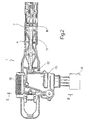
- Figure 1 shows a section of a preferred embodiment of the handle according to the present invention;
- Figure 2 shows an underside view of the Figure 1 handle;
- Figure 3 shows a larger-scale section along line III-III in Figure 2.
-
-
Number 1 in Figure 1 indicates as a whole a handle for activating a lock (not shown) of avehicle door 3. -
Handle 1 comprises a connectingstructure 4 for connection todoor 3; and ahollow control lever 5 hinged to connectingstructure 4 to rotate about an axis, and which, in use, is gripped manually by a user.Handle 1 also comprises a detectingassembly 6 for detecting the intention of the user to open the respective door. More specifically,assembly 6 comprises amagnetic device 7 for detecting the presence of the user's hand close to controllever 5, and for supplying a user-present signal to a known control unit 8 - shown schematically in Figures 1 and 2 - which, on receiving the signal, and after reading, in known manner, an identification code carried by the user, provides for setting the lock (not shown) to a safety-offmode enabling door 3 to be opened. - As shown, particularly in Figure 1, detecting
device 7 comprises a wire aerial 12 having afirst portion 13 extending insidecontrol lever 5, and asecond end portion 14 housed inside aseat 15 onstructure 4 and wound about apin 16 connected integrally tostructure 4 and extending parallel to the rotation axis oflever 5. - As shown in Figure 1 and particularly in Figure 2,
structure 4 is also fitted, preferably by means of one ormore screws 18, with a conductingmember 19 in the form of a strip, conveniently a metal strip, which is connected to aerial 12 by asliding connection 20. More specifically,member 19 has anend portion 21 facingpin 16 and cooperating in sliding manner withend portion 14 of aerial 12 wound aboutpin 16. - As shown in Figure 2, at the opposite end to
portion 21,strip member 19 has anend portion 22 connected in known manner to a known interface circuit (not shown), which is housed inside a cavity, onstructure 4, closed by acover 23, and provides, in use, for receiving a presence signal from aerial 12, and for supplying a corresponding signal to controlunit 8. - As shown in Figure 3,
assembly 6 also comprises a furtherelectromechanical detecting device 24 in parallel withdevice 7, and which provides for detecting rotation ofcontrol lever 5 with respect to connectingstructure 4, and supplying a signal tounit 8. More specifically,electromechanical device 24 comprises apushbutton switch 25 housed inside a sealedchamber 26 formed instructure 4 and having an inlet opening 27 closed by aseal 28.Electromechanical device 24 also comprises amechanical transmission 29 in turn comprising a known activatinglever 30, an intermediate portion of which is hinged tostructure 4 to rotate about anaxis 31 perpendicular topin 16, and anend portion 32 forced by aspring 35 against anappendix 33 integral withlever 5.Portion 32 rests on anend portion 36 of a rocker arm lever 37 for activatingswitch 25. - In the particular example described, rocker arm lever 37 comprises an
intermediate portion 38 hinged tostructure 4 to rotate about anaxis 38a parallel toaxis 31; and, at the opposite end toportion 36, anend portion 39 facingseal 28 to act directly onswitch 25. -
Portion 36 is maintained contactinglever 30 by acompression spring 40 compressed between connectingstructure 4 and a portion of lever 37 extending betweenportions -
Handle 1 according to the present invention operates as follows. - As the user approaches the vehicle, a known aerial (not shown) reads, in known manner, an identification code carried by the user, and supplies
unit 8 with a recognition signal to activate or alertunit 8. At this point, as the user's hand approaches handle 1,magnetic aerial 12 detects the variation in the magnetic field and supplies the interface circuit (not shown) with a signal via slidingconnection 20 andstrip member 19; the interface circuit in turn supplies a signal to controlunit 8, which, in response, releases the various lock safety devices to enable the user to open the doors by turningrespective levers 5. - In the event of a fault on
magnetic device 7,electromechanical device 24 intervenes whencontrol lever 5 is rotated by the user. More specifically, rotation oflever 5 into the open position rotateslever 30 clockwise, in Figure 3, aboutrespective axis 31, so that rocker arm lever 37 rotates anticlockwise, in Figure 3, aboutaxis 38a, andend portion 39 of lever 37 elastically deformsseal 28 to activateswitch 25. Uponswitch 25 being activated, the interface circuit supplies a signal to controlunit 8, which releases the safety devices on the locks. - The advantages of
handle 1 will be clear from the foregoing description. - In particular, by virtue of comprising a
magnetic detecting device 7, i.e. capable of detecting the variation in a magnetic field caused by the presence of the user's hand,assembly 6 as described is obviously not only extremely straightforward to produce, but also provides for a consistently high degree of reliability and efficiency. Furthermore, providing anelectromechanical device 24 in parallel withmagnetic device 7 eliminates any problems caused by possible malfunctioning ofmagnetic device 7. - The efficiency and reliability of
assembly 6 are further enhanced by detectingassembly 6 of thehandle 1 described being fully insulated from external agents and not normally requiring maintenance or inspection. - Clearly, changes may be made to handle 1 as described and illustrated herein without, however, departing from the scope of the present invention as defined in the appended claims. In particular, a magnetic detecting aerial other than the one described by way of example may be provided. Furthermore,
pushbutton switch 25 may be activated by a mechanical transmission other than that described. - Moreover,
switch 25 and respectivemechanical transmission 29 ofhandle 1 described may be dispensed with. - Finally,
switch 25 ofhandle 1 described may also be used to release the lock, in the event the lock is also released electrically like the safety device.
Claims (13)
- A handle (1) for a vehicle door (3), comprising
a connecting structure (4) for connection to a supporting body;
a movable control member (5) hinged to said connecting structure (4) to rotate with respect to said connecting structure (4) about a hinge axis and activated, in use, by the hand of a user;
and detecting means (6) for detecting the presence of said hand proximate said movable control member (5) and for supplying a presence signal to an electronic control unit (8), said detecting means (6) comprisingcharacterized in that said connecting means (20) comprise a sliding connection.magnetic sensing means (12), associated with said connecting structure (4) and at least partly housed in said movable control member (5), to detect the variation in a magnetic field caused by the presence of the hand of the user proximate said movable control member (5),transmitting means (19) for transmitting said presence signal and extending through said connecting structure (4) andconnecting means (20) for connecting said magnetic sensing means (12) to said transmitting means (19), - A handle as claimed in Claim 1, characterized in that said magnetic sensing means comprise a first elongated metal member (12).
- A handle as claimed in Claim 1 or 2, characterized in that said connecting means (20) comprise a supporting member (16) carried by said lever (5); said magnetic sensing means (12) being partly wound about said supporting member (16).
- A handle as claimed in Claim 3, characterized in that said connecting means (20) comprise an intermediate portion of said elongated metal member (12).
- A handle as claimed in Claim 4, characterized in that said transmitting means comprise a second elongated metal member (19) in turn comprising a portion (21) cooperating in sliding manner with the intermediate portion of said first elongated metal member (12).
- A handle as claimed in Claim 5, characterized in that said first elongated metal member (12) is a wire member, and said second elongated metal member (19) is a strip member.
- A handle as claimed in any one of the foregoing Claims, characterized by comprising further detecting means (24) for detecting displacement of the movable control member (5) with respect to the connecting structure (4).
- A handle as claimed in Claim 7, characterized in that said further detecting means (24) are located in parallel with said detecting means (6).
- A handle as claimed in Claim 8, characterized in that said further detecting means (24) comprise switch means (25); and a mechanical transmission (29) interposed between the movable control member (5) and said switch means (25) to activate said switch means (25).
- A handle as claimed in Claim 9, characterized in that said mechanical transmission (29) comprises at least a first rocker arm lever (37).
- A handle as claimed in Claim 10, characterized in that said first rocker arm lever (37) comprises an intermediate portion (38) hinged to said connecting structure (4); an end portion (39) which acts on said switch means (25); and an opposite end portion (36) resting on an activating member (30) associated with said movable control member (5).
- A handle as claimed in Claim 11, characterized in that said mechanical transmission (29) also comprises elastic means (40) interposed between said rocker arm lever (37) and said connecting structure (4) to keep said opposite end portion (36) resting constantly on said activating member (30).
- A handle as claimed in Claim 11 or 12, characterized in that said switch means (25) are housed inside a sealed chamber (26) formed in said connecting structure (4).
Applications Claiming Priority (2)
| Application Number | Priority Date | Filing Date | Title |
|---|---|---|---|
| ITTO980926 | 1998-11-03 | ||
| IT1998TO000926A IT1305155B1 (en) | 1998-11-03 | 1998-11-03 | HANDLE FOR A VEHICLE DOOR. |
Publications (3)
| Publication Number | Publication Date |
|---|---|
| EP0999324A2 EP0999324A2 (en) | 2000-05-10 |
| EP0999324A3 EP0999324A3 (en) | 2000-09-13 |
| EP0999324B1 true EP0999324B1 (en) | 2005-05-04 |
Family
ID=11417154
Family Applications (1)
| Application Number | Title | Priority Date | Filing Date |
|---|---|---|---|
| EP99121668A Expired - Lifetime EP0999324B1 (en) | 1998-11-03 | 1999-11-02 | Vehicle door handle |
Country Status (4)
| Country | Link |
|---|---|
| US (1) | US6588813B1 (en) |
| EP (1) | EP0999324B1 (en) |
| DE (1) | DE69925089T2 (en) |
| IT (1) | IT1305155B1 (en) |
Families Citing this family (36)
| Publication number | Priority date | Publication date | Assignee | Title |
|---|---|---|---|---|
| FR2810958B1 (en) * | 2000-06-29 | 2002-09-06 | Valeo Securite Habitacle | LOCK CONTROL ASSEMBLY FOR A MOTOR VEHICLE OPENING AND OPENING PROVIDED WITH SUCH AN ASSEMBLY |
| DE10107121A1 (en) * | 2001-02-14 | 2002-08-29 | Valeo Sicherheitssysteme Gmbh | Vehicle door for a convertible |
| JP3614789B2 (en) * | 2001-03-28 | 2005-01-26 | 株式会社ホンダロック | Vehicle out-handle device |
| FR2826998B1 (en) * | 2001-07-05 | 2004-01-30 | Philippe Louvel | DOOR HANDLE EQUIPPED WITH AUTOMATIC RETRACTABLE PORTILLON |
| DE10139886B4 (en) | 2001-08-20 | 2020-07-23 | Huf Hülsbeck & Fürst Gmbh & Co. Kg | Door handle arrangement for a motor vehicle door |
| FR2833292B1 (en) * | 2001-12-12 | 2004-06-18 | Valeo Electronique | SYSTEM FOR DETECTING THE PRESENCE OF A USER, PARTICULARLY FOR A MOTOR VEHICLE |
| EP1347132B1 (en) * | 2002-03-19 | 2007-01-03 | Ford Global Technologies, LLC | Vehicle door system comprising lock indicator |
| US20030216817A1 (en) * | 2002-05-16 | 2003-11-20 | Richard Pudney | Vehicle access system with sensor |
| DE50300798D1 (en) * | 2002-09-20 | 2005-08-25 | Porsche Ag | Locking device for a vehicle door |
| JP4161664B2 (en) * | 2002-09-27 | 2008-10-08 | アイシン精機株式会社 | Vehicle door handle device |
| ITMI20022250A1 (en) * | 2002-10-23 | 2004-04-24 | Valeo Sicurezza Abitacolo Spa | DOOR HANDLE, DOORS OR SIMILAR, IN PARTICULAR |
| JP4015568B2 (en) * | 2003-01-29 | 2007-11-28 | アイシン精機株式会社 | Outside handle device and connector structure thereof |
| DE10348719A1 (en) * | 2003-10-16 | 2005-05-12 | Huf Huelsbeck & Fuerst Gmbh | Outside door handle, especially for vehicles, contains transmission and excitation electrodes associated with capacitive locking and unlocking sensors |
| DE102004009366A1 (en) * | 2004-02-26 | 2005-09-15 | D. la Porte Söhne GmbH | Actuator for a lock |
| JP4443307B2 (en) * | 2004-05-31 | 2010-03-31 | 株式会社アルファ | Door handle device |
| EP1797960B1 (en) * | 2004-07-23 | 2014-10-15 | Aisin Seiki Kabushiki Kaisha | Door handle device for vehicle |
| US7568744B2 (en) * | 2005-09-22 | 2009-08-04 | Nissan Technical Center North America, Inc. | Vehicle door handle assembly |
| US7501595B2 (en) * | 2005-10-06 | 2009-03-10 | Strattec Security Corporation | Self-compensating motion detector |
| JP2007138565A (en) * | 2005-11-18 | 2007-06-07 | Aisin Seiki Co Ltd | Vehicle door opening and closing device |
| US7469503B2 (en) * | 2006-02-02 | 2008-12-30 | Toyota Motor Engineering & Manufacturing North America, Inc. | Outside gasket for a vehicle handle exhibiting wind redirection characteristics |
| USD564855S1 (en) * | 2007-02-21 | 2008-03-25 | Trimark Corporation | Remote pull handle |
| FR2915796B1 (en) * | 2007-05-03 | 2009-06-12 | Siemens Vdo Automotive Sas | DEVICE FOR REMOVING THE INTERFERENCE PHENOMENON BETWEEN CAPACITIVE DETECTION AREAS OF A SENSOR |
| USD619871S1 (en) * | 2008-10-28 | 2010-07-20 | D. la Porte Söhne GmbH | Vehicle door handle |
| IT1395117B1 (en) * | 2009-07-29 | 2012-09-05 | Valeo Spa | PROCEDURE FOR ASSEMBLING A HANDLE IN A DOOR OF A MOTOR VEHICLE AND ITS DOOR HANDLE |
| US9062478B2 (en) * | 2010-08-13 | 2015-06-23 | Adac Plastics, Inc. | Door handle assembly |
| USD688112S1 (en) * | 2012-03-29 | 2013-08-20 | Ford Motor Company | Vehicle rear door handle |
| US9957737B2 (en) | 2012-06-29 | 2018-05-01 | Ford Global Technologies, Llc | Flush-mounted door handle for vehicles |
| US8701353B2 (en) | 2012-06-29 | 2014-04-22 | Ford Global Technologies, Llc | Deployable door handle for vehicles |
| JP5932609B2 (en) * | 2012-11-08 | 2016-06-08 | 株式会社ホンダロック | Outdoor handle device for vehicle door |
| USD712232S1 (en) * | 2013-03-07 | 2014-09-02 | Paccar Inc | Door release |
| KR101481352B1 (en) * | 2013-12-19 | 2015-01-12 | 현대자동차주식회사 | Door ourside handle |
| JP5972919B2 (en) * | 2014-02-04 | 2016-08-17 | 本田技研工業株式会社 | Vehicle door device |
| US9145712B1 (en) * | 2014-12-17 | 2015-09-29 | I-Tek Metal Mfg. Co., Ltd. | Lock cylinder for a door lock |
| CN107849866B (en) * | 2015-07-13 | 2020-09-25 | 胡夫·许尔斯贝克和福斯特有限及两合公司 | Outside door handles for vehicles |
| US12546150B2 (en) * | 2021-01-07 | 2026-02-10 | Ford Global Technologies, Llc | Door assembly for motor vehicle |
| DE102024201579A1 (en) * | 2023-02-21 | 2024-08-22 | Witte Automotive Gmbh | Handle module, especially external handle module |
Family Cites Families (20)
| Publication number | Priority date | Publication date | Assignee | Title |
|---|---|---|---|---|
| US6397136B1 (en) * | 1997-02-06 | 2002-05-28 | Automotive Technologies International Inc. | System for determining the occupancy state of a seat in a vehicle |
| DE19516316C2 (en) * | 1995-05-04 | 1998-11-26 | Kiekert Ag | Safety device on a motor vehicle, which only allows a person authorized to open the motor vehicle to open the motor vehicle |
| DE19617038C2 (en) * | 1996-04-27 | 2000-11-30 | Huf Huelsbeck & Fuerst Gmbh | Locking system, in particular for motor vehicles |
| FR2750155B1 (en) * | 1996-06-25 | 1998-09-04 | Valeo Securite Habitacle | DEVICE FOR CONTROLLING THE OPENING OF A LOCK OF A MOTOR VEHICLE OPENING ELEMENT |
| DE19633894C2 (en) | 1996-08-22 | 1999-12-23 | Huf Huelsbeck & Fuerst Gmbh | Device for actuating a lock installed in a door, a flap or the like, in particular in a vehicle |
| JPH10159419A (en) * | 1996-11-29 | 1998-06-16 | Aisin Seiki Co Ltd | Automatic door lock control device |
| US6042159A (en) * | 1997-08-01 | 2000-03-28 | Adac Plastics, Inc. | Door handle assembly |
| US6163971A (en) * | 1997-09-10 | 2000-12-26 | Accura Design, Inc. | Automatic foot sizing apparatus |
| BE1011501A7 (en) * | 1997-10-17 | 1999-10-05 | Staar Marcel | Identification system articles for equipment sale hotel rooms. |
| DE19748327A1 (en) * | 1997-10-31 | 1999-05-20 | Siemens Ag | Antenna device, in particular for an anti-theft system of a motor vehicle |
| JP3380729B2 (en) * | 1997-12-04 | 2003-02-24 | 三井金属鉱業株式会社 | Vehicle sliding door opening and closing control device |
| FR2778427B1 (en) * | 1998-05-05 | 2000-06-23 | Valeo Securite Habitacle | SECURITY SYSTEM FOR A MOTOR VEHICLE OPENING ELEMENT |
| US6236333B1 (en) * | 1998-06-17 | 2001-05-22 | Lear Automotive Dearborn, Inc. | Passive remote keyless entry system |
| FR2781246B1 (en) * | 1998-07-17 | 2000-08-18 | Valeo Securite Habitacle | SECURITY SYSTEM FOR A MOTOR VEHICLE OPENING ELEMENT WITH IMPROVED CONNECTION MEANS |
| FR2781247B1 (en) * | 1998-07-17 | 2000-08-18 | Valeo Securite Habitacle | SECURITY SYSTEM FOR A MOTOR VEHICLE OPENING ELEMENT HAVING A PROTECTIVE COVER |
| US6343140B1 (en) * | 1998-09-11 | 2002-01-29 | Quid Technologies Llc | Method and apparatus for shooting using biometric recognition |
| IT1305154B1 (en) * | 1998-11-03 | 2001-04-10 | Valeo Sicurezza Abitacolo Spa | HANDLE FOR A VEHICLE DOOR. |
| US6034617A (en) * | 1998-12-04 | 2000-03-07 | Eaton Corporation | Operator intent based passive keyless vehicle control system |
| FR2789433B1 (en) * | 1999-02-05 | 2001-04-13 | Valeo Securite Habitacle | SECURITY SYSTEM FOR A MOTOR VEHICLE OPENING ELEMENT |
| US6234041B1 (en) * | 1999-08-23 | 2001-05-22 | Adac Plastics, Inc. | Combined cushion and seal for vehicular door handle assembly |
-
1998
- 1998-11-03 IT IT1998TO000926A patent/IT1305155B1/en active
-
1999
- 1999-11-02 US US09/432,394 patent/US6588813B1/en not_active Expired - Lifetime
- 1999-11-02 DE DE69925089T patent/DE69925089T2/en not_active Expired - Lifetime
- 1999-11-02 EP EP99121668A patent/EP0999324B1/en not_active Expired - Lifetime
Also Published As
| Publication number | Publication date |
|---|---|
| EP0999324A2 (en) | 2000-05-10 |
| US6588813B1 (en) | 2003-07-08 |
| DE69925089D1 (en) | 2005-06-09 |
| IT1305155B1 (en) | 2001-04-10 |
| DE69925089T2 (en) | 2006-01-19 |
| EP0999324A3 (en) | 2000-09-13 |
| ITTO980926A1 (en) | 2000-05-03 |
Similar Documents
| Publication | Publication Date | Title |
|---|---|---|
| US6588813B1 (en) | Vehicle door handle | |
| US12098578B2 (en) | Door leaf handle device, in particular for vehicle | |
| EP0999325B2 (en) | Vehicle door handle | |
| US6648493B2 (en) | External actuating mechanism for vehicle locks | |
| EP1111171B2 (en) | Security system for an opening of an automobile equipped with switches without mechanical action | |
| US6002341A (en) | Door lock control apparatus for a vehicle | |
| EP1659543B1 (en) | Security system and portable device usable therein | |
| CN102597392B (en) | Handle device having a mechanical return mechanism | |
| US7504601B2 (en) | Sensor module for releasing vehicle windows and the like | |
| US20080258911A1 (en) | Exit alarm escutcheon | |
| US20020046440A1 (en) | Vehicle door handle | |
| EP1128002A2 (en) | Vehicle door handle | |
| FR2847930A1 (en) | System to operate doors of a motor vehicle, uses extra sensor and actuator so passenger door is automatically unlocked as person approaches once driver has been identified as present | |
| US20050151635A1 (en) | External opening control for doors and the like | |
| GB2146063A (en) | Improvements in or relating to door or window fasteners | |
| US5777395A (en) | Safety actuation of vehicle door-handle operated door locks using series connected switches and electric actuator | |
| EP1041226A1 (en) | Device for securing a motor vehicle access system equipped with identification means and an identifier | |
| WO2011073271A9 (en) | Device for activating a hands-free system | |
| US20210010303A1 (en) | Door leaf handle for a motor vehicle | |
| WO1999031339A8 (en) | Actuating device for an electric lock of a motor vehicle door | |
| US4935587A (en) | Device for actuating a warning device in combination with a lock for a door, window or the like | |
| EP0829602B1 (en) | Vehicle door lock assembly | |
| EP1362154A1 (en) | Device for actuating a lock | |
| FR2801714A1 (en) | Anti-theft system for electronic device with slot such as notebook computer triggers alarm in receiver if code signal is no longer received from transmitter inserted in slot | |
| KR100941103B1 (en) | Hood switch for a car |
Legal Events
| Date | Code | Title | Description |
|---|---|---|---|
| PUAI | Public reference made under article 153(3) epc to a published international application that has entered the european phase |
Free format text: ORIGINAL CODE: 0009012 |
|
| AK | Designated contracting states |
Kind code of ref document: A2 Designated state(s): DE FR GB |
|
| AX | Request for extension of the european patent |
Free format text: AL;LT;LV;MK;RO;SI |
|
| PUAL | Search report despatched |
Free format text: ORIGINAL CODE: 0009013 |
|
| AK | Designated contracting states |
Kind code of ref document: A3 Designated state(s): AT BE CH CY DE DK ES FI FR GB GR IE IT LI LU MC NL PT SE |
|
| AX | Request for extension of the european patent |
Free format text: AL;LT;LV;MK;RO;SI |
|
| RIC1 | Information provided on ipc code assigned before grant |
Free format text: 7E 05B 7/00 A, 7E 05B 17/22 B, 7E 05B 47/00 B, 7E 05B 65/20 B |
|
| 17P | Request for examination filed |
Effective date: 20010307 |
|
| AKX | Designation fees paid |
Free format text: DE FR GB |
|
| 17Q | First examination report despatched |
Effective date: 20030919 |
|
| GRAP | Despatch of communication of intention to grant a patent |
Free format text: ORIGINAL CODE: EPIDOSNIGR1 |
|
| GRAS | Grant fee paid |
Free format text: ORIGINAL CODE: EPIDOSNIGR3 |
|
| GRAA | (expected) grant |
Free format text: ORIGINAL CODE: 0009210 |
|
| AK | Designated contracting states |
Kind code of ref document: B1 Designated state(s): DE FR GB |
|
| REG | Reference to a national code |
Ref country code: GB Ref legal event code: FG4D |
|
| REF | Corresponds to: |
Ref document number: 69925089 Country of ref document: DE Date of ref document: 20050609 Kind code of ref document: P |
|
| PG25 | Lapsed in a contracting state [announced via postgrant information from national office to epo] |
Ref country code: GB Free format text: LAPSE BECAUSE OF NON-PAYMENT OF DUE FEES Effective date: 20051102 |
|
| ET | Fr: translation filed | ||
| PLBE | No opposition filed within time limit |
Free format text: ORIGINAL CODE: 0009261 |
|
| STAA | Information on the status of an ep patent application or granted ep patent |
Free format text: STATUS: NO OPPOSITION FILED WITHIN TIME LIMIT |
|
| 26N | No opposition filed |
Effective date: 20060207 |
|
| GBPC | Gb: european patent ceased through non-payment of renewal fee |
Effective date: 20051102 |
|
| PGFP | Annual fee paid to national office [announced via postgrant information from national office to epo] |
Ref country code: DE Payment date: 20141113 Year of fee payment: 16 |
|
| PGFP | Annual fee paid to national office [announced via postgrant information from national office to epo] |
Ref country code: FR Payment date: 20141201 Year of fee payment: 16 |
|
| REG | Reference to a national code |
Ref country code: DE Ref legal event code: R119 Ref document number: 69925089 Country of ref document: DE |
|
| REG | Reference to a national code |
Ref country code: FR Ref legal event code: ST Effective date: 20160729 |
|
| PG25 | Lapsed in a contracting state [announced via postgrant information from national office to epo] |
Ref country code: DE Free format text: LAPSE BECAUSE OF NON-PAYMENT OF DUE FEES Effective date: 20160601 |
|
| PG25 | Lapsed in a contracting state [announced via postgrant information from national office to epo] |
Ref country code: FR Free format text: LAPSE BECAUSE OF NON-PAYMENT OF DUE FEES Effective date: 20151130 |