EP0999005B1 - Spannfutter für eine Werkzeugmaschine - Google Patents
Spannfutter für eine Werkzeugmaschine Download PDFInfo
- Publication number
- EP0999005B1 EP0999005B1 EP99110962A EP99110962A EP0999005B1 EP 0999005 B1 EP0999005 B1 EP 0999005B1 EP 99110962 A EP99110962 A EP 99110962A EP 99110962 A EP99110962 A EP 99110962A EP 0999005 B1 EP0999005 B1 EP 0999005B1
- Authority
- EP
- European Patent Office
- Prior art keywords
- clamping
- chuck
- adjusting
- accordance
- tilting
- Prior art date
- Legal status (The legal status is an assumption and is not a legal conclusion. Google has not performed a legal analysis and makes no representation as to the accuracy of the status listed.)
- Expired - Lifetime
Links
Images




Classifications
-
- B—PERFORMING OPERATIONS; TRANSPORTING
- B23—MACHINE TOOLS; METAL-WORKING NOT OTHERWISE PROVIDED FOR
- B23B—TURNING; BORING
- B23B31/00—Chucks; Expansion mandrels; Adaptations thereof for remote control
- B23B31/02—Chucks
- B23B31/10—Chucks characterised by the retaining or gripping devices or their immediate operating means
- B23B31/12—Chucks with simultaneously-acting jaws, whether or not also individually adjustable
- B23B31/1261—Chucks with simultaneously-acting jaws, whether or not also individually adjustable pivotally movable in a radial plane
-
- B—PERFORMING OPERATIONS; TRANSPORTING
- B23—MACHINE TOOLS; METAL-WORKING NOT OTHERWISE PROVIDED FOR
- B23B—TURNING; BORING
- B23B31/00—Chucks; Expansion mandrels; Adaptations thereof for remote control
- B23B31/02—Chucks
- B23B31/10—Chucks characterised by the retaining or gripping devices or their immediate operating means
- B23B31/12—Chucks with simultaneously-acting jaws, whether or not also individually adjustable
- B23B31/18—Chucks with simultaneously-acting jaws, whether or not also individually adjustable pivotally movable in planes containing the axis of the chuck
-
- B—PERFORMING OPERATIONS; TRANSPORTING
- B23—MACHINE TOOLS; METAL-WORKING NOT OTHERWISE PROVIDED FOR
- B23B—TURNING; BORING
- B23B31/00—Chucks; Expansion mandrels; Adaptations thereof for remote control
- B23B31/02—Chucks
- B23B31/24—Chucks characterised by features relating primarily to remote control of the gripping means
- B23B31/28—Chucks characterised by features relating primarily to remote control of the gripping means using electric or magnetic means in the chuck
-
- B—PERFORMING OPERATIONS; TRANSPORTING
- B23—MACHINE TOOLS; METAL-WORKING NOT OTHERWISE PROVIDED FOR
- B23B—TURNING; BORING
- B23B2260/00—Details of constructional elements
- B23B2260/108—Piezoelectric elements
Definitions
- the present invention relates to a chuck for a machine tool according to the Preamble of claim 1.
- Such a chuck is known in the art e.g. known as a membrane chuck or from FR 1 163 300 A.
- the object of the invention is to provide a chuck that can be easily adjusted Clamping forces on different workpieces and different processing allowed, and to specify a tax procedure to do so.
- a chuck 1 with a A plurality of clamping jaws 2 are provided.
- the jaws 2 are with a chuck base 4 connected via a control module 3.
- the chuck base 4 is with the Workpiece spindle 5 of the machine tool connected such that the movements of the Tool spindle such as rotary movements, feed movements etc. to the chuck 1 be transmitted.
- the workpiece spindle 5 is via bearing 7 with the workpiece spindle structure 8 of the machine bed 9 of the machine tool connected.
- the control modules 3 each consist of a piezo rotary control element 3.
- a piezo rotary control element 3 has a base plate X1, which is connected to the chuck base 4 is a tilting plate X2, which is connected to the corresponding clamping jaw 2, Piezo actuator elements X3, the dimension of which in a longitudinal direction in a known manner is controllably changeable by applying electrical voltage, and a tensioning element X4 on, wherein the actuating elements X3 are arranged such that their longitudinal directions are parallel to each other and the base plate X1 and the tilt plate X2 in the longitudinal direction are arranged above and below the control elements, and the clamping element X4 in the middle is arranged between the two actuating elements X3 and the base plate X1 and Tilting plate X2 with the adjusting elements arranged between them with a predetermined one Tension.
- the control elements come with opposing voltage changes controlled, i.e. when a voltage change to the one piezo actuator in one direction (positive or negative), then the other Piezo actuator an opposite (negative or positive) voltage change created. This results in an opposite (antisymmetric) change in length of the two piezo actuators. Since the length of the control module 3 by the bias with the clamping element X4 is determined by the opposite change in length the piezo actuating elements X3 a rotary movement of the tilting plate X1 by a (virtual) Pivot point X5 caused.
- the control modules are also temperature-compensated in this way, i.e. a change in temperature does not lead to movements.
- An example of control modules the type described is disclosed in DE 196 46 511 C1. The technical data of a commercially available control module of this type are shown in the table in FIG. 4.
- Each clamping jaw 2 is by one by means of the corresponding adjusting module 3 (Virtual) fulcrum, namely the fulcrum X5 of the corresponding control module movable.
- a workpiece 6 can thus be controlled by moving the clamping jaws 2, as will be described later.
- the control structure for the chuck is shown schematically in FIG. 5.
- the control modules 3 each have control electronics 10 which are connected via a contactless Energy and data transmission device 11 with voltage and with control data is supplied.
- the control data are provided by a controller 12 for each of the control modules 3 generated.
- the control modules 3 can be individually controlled in such a way that the individual clamping jaws 2 controlled independently of the other jaws 2 in a simple manner can be moved.
- the control electronics 10 is not shown in Fig. 1, but it is preferred arranged between and / or behind the jaws, so that the space required for rotating control electronics, which is already small, the size of the chuck not increased, especially not in the radial direction.
- the controller 12 communicates with the higher-level control 15 of the machine tool.
- the non-contact energy and data transmission device 11 is by coils in the mutually facing sides of the workpiece spindle assembly (workpiece spindle head) 8 and the chuck base 4, so that the space required for it is very low is.
- the energy and data transmission device could contact e.g. be designed as sliding contacts.
- the direct connection of the clamping jaws is eliminated 2 with the control modules 3 and the direct control via these all interposed mechanical elements. This significantly reduces the number of parts and the Size is greatly reduced.
- Sensors are preferably arranged in the chuck, which sensors Measure the clamping force of each jaw. The information obtained in this way is sent to the Control electronics 10 and / or the controller 12 supplied.
- the individual jaws 2 can thus be fed back via the sensors in every stage of processing to exert a precisely specified clamping force can be controlled, regardless of the actual form of origin of each Workpiece can also be adhered to exactly.
- a suitable sensor e.g. B. by detecting the motor current of one Grinding wheel driving motor.
- With a fixed tool like one Turning steel is e.g. the motor current of the workpiece drive or the infeed value used by the NC control to calculate the machining force.
- the principle is to maintain
- sensors can be arranged that the of each jaw Record the travel distance.
- the information obtained in this way is sent to the Control electronics 10 and / or the controller 12 supplied.
- a conversion rule from the control electronics 10 and / or the controller 12 exerted clamping force can be calculated. This solution may be due to the cost of the Sensors be cheaper than the direct detection of the clamping force.
- information about the actual one can also be obtained via the travel path Gain deformation of the workpiece currently held. This deformation information is then used to calculate the permissible clamping forces (in the predetermined Rule for determining the clamping forces)
- the predetermined rule may e.g. B. by a calculation rule in the software of the Control program is realized, or through a table of values in the controller is stored and e.g. an assignment of machining force, speed of the workpiece spindle and contains clamping force per clamping jaw, can be realized.
- the measurement of the movement carried out for each clamping jaw enables another Control option, namely the corresponding workpiece positioning relative to Tool to move (e.g. the center of an axis hole) to certain Execute machining (e.g. compensate for non-circular contours).
- a sensor 14 for detecting the Provided against the workpiece which is connected to the controller 12.
- centrifugal forces caused by the rotation of the chuck can of course in a conventional manner by means of appropriately arranged counterweights on the jaws, which are not shown in Fig. 1. It is with the first one Embodiment but possible, these centrifugal forces individually for each jaw 2 to compensate by means of the control modules 3.
- the main part of the centrifugal forces is counterweights compensated so that the center of gravity of the jaw approximately at the pivot point X5 of the Control module 3 is.
- the variation in centrifugal forces, e.g. through the wear of the Clamping jaws and the resulting regrinding of the clamping jaws occurs, is compensated by the control modules 3. This compensation takes place in the described feedback way. Therefore, even deformations of the workpiece geometry, that could arise from such centrifugal variations.
- The is at the now occurring speeds of the workpiece spindles of up to 10,000 rpm is a not insignificant advantage.
- the individually regulated setting of the clamping forces could in principle also be done by means of hydraulic or pneumatic solutions. Owing to so-called stick-slip effects, i.e. due to the comparatively high internal friction such systems in mechanical bearings and actuators effects that Changes in the forces exerted only in relatively large change steps high-precision settings are only possible with great effort. at In the first embodiment, however, control modules are used which are relatively small have internal friction and therefore with comparatively little effort allow high-precision control.
- the jaws are in the conventional manner to a predetermined position of the clamping jaws 2 in contact with the workpiece 6 or placed near the workpiece 6. This is done e.g. in that the part of the Chuck base 4, on which the control modules 3 are attached, as a membrane chuck or wedge hook chuck or similar (not shown) is formed. This conventional one The chuck is then relative to the predetermined position in a known manner operated the workpiece 6 and then locked in this position. The further travel path the individual jaws 2 is then set in the manner described above. As a result, the control modules 3 and the transmission path of their control movement can be so be trained that only a very small part of the necessary total travel of this is delivered.
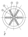
- FIGS. 2 and 3 a second embodiment of the Chuck described. Except for the differences described below the structure and control of the second embodiment of the first embodiment. Sections and parts that have the same or comparable functions are included the same reference numerals as in the first embodiment.
- the second Embodiment of the invention is shown in Fig. 2 schematically in a cross section along the Axis of rotation A of a spindle is shown so that only that above the axis of rotation Section of the chuck 1 is shown.
- the chuck 1 is provided with a plurality of jaws 2 (e.g. 6 jaws, such as It is shown in Fig. 3), each having a movement section 2a interchangeable jaw end piece 2b, a counterweight section 2c Bend joint 2d, an actuator connection section 2e and an L-shaped base connection section 2f have.
- the moving section 2a, the counterweight section 2c, the flexible joint 2d, the actuator connection section 2e and the Base connection section 2f are formed in one piece, wherein the flexible joint 2d Moving section 2a and the base connecting section 2f hingedly connected.
- One control module 3 each is in a clamping jaw 2 between the control module connection section 2e and the base connection section 2f.
- the actuator connection section 2e has one that faces the tilting plate X2 and is connected to it Plate section on.
- the L-shaped base connecting portion 2f has the shape of a lying L, the lower part of the L having a recess into which the Base plate X1 of the control module 3 is inserted.
- the chuck has a chuck base 4 which has a chuck base base portion 4a, a chuck base end portion 4c and a chuck base connecting portion 4b that connects them.
- the L-shaped base connection section 2f is firmly connected to the chuck base 4, e.g. by projections that in Recesses of the chuck base are inserted, and by bolts etc.
- the base plates X1 of the adjusting modules 3 of the individual clamping jaws 2 are also (via the interposed base connection portion 2f) firmly with the chuck base 4 connected.
- the freedom of movement around the individual jaws is in the chuck by a seal 15 against the ingress of dirt and Machining residues such as chips and lubricant and coolant residues are protected.
- the chuck base base section 4a is a cavity 16 for receiving the control electronics (see 10 in Fig. 5) of the control module 3 is provided.
- the one for the chuck part of the contactless energy and data transmission device 11 is included connected to the cavity 16.
- the clamping jaws 2 with the adjusting modules 3 also directly connected.
- the jaws are deflected directly under Deflection by the 2d flexible joint.
- the internal friction of such flexible joints is however comparatively small, so that even with the second embodiment a very accurate Control of the individual jaws is guaranteed.
- the number of parts drops also clear and the size is also greatly reduced.
- the flexible joint is not like that in FIG. 2 Embodiment shown on the side of the clamping jaw facing the axis of rotation A. but formed on the side facing away from the axis of rotation. This becomes the main burden of the bending joint instead of a tensile load.
- the second embodiment can be the developments of the first embodiment exhibit.
- the chuck according to the embodiments of the invention enables the to regulate the tension applied in very fine increments.
- the compact design of the clamping jaws and the actuators enables a large one Number of jaws in the chuck without greatly increasing the size increase.
- the greater the number of clamping jaws the finer the exercise can be Clamping force can be distributed to the workpiece and to a specific section clamping force exerted on the workpiece can be regulated.
Landscapes
- Engineering & Computer Science (AREA)
- Mechanical Engineering (AREA)
- Gripping On Spindles (AREA)
Description
- Fig. 1
- eine Querschnittsdarstellung einer ersten Ausführungsform;
- Fig. 2
- eine Querschnittsdarstellung einer zweiten Ausführungsform;
- Fig. 3
- eine Vorderansicht der zweiten Ausführungsform;
- Fig. 4
- eine Querschnittsdarstellung eines Stellmoduls; und
- Fig. 5
- eine Blockdarstellung einer Steuerung.
Claims (10)
- Spannfutter für eine Werkzeugmaschine zum Einspannen eines Werkstücks, mit einer Spanneinrichtung mit einer Mehrzahl von Spanniucken (2), die jeweils zum Einspannen und Halten eines Werkstücks aus einer Öfimingsstellung in eine Haltestellung bewegbar sind, und
einer Stelleinrichtung zum Bewegen der Spannbacken (2) in die Öffnungsstellung und die Haltestellung,
dadurch gekennzeichnet, daß die Stelleinrichtung eine Mehrzahl von Stellgliedern (3) aufweist von denen jedes so ausgebildet ist, daß es zur Kippbewegung um einen Drehpunkt (X5) steuerbar ist, und jeweils mit einer entsprechenden Spannbacke (2) zum bewegen der Spannbacke in die Haltestellung verbunden ist. - Spannfutter nach Anspruch 1, dadurch gekennzeichnet, daß jedes der Stellglieder ein Medium aufweist, das eine elektrisch und/oder magnetisch steuerbar veränderliche Abmessung aufweist.
- Spannfutter nach Anspruch 1 oder 2, dadurch gekennzeichnet, daß jedes der Stellglieder ein Kippmodul (3) ist, das
eine Grundplatte (X1),
eine Kippplatte (X2),
mindestens zwei Stellelemente (X3), deren Abmessung in einer Längsrichtung elektrisch und/oder magnetisch steuerbar veränderlich ist, und
ein Spannelement (X4)
aufweist, wobei
die Stellelemente derart angeordnet sind, daß ihre Längsrichtungen parallel zueinander sind und die Grundplatte (X1) und die Kippplatte (X2) in Längsrichtung ober- und unterhalb der Stellelemente angeordnet sind, und
das Spannelement (X4) mittig zwischen den mindestens zwei Stellelementen (X3) angeordnet ist und die Grundplatte (X1) und die Kippplatte (X2) mit dazwischen angeordneten Stellelementen mit einer vorbestimmten Spannung vorspannt - Spannfutter nach einem der Ansprüche 1 bis 3, dadurch gekennzeichnet, daß jedes der Stellglieder ein Kippmodul (3) umfasst, das in einer Längsrichtung eine Vorderseite mit einer Kippplatte (X2) und eine Hinterseite mit einer Grundplatte (X1) und dazwischen den Drehpunkt aufweist, zur Ausführung einer gesteuerten Kippbewegung der Kippplatte (X2) relativ zu der Grundplatte (X1),
daß das Spannfutter ein mit einer Spindel (5) der Werkzeugmaschine verbundenes Basisteil (4) aufweist, mit dem die Grundplatten jedes Kippmoduls (3) verbunden sind, und daß die Spannbacken (2) jeweils mit der Kippplatte (X2) des zugehörigen Kippmoduls (3) verbunden sind. - Spannfutter nach Anspruch 4, dadurch gekennzeichnet, daß jede der Spannbacken (2) zusätzlich über ein Biegegelenk (2d) mit dem Basisteil (4) des Spannfutters verbunden ist.
- Spannfutter nach einem der Ansprüche 1 bis 5, dadurch gekennzeichnet, daß für jede Spannbacke ein Sensor zur Erfassung der Spannkraft der von der Spannbacke ausgeübten Spannkraft und/oder des von der Spannbacke gegenüber einer Grundstellung zurückgelegten Stellwegs vorgesehen ist.
- Spannfutter nach einem der Ansprüche 1 bis 6, dadurch gekennzeichnet, daß die Stelleinrichtung ein erstes Stellmittel mit der Mehrzahl von Stellgliedern (3) und ein zweites Stellmittel zum Bewegen der Spannbacken (2) aufweist,
daß das zweite Stellmittel die Spannbacken (2) über einen ersten Teil des Weges zwischen der Öffnungsstellung und der Haltestellung bewegt und das erste Stellmittel über den anderen Teil, und
daß das zweite Stellmittel verriegelbar ist. - Verfahren zur Steuerung eines Spannfutters nach einem der Ansprüche 1 bis 7 beim Einspannen eines Werkstücks bei einer Bearbeitung,
mit den Schritten
Erfassen der von der Werkzeugmaschine auf das eingespannte Werkstück (6) ausgeübten Bearbeitungskraft,
Bestimmen der aufgrund der erfassten Bearbeitungskraft zur Einspannnung des Werkstücks (6) notwendigen Einspannkraft, und
individuelles Ansteuern der Stellglieder (3) derart, daß die Spannbacken (2) die notwendige Spannkraft ausüben. - Verfahren nach Anspruch 8, dadurch gekennzeichnet, daß die von den einzelnen Stellgliedern (3) ausgeübte Spannkraft bestimmt wird und die individuelle Ansteuerung mittels Rückkoppelung der bestimmten Spannkraft aktualisiert wird.
- Verfahren nach Anspruch 9, dadurch gekennzeichnet, daß die Bestimmung der von den einzelnen Stellgliedern (3) ausgeübte Spannkraft derart erfolgt, daß sie mittels eines Sensors gemessen oder aus dem von der Spannbacke zurückgelegten Stellweg berechnet wird.
Priority Applications (3)
| Application Number | Priority Date | Filing Date | Title |
|---|---|---|---|
| EP03012474A EP1344594A1 (de) | 1998-11-02 | 1999-06-08 | Spannfutter |
| DE59913659T DE59913659D1 (de) | 1998-11-02 | 1999-11-02 | Spannfutter für eine Werkzeugmaschine |
| EP19990121698 EP0999004B1 (de) | 1998-11-02 | 1999-11-02 | Spannfutter für eine Werkzeugmaschine |
Applications Claiming Priority (2)
| Application Number | Priority Date | Filing Date | Title |
|---|---|---|---|
| DE19850334 | 1998-11-02 | ||
| DE19850334 | 1998-11-02 |
Related Child Applications (1)
| Application Number | Title | Priority Date | Filing Date |
|---|---|---|---|
| EP03012474A Division EP1344594A1 (de) | 1998-11-02 | 1999-06-08 | Spannfutter |
Publications (2)
| Publication Number | Publication Date |
|---|---|
| EP0999005A1 EP0999005A1 (de) | 2000-05-10 |
| EP0999005B1 true EP0999005B1 (de) | 2003-09-03 |
Family
ID=7886334
Family Applications (2)
| Application Number | Title | Priority Date | Filing Date |
|---|---|---|---|
| EP03012474A Withdrawn EP1344594A1 (de) | 1998-11-02 | 1999-06-08 | Spannfutter |
| EP99110962A Expired - Lifetime EP0999005B1 (de) | 1998-11-02 | 1999-06-08 | Spannfutter für eine Werkzeugmaschine |
Family Applications Before (1)
| Application Number | Title | Priority Date | Filing Date |
|---|---|---|---|
| EP03012474A Withdrawn EP1344594A1 (de) | 1998-11-02 | 1999-06-08 | Spannfutter |
Country Status (4)
| Country | Link |
|---|---|
| EP (2) | EP1344594A1 (de) |
| AT (1) | ATE248679T1 (de) |
| DE (1) | DE59906843D1 (de) |
| ES (1) | ES2207069T3 (de) |
Cited By (1)
| Publication number | Priority date | Publication date | Assignee | Title |
|---|---|---|---|---|
| DE102019110912B3 (de) * | 2019-04-26 | 2020-07-30 | J. Schmalz Gmbh | Verfahren zum Betreiben einer Handhabungsanlage und Blocksauger für eine solche Handhabungsanlage |
Families Citing this family (1)
| Publication number | Priority date | Publication date | Assignee | Title |
|---|---|---|---|---|
| DE102010019677A1 (de) * | 2009-09-24 | 2011-09-29 | Jens Mehnert | Verfahren und Vorrichtung zur Konditionierung von Lagersystemen für Wellen |
Family Cites Families (3)
| Publication number | Priority date | Publication date | Assignee | Title |
|---|---|---|---|---|
| FR1163300A (fr) * | 1956-12-14 | 1958-09-24 | Realisation D App Medicaux Et | Dispositif de serrage, notamment pour mandrins de tour |
| DE3402988A1 (de) * | 1984-01-28 | 1985-08-08 | SMW Schneider & Weißhaupt GmbH, 7996 Meckenbeuren | Einrichtung zur ueberwachung des betriebszustandes eines kraftspannfutters |
| DE4312937A1 (de) * | 1993-04-21 | 1994-10-27 | Mahle Gmbh | Auslenkbare Lagerung einer Bohrstange an der Arbeitsspindel einer Feinbohrmaschine |
-
1999
- 1999-06-08 AT AT99110962T patent/ATE248679T1/de not_active IP Right Cessation
- 1999-06-08 EP EP03012474A patent/EP1344594A1/de not_active Withdrawn
- 1999-06-08 EP EP99110962A patent/EP0999005B1/de not_active Expired - Lifetime
- 1999-06-08 ES ES99110962T patent/ES2207069T3/es not_active Expired - Lifetime
- 1999-06-08 DE DE59906843T patent/DE59906843D1/de not_active Expired - Lifetime
Cited By (1)
| Publication number | Priority date | Publication date | Assignee | Title |
|---|---|---|---|---|
| DE102019110912B3 (de) * | 2019-04-26 | 2020-07-30 | J. Schmalz Gmbh | Verfahren zum Betreiben einer Handhabungsanlage und Blocksauger für eine solche Handhabungsanlage |
Also Published As
| Publication number | Publication date |
|---|---|
| ES2207069T3 (es) | 2004-05-16 |
| ATE248679T1 (de) | 2003-09-15 |
| EP1344594A1 (de) | 2003-09-17 |
| EP0999005A1 (de) | 2000-05-10 |
| DE59906843D1 (de) | 2003-10-09 |
Similar Documents
| Publication | Publication Date | Title |
|---|---|---|
| DE102009007437B4 (de) | Reitstock-Regelungsvorrichtung | |
| DE102007029892B4 (de) | Verfahren zum Erfassen einer Fehlfunktion beim Klemmen eines Werkstücks in einer Werkzeugmaschine sowie Werkzeugmaschine zum Durchführen des Verfahrens | |
| DE102005007038B4 (de) | Werkstückspindelstock | |
| EP1954442B1 (de) | Verfahren zur reduktion von schwingungen eines maschinenelements und/oder eines werkstücks | |
| WO2008131753A1 (de) | Positioniervorrichtung | |
| DE2846337A1 (de) | Werkstueckhalter | |
| EP0999004B1 (de) | Spannfutter für eine Werkzeugmaschine | |
| WO2010054925A1 (de) | Werkzeugmaschine mit schwimmend gelagerter trägereinrichtung | |
| DE4309294A1 (de) | Echtzeit-Fluchtfehlermeß- und Korrekturvorrichtung für Werkzeugmaschinen | |
| DE69005877T2 (de) | Poliervorrichtung. | |
| EP1166953A2 (de) | Führungssystem für eine Koordinatenfahrwerk einer Werkzeugmaschine | |
| DE69921276T2 (de) | Vorrichtung zur Übertragung von Bewegungen längs einer vertikalen Achse | |
| WO2006005700A1 (de) | Regelungsverfahren für eine werkzeugmaschine mit numerischer steuerung | |
| DE4123859C2 (de) | Verfahren zur spanenden Bearbeitung von Werkstücken mit rotationssymmetrischen Flächen, vorzugsweise von Kurbelwellen, und Vorrichtung zur Durchführung eines solchen Verfahrens | |
| EP1638720A1 (de) | Werkzeugmaschine mit zueinander verstellbaren parallelen werkzeugspindeln | |
| EP1466684B1 (de) | Maschine zur Bearbeitung von Werkstücken, insbesondere von Kurbel- und Nockenwellen, mit mindestens einem Innen-Rundfräswerkzeug | |
| EP0999005A1 (de) | Spannfutter für eine Werkzeugmaschine | |
| DE9422389U1 (de) | Werkzeugschneiden-Verstelleinrichtung zum hochgenauen Bearbeiten von runden, unrunden und/oder nicht zylinderförmigen Innen- und/oder Außenkonturen | |
| DE20010717U1 (de) | Multifunktionale Bohrmaschine | |
| DE19738818A1 (de) | Formgeregeltes Feinstbearbeitungsverfahren | |
| EP1943042B1 (de) | Verfahren und vorrichtung zur finishbearbeitung von bohrungen | |
| DE19722229B4 (de) | Mehrstufige Schmiedemaschine mit einer Mehrzahl von justierbaren Umformstufen | |
| DE10197156B4 (de) | Elektrische Entladungsmaschine | |
| DE102018114899A1 (de) | Verfahren zur Ermittlung der Geometrie oder relativen Position eines in das für die Aufnahme von Bearbeitungswerkzeugen vorgesehene Wechselspannsystem einer Werkzeugmaschine eingespannten Tastkörpers sowie entsprechend eingerichtete Werkzeugmaschine | |
| DE3401086C2 (de) |
Legal Events
| Date | Code | Title | Description |
|---|---|---|---|
| PUAI | Public reference made under article 153(3) epc to a published international application that has entered the european phase |
Free format text: ORIGINAL CODE: 0009012 |
|
| AK | Designated contracting states |
Kind code of ref document: A1 Designated state(s): AT CH DE ES FR GB IT LI |
|
| AX | Request for extension of the european patent |
Free format text: AL;LT;LV;MK;RO;SI |
|
| 17P | Request for examination filed |
Effective date: 20001104 |
|
| AKX | Designation fees paid |
Free format text: AT BE CH CY DE DK ES LI |
|
| RBV | Designated contracting states (corrected) |
Designated state(s): AT CH DE ES FR GB IT LI |
|
| GRAH | Despatch of communication of intention to grant a patent |
Free format text: ORIGINAL CODE: EPIDOS IGRA |
|
| RAP1 | Party data changed (applicant data changed or rights of an application transferred) |
Owner name: WIDL, GERHARD, DR.-ING. |
|
| RIN1 | Information on inventor provided before grant (corrected) |
Inventor name: WIDL, GERHARD, DR.-ING. |
|
| GRAH | Despatch of communication of intention to grant a patent |
Free format text: ORIGINAL CODE: EPIDOS IGRA |
|
| RAP1 | Party data changed (applicant data changed or rights of an application transferred) |
Owner name: INDEX-WERKE GMBH & CO. KGHAHN & TESSKY |
|
| RIN1 | Information on inventor provided before grant (corrected) |
Inventor name: WIDL, GERHARD, DR.-ING. |
|
| GRAA | (expected) grant |
Free format text: ORIGINAL CODE: 0009210 |
|
| AK | Designated contracting states |
Kind code of ref document: B1 Designated state(s): AT CH DE ES FR GB IT LI |
|
| PG25 | Lapsed in a contracting state [announced via postgrant information from national office to epo] |
Ref country code: IT Free format text: LAPSE BECAUSE OF FAILURE TO SUBMIT A TRANSLATION OF THE DESCRIPTION OR TO PAY THE FEE WITHIN THE PRE;WARNING: LAPSES OF ITALIAN PATENTS WITH EFFECTIVE DATE BEFORE 2007 MAY HAVE OCCURRED AT ANY TIME BEFORE 2007. THE CORRECT EFFECTIVE DATE MAY BE DIFFERENT FROM THE ONE RECORDED.SCRIBED TIME-LIMIT Effective date: 20030903 Ref country code: GB Free format text: LAPSE BECAUSE OF FAILURE TO SUBMIT A TRANSLATION OF THE DESCRIPTION OR TO PAY THE FEE WITHIN THE PRESCRIBED TIME-LIMIT Effective date: 20030903 |
|
| REG | Reference to a national code |
Ref country code: GB Ref legal event code: FG4D Free format text: NOT ENGLISH |
|
| REG | Reference to a national code |
Ref country code: CH Ref legal event code: EP |
|
| REF | Corresponds to: |
Ref document number: 59906843 Country of ref document: DE Date of ref document: 20031009 Kind code of ref document: P |
|
| REG | Reference to a national code |
Ref country code: CH Ref legal event code: NV Representative=s name: KIRKER & CIE SA |
|
| GBV | Gb: ep patent (uk) treated as always having been void in accordance with gb section 77(7)/1977 [no translation filed] |
Effective date: 20030903 |
|
| REG | Reference to a national code |
Ref country code: ES Ref legal event code: FG2A Ref document number: 2207069 Country of ref document: ES Kind code of ref document: T3 |
|
| PG25 | Lapsed in a contracting state [announced via postgrant information from national office to epo] |
Ref country code: AT Free format text: LAPSE BECAUSE OF NON-PAYMENT OF DUE FEES Effective date: 20040608 |
|
| ET | Fr: translation filed | ||
| PLBE | No opposition filed within time limit |
Free format text: ORIGINAL CODE: 0009261 |
|
| STAA | Information on the status of an ep patent application or granted ep patent |
Free format text: STATUS: NO OPPOSITION FILED WITHIN TIME LIMIT |
|
| 26N | No opposition filed |
Effective date: 20040604 |
|
| PGFP | Annual fee paid to national office [announced via postgrant information from national office to epo] |
Ref country code: ES Payment date: 20050609 Year of fee payment: 7 |
|
| PG25 | Lapsed in a contracting state [announced via postgrant information from national office to epo] |
Ref country code: ES Free format text: LAPSE BECAUSE OF NON-PAYMENT OF DUE FEES Effective date: 20060609 |
|
| REG | Reference to a national code |
Ref country code: ES Ref legal event code: FD2A Effective date: 20060609 |
|
| PGFP | Annual fee paid to national office [announced via postgrant information from national office to epo] |
Ref country code: CH Payment date: 20140826 Year of fee payment: 16 Ref country code: DE Payment date: 20140723 Year of fee payment: 16 |
|
| PGFP | Annual fee paid to national office [announced via postgrant information from national office to epo] |
Ref country code: FR Payment date: 20140826 Year of fee payment: 16 |
|
| REG | Reference to a national code |
Ref country code: DE Ref legal event code: R082 Ref document number: 59906843 Country of ref document: DE Representative=s name: HOEGER, STELLRECHT & PARTNER PATENTANWAELTE MB, DE |
|
| REG | Reference to a national code |
Ref country code: DE Ref legal event code: R119 Ref document number: 59906843 Country of ref document: DE |
|
| REG | Reference to a national code |
Ref country code: CH Ref legal event code: PL |
|
| REG | Reference to a national code |
Ref country code: FR Ref legal event code: ST Effective date: 20160229 |
|
| PG25 | Lapsed in a contracting state [announced via postgrant information from national office to epo] |
Ref country code: DE Free format text: LAPSE BECAUSE OF NON-PAYMENT OF DUE FEES Effective date: 20160101 Ref country code: LI Free format text: LAPSE BECAUSE OF NON-PAYMENT OF DUE FEES Effective date: 20150630 Ref country code: CH Free format text: LAPSE BECAUSE OF NON-PAYMENT OF DUE FEES Effective date: 20150630 |
|
| PG25 | Lapsed in a contracting state [announced via postgrant information from national office to epo] |
Ref country code: FR Free format text: LAPSE BECAUSE OF NON-PAYMENT OF DUE FEES Effective date: 20150630 |