EP0997623A1 - Intake device for a two stroke internal combustion engine - Google Patents
Intake device for a two stroke internal combustion engine Download PDFInfo
- Publication number
- EP0997623A1 EP0997623A1 EP99121386A EP99121386A EP0997623A1 EP 0997623 A1 EP0997623 A1 EP 0997623A1 EP 99121386 A EP99121386 A EP 99121386A EP 99121386 A EP99121386 A EP 99121386A EP 0997623 A1 EP0997623 A1 EP 0997623A1
- Authority
- EP
- European Patent Office
- Prior art keywords
- fresh gas
- suction device
- crankcase
- internal combustion
- stroke internal
- Prior art date
- Legal status (The legal status is an assumption and is not a legal conclusion. Google has not performed a legal analysis and makes no representation as to the accuracy of the status listed.)
- Withdrawn
Links
Images

Classifications
-
- F—MECHANICAL ENGINEERING; LIGHTING; HEATING; WEAPONS; BLASTING
- F02—COMBUSTION ENGINES; HOT-GAS OR COMBUSTION-PRODUCT ENGINE PLANTS
- F02B—INTERNAL-COMBUSTION PISTON ENGINES; COMBUSTION ENGINES IN GENERAL
- F02B25/00—Engines characterised by using fresh charge for scavenging cylinders
- F02B25/14—Engines characterised by using fresh charge for scavenging cylinders using reverse-flow scavenging, e.g. with both outlet and inlet ports arranged near bottom of piston stroke
-
- F—MECHANICAL ENGINEERING; LIGHTING; HEATING; WEAPONS; BLASTING
- F02—COMBUSTION ENGINES; HOT-GAS OR COMBUSTION-PRODUCT ENGINE PLANTS
- F02B—INTERNAL-COMBUSTION PISTON ENGINES; COMBUSTION ENGINES IN GENERAL
- F02B29/00—Engines characterised by provision for charging or scavenging not provided for in groups F02B25/00, F02B27/00 or F02B33/00 - F02B39/00; Details thereof
-
- Y—GENERAL TAGGING OF NEW TECHNOLOGICAL DEVELOPMENTS; GENERAL TAGGING OF CROSS-SECTIONAL TECHNOLOGIES SPANNING OVER SEVERAL SECTIONS OF THE IPC; TECHNICAL SUBJECTS COVERED BY FORMER USPC CROSS-REFERENCE ART COLLECTIONS [XRACs] AND DIGESTS
- Y02—TECHNOLOGIES OR APPLICATIONS FOR MITIGATION OR ADAPTATION AGAINST CLIMATE CHANGE
- Y02T—CLIMATE CHANGE MITIGATION TECHNOLOGIES RELATED TO TRANSPORTATION
- Y02T10/00—Road transport of goods or passengers
- Y02T10/10—Internal combustion engine [ICE] based vehicles
- Y02T10/12—Improving ICE efficiencies
Definitions
- the invention relates to an intake device of a crankcase-purged Two-stroke internal combustion engine, in which a part of that generated in the carburetor Fuel / air mixture, hereinafter referred to as fresh gas, bypassing of the crankcase is inserted into the cylinder space.
- the object of the invention is to take precautions to the amount of to be able to optimize the cold fresh gas to be introduced and the cold fresh gas at the same time to effectively introduce into the cylinder space.
- this object is achieved in a two-stroke engine of the aforementioned Kind solved in that the cold, unheated fresh gas to be introduced by an additional suction device is directed to the flushing slot on the cylinder chamber.
- the engine specialist uses "flushing slot" to open the cylinder compartment Mouths of the purge channels referred to, which serve to supply fresh gas.
- the cold fresh gas content is thus according to the invention directly on the Mouth of an existing fresh gas supply line introduced and reaches the cylinder chamber in the same way as the heated fresh gas flows normally from the crankcase.
- the additional suction device on a flushing slot of a flushing channel is in advantageously achieved that in the upward movement of the piston, in which at one Crankcase-flushed two-stroke engine in a gastight sealed crankcase Vacuum is created and fresh gas from the carburetor into the crankcase is sucked in, due to the negative pressure generated, the additional Suction device that spatially with the flushing channels and the crankcase is connected, from the carburetor is filled with fresh gas.
- the additional Suction device that spatially with the flushing channels and the crankcase is connected, from the carburetor is filled with fresh gas.
- the invention becomes the hot crankcase bypassing and thus remaining cold Fresh gas content together with that introduced into the crankcase as before remaining fresh gas drawn from the carburetor. It is used for suction existing intake system of the two-stroke engine is used, it can - except for the additional suction device to be attached - can be retained without change.
- the cold fresh gas flowing into the cylinder chamber thus becomes Operation of the two-stroke engine used effectively.
- the degree of filling of the cylinder space is thus increased and the Risk of self-ignition of the fresh gas mixture is reduced.
- the fed cold fresh gas quantity can be specified using the suction device, in particular by dimensioning the collection rooms for fresh gas in the Suction device and by choosing their membranes.
- the additional suction device preferably opens into the mouth area of all Flush channels of the two-stroke engine.
- the advantages achieved with the invention are in particular that the filling of the engine is improved and thus the performance of the engine.
- the Places of the rinsing channels in the cylinder that are poorly filled due to the flow can now even better by attaching the additional suction device be filled.
- Another advantage is that the piston crown and the Cylinder head can be cooled better and thus the risk of auto-ignition (Detonation) is reduced in particular in the case of highly compressed racing engines, which makes the engine more stable at the same time.
- the additional suction device can with all two-stroke internal combustion engines, so both slot-controlled, as also diaphragm and rotary valve controlled two-stroke internal combustion engines, be applied.
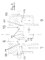
- the membrane-controlled two-stroke engine shown in FIG. 1 shows an additional one Intake device 1, which is located on an intake 6 between the carburetor 4 and Membrane housing 5, and their arrangement on the rear support channel 3. How shown, the engine is at the intake of fresh gas. Through everywhere equal negative pressure in the crankcase, in the flushing channels and additional suction device can be one in the additional suction device open membrane 2. In this process, the fresh gas comes directly from Carburetor via the additional suction device to the flushing slot. That through the Additional intake device bypassed fresh gas bypasses the crankcase and is not adversely heated.
- membrane-controlled intake device 1 penetrates the fresh gas bypassing the Crankcase 14 to the mouth area 23 of the support channel 3 and flushing channels 7, 8, 9, 10 and to the flushing slots 11 in the mouth areas 23 of these channels in front.
- This portion of fresh gas that bypasses the crankcase remains cold while that remaining fresh gas, which in a known manner via opening membranes 24 in Membrane housing 5 flows from the carburetor 4 into the crankcase 14, in the Crankcase warmed up.
- the fresh gas mixture introduced into the cylinder chamber has a lower average Temperature on than in conventional two-stroke engines, so that the degree of filling is raised and the risk of self-ignition of the compressed Fresh gas mixture reduced when the piston 13 moves upward again is.
- connection of the additional suction device on the rear Support channel 3 shown.
- the connection is such that that caused by the support channel Reverse irrigation is not affected.
- one of the suction devices ends 1 Fresh gas duct 22 leading to the support duct for cold fresh gas with low Distance from the flushing slot 11.
- the additional suction device has several Fresh gas channels 22 for cold fresh gas, cf. Figures 5 and 6.
- the Fresh gas channels branch behind the membrane housing 2 'and open into the rinsing channels 7, 8, 9, 10 in their mouth areas 23 at the end of the rinsing channels, as can be seen above all from FIG. 6.
- the rinsing channels and their mouth areas are arranged symmetrically to the cylinder axis 18.
- connection of the fresh gas lines are for cold Fresh gas at the rear support channel or the purge channels variable:
- they are in designed in each case in such a way that in the mouth area of the flushing channels when sucking in fresh gas from the carburetor bypassing the Crankcase can collect cold fresh gas, which then in front of the cylinder space heated fresh gas can flow from the crankcase.
Abstract
Bei kurbelgehäuse-gespülten Zweitaktverbrennungsmotoren wird das Frischgas durch das Kurbelgehäuse angesaugt und dort von der örtlichen Wärme aufgeheizt. Dies wirkt sich bekanntlich negativ auf die Füllung des Motors aus. Die zusätzliche Ansaugvorrichtung befördert kaltes, nicht aufgeheiztes Frischgas, direkt vom Vergaser zum Spülschlitz, verbessert somit die Füllung und setzt die Selbstzündungsgefahr herab. . Die zusätzliche Ansaugvorrichtung (siehe Figur 1) befindet sich auf dem Ansaugstutzen 6 zwischen Vergaser 4 und Membrangehäuse 5 und ist an allen Spülkanälen 7, 8, 9, 10 und am Stützkanal 3 angeschlossen. Da beim Ansaugen überall gleicher Unterdruck herrscht, öffnet sich die Membran 2 in der zusätzlichen Ansaugvorrichtung 1. So wird das Kurbelgehäuse umgangen. Ein Teil der Frischgase wird nicht negativ erhitzt und gelangt so, kalt, direkt zum Spülschlitz 11. Die zusätzliche Ansaugvorrrichtung eignet sich aufgrund der Füllungsverbesserung für jeden in Serie gebauten Zweitaktverbrennungsmotor, insbesondere aber für Rennsportmotoren. Sie kann an jedem Zweitaktverbrennungsmotor, sowohl an membrangesteuerten, als auch an schlitzgesteuerten oder plattendrehschiebergesteuerten Zweitaktverbrennungsmotoren, verwandt werden. <IMAGE>In the case of two-stroke internal combustion engines purged with crankcase, the fresh gas is drawn in through the crankcase and heated there by the local heat. As is well known, this has a negative effect on the filling of the engine. The additional intake device conveys cold, unheated fresh gas directly from the carburetor to the flushing slot, thus improving the charge and reducing the risk of auto-ignition. . The additional suction device (see FIG. 1) is located on the suction nozzle 6 between the carburetor 4 and the membrane housing 5 and is connected to all the flushing channels 7, 8, 9, 10 and to the support channel 3. Since the vacuum is the same everywhere during suction, the membrane 2 opens in the additional suction device 1. In this way, the crankcase is bypassed. Some of the fresh gases are not negatively heated and thus reach the flushing slot 11, cold, because of the improvement in filling, the additional intake device is suitable for any two-stroke internal combustion engine built in series, but especially for racing engines. It can be used on any two-stroke internal combustion engine, both on diaphragm-controlled, as well as on slot-controlled or plate rotary valve controlled two-stroke internal combustion engines. <IMAGE>
Description
Die Erfindung betrifft eine Ansaugvorrichtung eines kurbelgehäuse-gespülten Zweitaktverbrennungsmotors, bei dem ein Teil des im Vergaser erzeugten Brennstoff/Luftgemisches, im folgenden als Frischgas bezeichnet, unter Umgehung des Kurbelgehäuses in den Zylinderraum eingeführt wird.The invention relates to an intake device of a crankcase-purged Two-stroke internal combustion engine, in which a part of that generated in the carburetor Fuel / air mixture, hereinafter referred to as fresh gas, bypassing of the crankcase is inserted into the cylinder space.
Es ist bekannt, daß bei kurbelgehäuse-gespülten Zweitaktverbrennungsmotoren das Frischgas durch den im Kurbelgehäuse erzeugten Unterdruck angesaugt wird. Dadurch, daß sich Kurbelgehäuse und Kurbelwelle aufheizen, wird auch das Frischgas aufgeheizt, dehnt sich aus und verschlechtert die Füllung des Motors.It is known that in crankcase-purged two-stroke internal combustion engines Fresh gas is sucked in by the negative pressure generated in the crankcase. Because the crankcase and crankshaft heat up, that too Fresh gas heated up expands and deteriorates the filling of the engine.
Aus US-PS-4,194,470 ist es bekannt, bei einem Zweitaktmotor einen Teil des Frischgases nicht durch das Kurbelgehäuse, sondern in einer Umgehungsleitung gesondert in den Zylinderraum einzuleiten. Dieser Frischgasanteil kann sich daher nicht erwärmen und bleibt im Gegensatz zu dem durch das Kurbelgehäuse strömenden Frischgas kalt. Gemäß dieser Druckschrift wird der kalte Frischgasanteil in dem Zeitraum, in dem der Kolben im unteren Totpunkt steht, gesondert in den Zylinderraum eingeführt und zusammen mit Frischgas, das erwärmt aus dem Kurbelgehäuse zuströmt, im Zylinderraum komprimiert. Zum Einleiten des kalten Frischgases aus dem Vergaser wird dabei der Unterdruck im Zylinderraum ausgenutzt, der beim Ausströmen von verbranntem Abgas aus dem Zylinderraum bei offenem Auslaßschlitz entsteht. Bei derartigem Ansaugen des Frischgases ist mit Gemischverlusten zu rechnen. Ein Teil des noch unverbrannten Frischgases wird mit dem Abgas abgeführt werden. Nachteilig ist auch, daß der Anteil des kalt in den Zylinderraum einströmenden Frischgases nicht ausreichend dosierbar ist und erforderlichen Ansprüchen nicht genügt. From US-PS-4,194,470 it is known in a two-stroke engine part of Fresh gas not through the crankcase, but in a bypass line to be introduced separately into the cylinder chamber. This fresh gas portion can therefore does not heat up and remains in contrast to that through the crankcase flowing fresh gas cold. According to this document, the cold fresh gas content in the period in which the piston is at bottom dead center, separately in the Cylinder space introduced and together with fresh gas that warms up from the Crankcase flows in, compressed in the cylinder space. To initiate the cold Fresh gas from the carburetor becomes the negative pressure in the cylinder chamber exploited, which when burned exhaust gas flows out of the cylinder space open outlet slot is created. When the fresh gas is sucked in with Mixture losses to be expected. A part of the still unburned fresh gas is with the exhaust gas are discharged. Another disadvantage is that the proportion of cold in the Fresh gas flowing into the cylinder space is not sufficiently metered and necessary requirements are not sufficient.
Aufgabe der Erfindung ist es, Vorkehrungen zu treffen, um die Menge des einzuführenden kalten Frischgases optimieren zu können und das kalte Frischgas zugleich effektiv in den Zylinderraum einzuleiten.The object of the invention is to take precautions to the amount of to be able to optimize the cold fresh gas to be introduced and the cold fresh gas at the same time to effectively introduce into the cylinder space.
Gemäß der Erfindung wird diese Aufgabe bei einem Zweitaktmotor der vorgenannten Art dadurch gelöst, daß das einzuführende kalte, nicht aufgeheizte Frischgas von einer zusätzlichen Ansaugvorrichtung zum Spülschlitz am Zylinderraum geleitet wird. Mit "Spülschlitz" werden vom Motorfachmann die zum Zylinderraum hin offenen Mündungen der Spülkanäle bezeichnet, die zur Zufuhr von Frischgas dienen. Der kalte Frischgasanteil wird somit gemäß der Erfindung unmittelbar an der Mündungsstelle einer bereits vorhandenen Frischgas-Zufuhrleitung eingeführt und gelangt auf dem gleichen Wege in den Zylinderraum, wie das aufgeheizte Frischgas normaler Weise aus dem Kurbelgehäuse einströmt. Durch diesen Anschluß der zusätzlichen Ansaugvorrichtung an einem Spülschlitz eines Spülkanals wird in vorteilhafter Weise erreicht, daß beim Aufwärtsgang des Kolbens, bei dem bei einem kurbelgehäuse-gespülten Zweitaktmotor im gasdicht abgedichteten Kurbelgehäuse Unterdruck entsteht und Frischgas aus dem Vergaser in das Kurbelgehäuse angesaugt wird, infolge des erzeugten Unterdrucks auch die zusätzliche Ansaugvorrichtung, die mit den Spülkanälen und dem Kurbelgehäuse räumlich verbunden ist, aus dem Vergaser mit Frischgas gefüllt wird. Gemäß der Erfindung wird somit der das heiße Kurbelgehäuse umgehende und somit kalt bleibende Frischgasanteil zusammen mit dem wie bisher in das Kurbelgehäuse eingeführten übrigen Frischgas aus dem Vergaser angesaugt. Zum Ansaugen wird das vorhandene Ansaugsystem des Zweitaktmotors ausgenutzt, es kann - bis auf die zusätzlich anzubringende Ansaugvorrichtung - ohne Änderung beibehalten werden.According to the invention, this object is achieved in a two-stroke engine of the aforementioned Kind solved in that the cold, unheated fresh gas to be introduced by an additional suction device is directed to the flushing slot on the cylinder chamber. The engine specialist uses "flushing slot" to open the cylinder compartment Mouths of the purge channels referred to, which serve to supply fresh gas. The cold fresh gas content is thus according to the invention directly on the Mouth of an existing fresh gas supply line introduced and reaches the cylinder chamber in the same way as the heated fresh gas flows normally from the crankcase. Through this connection the additional suction device on a flushing slot of a flushing channel is in advantageously achieved that in the upward movement of the piston, in which at one Crankcase-flushed two-stroke engine in a gastight sealed crankcase Vacuum is created and fresh gas from the carburetor into the crankcase is sucked in, due to the negative pressure generated, the additional Suction device that spatially with the flushing channels and the crankcase is connected, from the carburetor is filled with fresh gas. According to the invention becomes the hot crankcase bypassing and thus remaining cold Fresh gas content together with that introduced into the crankcase as before remaining fresh gas drawn from the carburetor. It is used for suction existing intake system of the two-stroke engine is used, it can - except for the additional suction device to be attached - can be retained without change.
Bei einer Abwärtsbewegung des Kolbens strömt dann nach Öffnen des Spülschlitzes der kalte Frischgasanteil aus der zusätzlichen Ansaugvorrichtung unmittelbar in den Zylinderraum ein, bevor das übrige erwärmte Frischgas aus dem Kurbelgehäuse gegebenenfalls zusammen mit restlichem kalten Frischgas aus der zusätzlichen Ansaugvorrichtung in den Zylinderraum eingeführt wird. Dies kühlt Kolbenboden und Zylinderkopf. Das in den Zylinderraum einströmende kalte Frischgas wird so zum Betrieb des Zweitaktmotors effektiv genutzt. Insgesamt weist das zu komprimierende Frischgasgemisch eine niedrigere mittlere Temperatur auf, als bei bekannten Zweitaktmotoren. Der Füllgrad des Zylinderraums ist somit angehoben und die Gefahr einer Selbstzündung des Frischgasgemisches herabgesetzt. Die zugeführte kalte Frischgasmenge kann mittels der Ansaugvorrichtung vorgegeben werden, insbesondere durch Dimensionieren der Sammelräume für Frischgas in der Ansaugvorrichtung und durch Wahl ihrer Membranen.With a downward movement of the piston then flows after opening the flushing slot the cold fresh gas portion from the additional intake device directly into the Cylinder space before the remaining heated fresh gas from the crankcase optionally together with remaining cold fresh gas from the additional Suction device is inserted into the cylinder space. This cools the piston crown and Cylinder head. The cold fresh gas flowing into the cylinder chamber thus becomes Operation of the two-stroke engine used effectively. Overall, the one to be compressed Fresh gas mixture at a lower average temperature than in known Two-stroke engines. The degree of filling of the cylinder space is thus increased and the Risk of self-ignition of the fresh gas mixture is reduced. The fed cold fresh gas quantity can be specified using the suction device, in particular by dimensioning the collection rooms for fresh gas in the Suction device and by choosing their membranes.
Bevorzugt mündet die zusätzliche Ansaugvorrichtung im Mündungsbereich aller Spülkanäle des Zweitaktmotors.The additional suction device preferably opens into the mouth area of all Flush channels of the two-stroke engine.
Die mit der Erfindung erzielten Vorteile bestehen insbesondere darin, daß die Füllung des Motors verbessert wird und damit auch die Leistung des Motors. Die strömungsbedingt schlechter gefüllten Stellen der Spülkanäle im Zylinder können jetzt durch gezieltes Anbringen der zusätzlichen Ansaugvorrichtung nochmals besser gefüllt werden. Ein weiterer Vorteil besteht darin, daß der Kolbenboden und der Zylinderkopf besser gekühlt werden und somit die Gefahr der Selbstzündung (Detonation) insbesondere bei hochverdichteten Rennsportmotoren abgesenkt wird, womit der Motor gleichzeitig standfester wird. Die zusätzliche Ansaugvorrichtung kann bei allen Zweitaktverbrennungsmotoren, also sowohl schlitzgesteuerten, als auch membran- und drehschiebergesteuerten Zweitaktverbrennungsmotoren, angewandt werden.The advantages achieved with the invention are in particular that the filling of the engine is improved and thus the performance of the engine. The Places of the rinsing channels in the cylinder that are poorly filled due to the flow can now even better by attaching the additional suction device be filled. Another advantage is that the piston crown and the Cylinder head can be cooled better and thus the risk of auto-ignition (Detonation) is reduced in particular in the case of highly compressed racing engines, which makes the engine more stable at the same time. The additional suction device can with all two-stroke internal combustion engines, so both slot-controlled, as also diaphragm and rotary valve controlled two-stroke internal combustion engines, be applied.
Die Erfindung und weitere Ausgestaltungen der Erfindung werden anhand eines in der Zeichnung schematisch dargestellten Ausführungsbeispiels näher erläutert. Es zeigen im einzelnen:
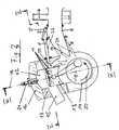
Figur 1- Membrangesteuerter Zweitaktmotor mit zusätzlicher Ansaugvorrichtung beim Ansaugen von Frischgas,
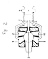
Figur 2- Seitliche Anordnung der zusätzlichen Ansaugvorrichtung an Spülkanälen und hinterem Stützkanal,
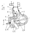
Figur 3- Schnitt durch Zylinderraum und Kurbelgehäuse eines
Zweitaktverbrennungsmotors mit zusätzlicher
Ansaugvorrichtung nach
Figur 1 gemäß Schnittlinie III/III nach Figur 5 bei Aufwärtsbewegung des Kolbens, Figur 4- Schnitt durch Zylinder und Kurbelgehäuse wie
Figur 3 bei Stellung des Kolbens im unteren Totpunkt, - Figur 5
- Schnitt durch Zylinder und Kurbelgehäuse gemäß
Schnittlinie V/V nach
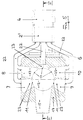
Figur 3. Figur 6- Ausschnitt des Zylinders gemäß Schnittlinie VI/VI nach
Figur 3 mit Verlauf der Spülkanäle im Zylinder.
- Figure 1
- Membrane-controlled two-stroke engine with additional intake device when drawing in fresh gas,
- Figure 2
- Lateral arrangement of the additional suction device on the flushing channels and rear support channel,
- Figure 3
- Section through cylinder space and crankcase of a two-stroke internal combustion engine with an additional intake device according to FIG. 1 according to section line III / III according to FIG. 5 when the piston moves upwards,
- Figure 4
- Section through cylinder and crankcase as in Figure 3 with the piston in bottom dead center,
- Figure 5
- Section through cylinder and crankcase according to section line V / V according to FIG. 3.
- Figure 6
- Section of the cylinder according to section line VI / VI of Figure 3 with the course of the rinsing channels in the cylinder.
Der in Figur 1 dargestellte membrangesteuerte Zweitaktmotor zeigt eine zusätzliche
Ansaugvorrichtung 1, die sich auf einem Ansaugstutzen 6 zwischen Vergaser 4 und
Membrangehäuse 5 befindet, und ihre Anordnung am hinteren Stützkanal 3. Wie
dargestellt, befindet sich der Motor beim Ansaugen von Frischgas. Durch den überall
gleich herrschenden Unterdruck im Kurbelgehäuse, in den Spülkanälen und der
zusätzlichen Ansaugvorrichtung kann sich eine in der zusätzlichen Ansaugvorrichtung
befindliche Membran 2 öffnen. Bei diesem Vorgang gelangt das Frischgas direkt vom
Vergaser über die zusätzliche Ansaugvorrichtung zum Spülschlitz. Das durch die
zusätzliche Ansaugvorrichtung angesaugte Frischgas umgeht so das Kurbelgehäuse
und wird nicht nachteilig aufgeheizt.The membrane-controlled two-stroke engine shown in FIG. 1 shows an additional one
Der in Figur 2 dargestellte Zylinder mit Ansaugstutzen 6, Vergaser 4 und zusätzlicher
Ansaugvorrichtung 1 zeigt die Anordnung der zusätzlichen Ansaugvorrichtung an
Spülkanälen 7, 8, 9, 10 und am hinteren Stützkanal 3.The cylinder shown in Figure 2 with
In Figuren 1 und 3 befindet sich Kolben 13 des Zweitaktmotors in Drehrichtung 20 der
Kurbelwelle 19 in seinem Aufwärtsweg. Dabei wird das im Zylinderraum 12
vorhandene Frischgas komprimiert und - infolge des erzeugten Unterdrucks im
Kurbelgehäuse 14 - zugleich Frischgas aus dem Vergaser 4 ins Kurbelgehäuse
angesaugt. Mit Frischgas füllt sich hierbei auch die zusätzliche Ansaugvorrichtung 1,
die, wie im Ausführungsbeispiel gezeigt, durch ihren Anschluß sowohl am hinteren
Stützkanal 3 als auch an den Spülkanälen 7, 8, 9, 10 räumlich mit dem Kurbelgehäuse
14 verbunden ist und somit unter Unterdruck steht, so daß sich die Membran 2 im
Membrangehäuse 2' am Eingang der Ansaugvorrichtung 1 öffnet. Über die somit
membrangesteuerte Ansaugvorrichtung 1 dringt das Frischgas unter Umgehung des
Kurbelgehäuses 14 bis zum Mündungsbereich 23 von Stützkanal 3 und Spülkanälen
7, 8, 9, 10 und zu den Spülschlitzen 11 in den Mündungsbereichen 23 dieser Kanäle
vor. Dieser Frischgasanteil, der das Kurbelgehäuse umgeht, bleibt kalt, während das
übrige Frischgas, das in bekannter Weise über sich öffnende Membranen 24 im
Membrangehäuse 5 aus dem Vergaser 4 ins Kurbelgehäuse 14 strömt, sich im
Kurbelgehäuse erwärmt.In Figures 1 and 3 there is
Nach Kompression des im Zylinderraum 12 vorhandenen Frischgases bei der
Aufwärtsbewegung des Kolbens 13 im Zylinder 17 und nach Zündung des
Frischgasgemisches mittels Zündkerze 21 bewegt sich der Kolben abwärts, gibt
dabei die Abgasleitung 15 zum Auslaß verbrannten Abgases frei und erhöht den
Druck im Kurbelgehäuse 14. In seiner unteren Stellung gibt der Kolben dann, wie in
Figur 4 gezeigt ist, den Spülschlitz 11 des hinteren Stützkanals 3 und im
Ausführungsbeispiel auch die Spülschlitze 11 der Spülkanäle 7,8,9,10 zum
Zylinderraum 12 hin frei. Durch die offenen Spülschlitze strömt das unter Druck
stehende Frischgas dann in den Zylinderraum ein. Es wird dabei zunächst das kalte
Frischgas aus der zusätzlichen Ansaugvorrichtung 1 eingeführt, anschließend das
erwärmte Frischgas aus dem Kurbelgehäuse 14. Dadurch, daß zuerst kaltes
Frischgas und im wesentlichen erst anschließend aufgeheiztes Frischgas in den
Zylinderraum 12 einströmt, ergibt sich eine sehr effektive Kühlung für Kolbenboden
und Zylinderkopf 16.After compression of the fresh gas present in the
Das in den Zylinderraum eingeführte Frischgasgemisch weist eine niedrigere mittlere
Temperatur auf als bei herkömmlichen Zweitaktmotoren, so daß der Füllgrad
angehoben ist und die Gefahr einer Selbstzündung des komprimierten
Frischgasgemisches bei erneuter Aufwärtsbewegung des Kolbens 13 herabgesetzt
ist.The fresh gas mixture introduced into the cylinder chamber has a lower average
Temperature on than in conventional two-stroke engines, so that the degree of filling
is raised and the risk of self-ignition of the compressed
Fresh gas mixture reduced when the
In Figuren 3 und 4 ist der Anschluß der zusätzlichen Ansaugvorrichtung am hinteren
Stützkanal 3 dargestellt. Der Anschluß ist derart, daß die vom Stützkanal bewirkte
Umkehrspülung nicht beeinträchtigt wird. Hierzu endet ein von der Ansaugvorrichtung
1 zum Stützkanal geführter Frischgaskanal 22 für kaltes Frischgas mit geringem
Abstand vom Spülschlitz 11. Die zusätzliche Ansaugvorrichtung weist mehrere
Frischgaskanäle 22 für kaltes Frischgas auf, vgl. Figuren 5 und 6. Die
Frischgaskanäle verzweigen sich hinter dem Membrangehäuse 2' und münden in
den Spülkanälen 7, 8, 9, 10 in ihren Mündungsbereichen 23 am Ende der Spülkanäle,
wie vor allem aus Figur 6 ersichtlich ist. Die Spülkanäle und ihre Mündungsbereiche
sind symmetrisch zur Zylinderachse 18 angeordnet. In Figures 3 and 4, the connection of the additional suction device on the
Die Erfindung ist selbstverständlich nicht auf das dargestellte Ausführungsbeispiel beschränkt. Insbesondere sind die Anschlüsse der Frischgasleitungen für kaltes Frischgas am hinteren Stützkanal oder den Spülkanälen variabel: Sie sind jedoch in jedem Falle derart gestaltet, daß sich im Mündungsbereich der Spülkanäle beim Ansaugen von Frischgas aus dem Vergaser unter Umgehung des Kurbelgehäuses kaltes Frischgas sammeln kann, das dann in den Zylinderraum vor erwärmtem Frischgas aus dem Kurbelgehäuse einströmen kann. The invention is of course not based on the illustrated embodiment limited. In particular, the connections of the fresh gas lines are for cold Fresh gas at the rear support channel or the purge channels variable: However, they are in designed in each case in such a way that in the mouth area of the flushing channels when sucking in fresh gas from the carburetor bypassing the Crankcase can collect cold fresh gas, which then in front of the cylinder space heated fresh gas can flow from the crankcase.
- zusätzliche Ansaugvorrichtungadditional suction device
- 11
- Membranmembrane
- 22nd
- MembrangehäuseMembrane housing
- 2'2 '
- hinterer Stützkanalrear support channel
- 33rd
- VergaserCarburetor
- 44th
- MembrangehäuseMembrane housing
- 55
- AnsaugstutzenIntake manifold
- 66
- SpülkanäleRinsing channels
- 7,8,9,107,8,9,10
- SpülschlitzFlushing slot
- 1111
- ZylinderraumCylinder space
- 1212th
- Kolbenpiston
- 1313
- KurbelgehäuseCrankcase
- 1414
- AbgasleitungExhaust pipe
- 1515
- ZylinderkopfCylinder head
- 1616
- Zylindercylinder
- 1717th
- ZylinderachseCylinder axis
- 1818th
- Kurbelwellecrankshaft
- 1919th
- DrehrichtungDirection of rotation
- 2020th
- Zündkerzespark plug
- 2121
- Frischgaskanal für kaltes FrischgasFresh gas duct for cold fresh gas
- 2222
- MündungsbereichMouth area
- 2323
- MembranenMembranes
- 2424th
Claims (6)
Applications Claiming Priority (2)
| Application Number | Priority Date | Filing Date | Title |
|---|---|---|---|
| DE19850244 | 1998-10-31 | ||
| DE19850244A DE19850244C2 (en) | 1998-10-31 | 1998-10-31 | Additional intake device for two-stroke internal combustion engines |
Publications (1)
| Publication Number | Publication Date |
|---|---|
| EP0997623A1 true EP0997623A1 (en) | 2000-05-03 |
Family
ID=7886268
Family Applications (1)
| Application Number | Title | Priority Date | Filing Date |
|---|---|---|---|
| EP99121386A Withdrawn EP0997623A1 (en) | 1998-10-31 | 1999-10-27 | Intake device for a two stroke internal combustion engine |
Country Status (3)
| Country | Link |
|---|---|
| EP (1) | EP0997623A1 (en) |
| JP (1) | JP2000136726A (en) |
| DE (2) | DE19850244C2 (en) |
Cited By (1)
| Publication number | Priority date | Publication date | Assignee | Title |
|---|---|---|---|---|
| US6634326B2 (en) | 2000-12-06 | 2003-10-21 | Dolmar, Gmbh | Two-stroke motor with fresh-gas supply and flange for a two-stroke motor |
Families Citing this family (5)
| Publication number | Priority date | Publication date | Assignee | Title |
|---|---|---|---|---|
| DE10009796B4 (en) * | 2000-03-01 | 2008-09-18 | Andreas Stihl Ag & Co. | Diesel internal-combustion engine diagnosing and/or controlling method, involves determining whether pressure difference of injection interval in opening phase and/or injection interval in closing phase exceeds preset value |
| DE10009793A1 (en) * | 2000-03-01 | 2001-09-06 | Stihl Maschf Andreas | 2-stroke engine with adjustable charge for chain saws etc. has overflow channels connected to air feed channels with adjustable throttles for different air flow volume in individual channels |
| DE10009621A1 (en) * | 2000-03-01 | 2001-09-06 | Stihl Maschf Andreas | Two-stroke engine with charge stratification |
| US7143725B1 (en) * | 2005-11-22 | 2006-12-05 | Lung Tan Hu | Dual six-stroke self-cooling internal combustion engine |
| NL1040344C2 (en) * | 2013-08-21 | 2015-02-24 | Vhm Van Haandel Motorparts B V | TWO-STROKE ENGINE BLOCK WITH INNOVATIVE CARTER, WITH TECHNICAL SOLUTIONS FOUND. THE CARTER IS CONSTRUCTED SO THAT THE CARBURETOR CAN BE HORIZONTALLY POSITIONED. THE ROTATION DIRECTION OF THE CRANKSHAFT IS REVERSED T.O.V. AN EXISTING ENGINE BLOCK. THE CRANKSHAFT ROTES THE SAME DIRECTION AS THE FLOW DIRECTION OF THE AIR-FUEL MIXTURE. THE AIR-FUEL MIXTURE FLOWS FROM THE CARBURETOR THROUGH A SEPARATE FLOW CHANNEL IN THE CARTER THROUGH THE CRANKSHAFT. AN INTERMEDIATE WHEEL IS NECESSARY AT THE INNOVATIVE CARTER. |
Citations (7)
| Publication number | Priority date | Publication date | Assignee | Title |
|---|---|---|---|---|
| US4194470A (en) * | 1978-03-13 | 1980-03-25 | Magner Richard W | Two-cycle internal combustion engine having boost port |
| JPS585424A (en) * | 1981-07-02 | 1983-01-12 | Nippon Clean Engine Res | Crank chamber compression 2-cycle internal combustion engine |
| US4469054A (en) * | 1983-05-19 | 1984-09-04 | Nippon Clean Engine Research Institute Co., Ltd. | Two-stroke internal-combustion engine |
| JPS60111019A (en) * | 1983-11-19 | 1985-06-17 | Nippon Clean Engine Res | Two-cycle internal-combustion engine |
| JPS60145416A (en) * | 1983-12-30 | 1985-07-31 | Nippon Clean Engine Res | Lamellar scavenging 2-cycle internal-combustion engine |
| JPS62113824A (en) * | 1985-11-13 | 1987-05-25 | Nippon Clean Engine Res | Intake scavenge system preceding air scavenge action for two-cycle internal combustion engine |
| EP0348828A2 (en) * | 1988-06-25 | 1990-01-03 | T&N TECHNOLOGY LIMITED | Pistons |
-
1998
- 1998-10-31 DE DE19850244A patent/DE19850244C2/en not_active Expired - Fee Related
-
1999
- 1999-10-27 DE DE29918886U patent/DE29918886U1/en not_active Expired - Lifetime
- 1999-10-27 EP EP99121386A patent/EP0997623A1/en not_active Withdrawn
- 1999-10-29 JP JP11309512A patent/JP2000136726A/en not_active Withdrawn
Patent Citations (7)
| Publication number | Priority date | Publication date | Assignee | Title |
|---|---|---|---|---|
| US4194470A (en) * | 1978-03-13 | 1980-03-25 | Magner Richard W | Two-cycle internal combustion engine having boost port |
| JPS585424A (en) * | 1981-07-02 | 1983-01-12 | Nippon Clean Engine Res | Crank chamber compression 2-cycle internal combustion engine |
| US4469054A (en) * | 1983-05-19 | 1984-09-04 | Nippon Clean Engine Research Institute Co., Ltd. | Two-stroke internal-combustion engine |
| JPS60111019A (en) * | 1983-11-19 | 1985-06-17 | Nippon Clean Engine Res | Two-cycle internal-combustion engine |
| JPS60145416A (en) * | 1983-12-30 | 1985-07-31 | Nippon Clean Engine Res | Lamellar scavenging 2-cycle internal-combustion engine |
| JPS62113824A (en) * | 1985-11-13 | 1987-05-25 | Nippon Clean Engine Res | Intake scavenge system preceding air scavenge action for two-cycle internal combustion engine |
| EP0348828A2 (en) * | 1988-06-25 | 1990-01-03 | T&N TECHNOLOGY LIMITED | Pistons |
Non-Patent Citations (4)
| Title |
|---|
| PATENT ABSTRACTS OF JAPAN vol. 007, no. 079 (M - 204) 31 March 1983 (1983-03-31) * |
| PATENT ABSTRACTS OF JAPAN vol. 009, no. 264 (M - 423) 22 October 1985 (1985-10-22) * |
| PATENT ABSTRACTS OF JAPAN vol. 009, no. 311 (M - 436) 7 December 1985 (1985-12-07) * |
| PATENT ABSTRACTS OF JAPAN vol. 011, no. 330 (M - 636) 28 October 1987 (1987-10-28) * |
Cited By (1)
| Publication number | Priority date | Publication date | Assignee | Title |
|---|---|---|---|---|
| US6634326B2 (en) | 2000-12-06 | 2003-10-21 | Dolmar, Gmbh | Two-stroke motor with fresh-gas supply and flange for a two-stroke motor |
Also Published As
| Publication number | Publication date |
|---|---|
| DE19850244C2 (en) | 2001-02-08 |
| DE29918886U1 (en) | 2000-01-20 |
| DE19850244A1 (en) | 1999-06-24 |
| JP2000136726A (en) | 2000-05-16 |
Similar Documents
| Publication | Publication Date | Title |
|---|---|---|
| DE3212910C2 (en) | ||
| DE10127242A1 (en) | Intake air separation system for an internal combustion engine | |
| DE3338870A1 (en) | DEVICE FOR CONTROLLING THE CHANGE OF CHARGE IN INTERNAL COMBUSTION ENGINES | |
| DD144941A1 (en) | COMBUSTION ENGINE | |
| DE2914489A1 (en) | TWO-STROKE COMBUSTION ENGINE | |
| DE2308127B2 (en) | Two-stroke internal combustion engine with two or three compression chambers | |
| DE4410934A1 (en) | Crankcase compression two-stroke engine | |
| DE2844309C2 (en) | Two-stroke internal combustion engine | |
| DE8021214U1 (en) | Internal combustion engine intake assembly | |
| EP0997623A1 (en) | Intake device for a two stroke internal combustion engine | |
| DE2027883A1 (en) | Internal combustion engine | |
| DE10157579A1 (en) | Aspiration system for two stroke engine has a fresh air duct from the carburettor connected to the exhaust side of the cylinder to sweep burnt gasses out of the cylinder ahead of the fresh mixture charge | |
| DE2245417A1 (en) | FUEL METERING SYSTEM FOR TWO-STROKE COMBUSTION MACHINES | |
| DE2617245C2 (en) | Exhaust gas cleaning system for a four-stroke internal combustion engine | |
| DE2230234C3 (en) | Spark-ignited four-stroke internal combustion engine | |
| DE2450956C3 (en) | Internal combustion engine | |
| DE660108C (en) | Air-flushed carburetor two-stroke internal combustion engine | |
| DE577740C (en) | Compressed air internal combustion engine | |
| DE3929124A1 (en) | INTERNAL COMBUSTION ENGINE WITH A CHARGING UNIT | |
| DE3024043A1 (en) | INTAKE SYSTEM FOR AN INTERNAL COMBUSTION ENGINE | |
| DE60200240T2 (en) | TWO-STROKE INTERNAL COMBUSTION ENGINE USING A PNEUMATICALLY SUPPORTED FUEL DIRECT INJECTION | |
| DE2261180A1 (en) | FOUR-STROKE COMBUSTION ENGINE | |
| DE2440354A1 (en) | TWO-STROKE GASOLINE ENGINE | |
| DE3042624C2 (en) | Air or mixture compressing single or multiple rotary piston internal combustion engine | |
| DE2743495A1 (en) | Swirl chamber for IC engine - has suction operated inlet valve in sparking plug holder in cylinder head |
Legal Events
| Date | Code | Title | Description |
|---|---|---|---|
| PUAI | Public reference made under article 153(3) epc to a published international application that has entered the european phase |
Free format text: ORIGINAL CODE: 0009012 |
|
| AK | Designated contracting states |
Kind code of ref document: A1 Designated state(s): AT BE CH CY DE DK ES FI FR GB GR IE IT LI LU MC NL PT SE |
|
| AX | Request for extension of the european patent |
Free format text: AL;LT;LV;MK;RO;SI |
|
| AKX | Designation fees paid | ||
| STAA | Information on the status of an ep patent application or granted ep patent |
Free format text: STATUS: THE APPLICATION IS DEEMED TO BE WITHDRAWN |
|
| 18D | Application deemed to be withdrawn |
Effective date: 20001104 |