EP0348828A2 - Pistons - Google Patents
Pistons Download PDFInfo
- Publication number
- EP0348828A2 EP0348828A2 EP89111424A EP89111424A EP0348828A2 EP 0348828 A2 EP0348828 A2 EP 0348828A2 EP 89111424 A EP89111424 A EP 89111424A EP 89111424 A EP89111424 A EP 89111424A EP 0348828 A2 EP0348828 A2 EP 0348828A2
- Authority
- EP
- European Patent Office
- Prior art keywords
- piston
- engine
- cavity
- cylinder
- passage
- Prior art date
- Legal status (The legal status is an assumption and is not a legal conclusion. Google has not performed a legal analysis and makes no representation as to the accuracy of the status listed.)
- Withdrawn
Links
Images
Classifications
-
- F—MECHANICAL ENGINEERING; LIGHTING; HEATING; WEAPONS; BLASTING
- F02—COMBUSTION ENGINES; HOT-GAS OR COMBUSTION-PRODUCT ENGINE PLANTS
- F02F—CYLINDERS, PISTONS OR CASINGS, FOR COMBUSTION ENGINES; ARRANGEMENTS OF SEALINGS IN COMBUSTION ENGINES
- F02F3/00—Pistons
- F02F3/28—Other pistons with specially-shaped head
-
- F—MECHANICAL ENGINEERING; LIGHTING; HEATING; WEAPONS; BLASTING
- F02—COMBUSTION ENGINES; HOT-GAS OR COMBUSTION-PRODUCT ENGINE PLANTS
- F02B—INTERNAL-COMBUSTION PISTON ENGINES; COMBUSTION ENGINES IN GENERAL
- F02B17/00—Engines characterised by means for effecting stratification of charge in cylinders
-
- F—MECHANICAL ENGINEERING; LIGHTING; HEATING; WEAPONS; BLASTING
- F02—COMBUSTION ENGINES; HOT-GAS OR COMBUSTION-PRODUCT ENGINE PLANTS
- F02B—INTERNAL-COMBUSTION PISTON ENGINES; COMBUSTION ENGINES IN GENERAL
- F02B75/00—Other engines
- F02B75/02—Engines characterised by their cycles, e.g. six-stroke
-
- F—MECHANICAL ENGINEERING; LIGHTING; HEATING; WEAPONS; BLASTING
- F02—COMBUSTION ENGINES; HOT-GAS OR COMBUSTION-PRODUCT ENGINE PLANTS
- F02B—INTERNAL-COMBUSTION PISTON ENGINES; COMBUSTION ENGINES IN GENERAL
- F02B1/00—Engines characterised by fuel-air mixture compression
- F02B1/02—Engines characterised by fuel-air mixture compression with positive ignition
- F02B1/04—Engines characterised by fuel-air mixture compression with positive ignition with fuel-air mixture admission into cylinder
-
- F—MECHANICAL ENGINEERING; LIGHTING; HEATING; WEAPONS; BLASTING
- F02—COMBUSTION ENGINES; HOT-GAS OR COMBUSTION-PRODUCT ENGINE PLANTS
- F02B—INTERNAL-COMBUSTION PISTON ENGINES; COMBUSTION ENGINES IN GENERAL
- F02B75/00—Other engines
- F02B75/02—Engines characterised by their cycles, e.g. six-stroke
- F02B2075/022—Engines characterised by their cycles, e.g. six-stroke having less than six strokes per cycle
- F02B2075/025—Engines characterised by their cycles, e.g. six-stroke having less than six strokes per cycle two
-
- F—MECHANICAL ENGINEERING; LIGHTING; HEATING; WEAPONS; BLASTING
- F02—COMBUSTION ENGINES; HOT-GAS OR COMBUSTION-PRODUCT ENGINE PLANTS
- F02B—INTERNAL-COMBUSTION PISTON ENGINES; COMBUSTION ENGINES IN GENERAL
- F02B2275/00—Other engines, components or details, not provided for in other groups of this subclass
- F02B2275/40—Squish effect
-
- Y—GENERAL TAGGING OF NEW TECHNOLOGICAL DEVELOPMENTS; GENERAL TAGGING OF CROSS-SECTIONAL TECHNOLOGIES SPANNING OVER SEVERAL SECTIONS OF THE IPC; TECHNICAL SUBJECTS COVERED BY FORMER USPC CROSS-REFERENCE ART COLLECTIONS [XRACs] AND DIGESTS
- Y02—TECHNOLOGIES OR APPLICATIONS FOR MITIGATION OR ADAPTATION AGAINST CLIMATE CHANGE
- Y02T—CLIMATE CHANGE MITIGATION TECHNOLOGIES RELATED TO TRANSPORTATION
- Y02T10/00—Road transport of goods or passengers
- Y02T10/10—Internal combustion engine [ICE] based vehicles
- Y02T10/12—Improving ICE efficiencies
Definitions
- the present invention relates to pistons for internal combustion engines and particularly to pistons for 2-stroke engines.
- a further aspect of the problem relates to the need to avoid an autocatalytic reacton wherein low fuel octane quality, excessive engine temperatures, inadequate scavenging or wrong air to fuel ratio can lead to damaging high frequency detonation of pockets of end gas (so called 'combustion knock'); and where detonation shock waves sweep through the charge, causing slowing of flame speed, sharply increasing local heat transfer and turbulence values, leading to serious damage.
- the requirement for a slightly concave, flat or slightly convex crown is to ensure that the vital scavenging gas flows are not significantly impaired.
- a further object of the present invention is to achieve stable, regular combustion at low revolution speeds and light load, thereby improving fuel economy, torque, engine flexibility and hydrocarbon emissions.
- a two-stroke internal combustion engine comprises a cylinder for receiving a piston, a piston in said cylinder, a combustion chamber having ignition means, means for inducing a combustible air and fuel charge into the engine, scavenge-port means for transferring the combustible charge into the combustion space above the piston, exhaust-port means for disposing of exhaust gases, the engine being characterised by having auxiliary-port means for the controlled admission of air into a cavity within the structure of the piston crown when the piston is passing through the lower dead centre region of its travel.
- the opening of the auxiliary-port means is controlled by a valve which modulates the flow of air to the cavity within the structure of the piston crown by allowing less air to pass as the engine speed and load rises.
- a valve may be a relatively simple air proportioning valve activated by a slide in the engine carburettor intake or may be an electronically controlled valve depending upon engine speed, for example.
- a piston for the first aspect comprising a crown portion and a skirt portion and wherein the crown portion includes a cavity lying beneath the crown surface but within the crown structure, said cavity having a first passage adapted to co-operate with an auxiliary air induction port in the cylinder wall of a two-stroke engine and a second passage communicating with the swept cylinder volume of the engine.
- the piston may have at least two piston rings one being positioned above said first passage and the second being positioned below said first passage.
- the cavity and second passage form part of a system transiently resonant with the compressed combustion gas volume of the cylinder near TDC as will be described below.
- the radial width of the second passage when in the form of an arcuate slot to match geometrically the compression space 'squish' zone, may lie in the range from 1.5 to 2.5mm for most engines. This dimensional range may, however, be exceeded for some engines.
- the length of the arcuate slot may vary depending upon the specific engine and the compression space geometry at TDC.
- the engine comprises a cylinder head 12 having a spark-plug 14, a cylinder liner 16 and a cylinder jacket 18.
- a piston 20 is contained within the cylinder 16.
- the engine also has the usual connecting rod, crankshaft and crankcase (all not shown).
- the cylinder liner 16 and jacket 18 have cooperating apertures defining an exhaust port 22, inlet port 24 for the main combustible charge and an auxiliary air inlet port 26.
- the inlet port 24 communicates with a carburettor 29 and throttle valve 31.
- the liner 16 also has scavenge ports 28 to transfer the induced charge from the crankcase (not shown) to the swept cylinder volume 30.
- a proportioning valve 32 controls admission of air to the auxiliary air port 26.
- the piston 20 has two piston rings 34 and 36.
- the top ring 34 is near to the crown surface 38 to reduce the top piston ring land crevice volume to a minimum.
- Within the structure of the piston crown is a cavity 40 which has a first passage 42 which communicates in the region of inner or bottom dead centre with the auxiliary air inlet port 26.
- a second passage 44 in the shape of an arcuate slot communicates with the swept cylinder volume 30.
- the passage 44 has a radial width of about 1.8mm and an arcuate extent in plan of about 90 o .
- the second piston ring 36 lies below the first passage 42.
- the cavity 40 and first passage 42 are shown in Figure 3 by dashed lines.
- the piston 20 is shown in the bottom dead centre position.
- air/fuel mixture is admitted to the engine cylinder via the throttle valve 31, the normal induction port 24 and scavenge ports 28.
- Auxiliary air is also admitted via the air proportioning valve 32, the air port 26, cavity 40 and communicating passage 44, to the cylinder.
- This auxiliary air supply is proportioned by means of the proportioning valve 32 relative to the main fuel/air mixture supply so as to have a maximum value at small throttle openings, progressively decreasing to a minimum value at or near wide open throttle.
- the latter may require local contouring to avoid excessive damping and permit adequate exchange of the transient pressure waves between the resonant cavity and the combustion gas around top dead centre.
- the main combustion and scavenging events are not adversely affected, and turbulent air motion within the piston cavity raises local heat transfer coefficients to avoid excessive piston temperatures.
Landscapes
- Engineering & Computer Science (AREA)
- Chemical & Material Sciences (AREA)
- Combustion & Propulsion (AREA)
- Mechanical Engineering (AREA)
- General Engineering & Computer Science (AREA)
- Combustion Methods Of Internal-Combustion Engines (AREA)
- Pistons, Piston Rings, And Cylinders (AREA)
Abstract
Description
- The present invention relates to pistons for internal combustion engines and particularly to pistons for 2-stroke engines.
- The characteristic irregular firing of gasoline fuelled, spark ignited two-stroke engines under light load is well known, as is poor torque and relatively heavy fuel consumption under these conditions.
- A further aspect of the problem relates to the need to avoid an autocatalytic reacton wherein low fuel octane quality, excessive engine temperatures, inadequate scavenging or wrong air to fuel ratio can lead to damaging high frequency detonation of pockets of end gas (so called 'combustion knock'); and where detonation shock waves sweep through the charge, causing slowing of flame speed, sharply increasing local heat transfer and turbulence values, leading to serious damage.
- The use of pistons having fixed external cavities in the crown region are known. Such external cavities form part of a resonant system with the combustion chamber. An engine with a piston having such an external cavity is described in US 4370959. The external cavity, however, is formed by a cap on the piston crown and which cap significantly interferes with the gas flow during the induction and exhaust phases.
- It is an object of the present invention to provide a two stroke engine and a piston having a slightly concave, flat or slightly convex crown and which piston does not suffer from the above disadvantages. The requirement for a slightly concave, flat or slightly convex crown is to ensure that the vital scavenging gas flows are not significantly impaired.
- A further object of the present invention is to achieve stable, regular combustion at low revolution speeds and light load, thereby improving fuel economy, torque, engine flexibility and hydrocarbon emissions.
- According to a first aspect of the present invention a two-stroke internal combustion engine comprises a cylinder for receiving a piston, a piston in said cylinder, a combustion chamber having ignition means, means for inducing a combustible air and fuel charge into the engine, scavenge-port means for transferring the combustible charge into the combustion space above the piston, exhaust-port means for disposing of exhaust gases, the engine being characterised by having auxiliary-port means for the controlled admission of air into a cavity within the structure of the piston crown when the piston is passing through the lower dead centre region of its travel.
- Preferably the opening of the auxiliary-port means is controlled by a valve which modulates the flow of air to the cavity within the structure of the piston crown by allowing less air to pass as the engine speed and load rises. Such a valve may be a relatively simple air proportioning valve activated by a slide in the engine carburettor intake or may be an electronically controlled valve depending upon engine speed, for example.
- According to a second aspect of the present invention there is provided a piston for the first aspect, the piston comprising a crown portion and a skirt portion and wherein the crown portion includes a cavity lying beneath the crown surface but within the crown structure, said cavity having a first passage adapted to co-operate with an auxiliary air induction port in the cylinder wall of a two-stroke engine and a second passage communicating with the swept cylinder volume of the engine.
- Preferably the piston may have at least two piston rings one being positioned above said first passage and the second being positioned below said first passage.
- The cavity and second passage form part of a system transiently resonant with the compressed combustion gas volume of the cylinder near TDC as will be described below.
- The radial width of the second passage, when in the form of an arcuate slot to match geometrically the compression space 'squish' zone, may lie in the range from 1.5 to 2.5mm for most engines. This dimensional range may, however, be exceeded for some engines. The length of the arcuate slot may vary depending upon the specific engine and the compression space geometry at TDC.
- In order that the present invention may be more fully understood an example will now be described by way of illustration only with reference to the accompanying drawings, of which:
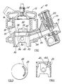
- Figure 1 shows a part cross section in elevation of an engine, piston and carburettor according to the present invention;
- Figure 2 shows a cross section in more detail of the piston of Figure 1; and
- Figure 3 shows a plan view of the crown surface of the piston of Figure 2.
- Referring now to the drawings and where the same features are denoted by common reference numerals:
- Part of a loop scavenged two-stroke gasoline engine is shown generally at 10. The engine comprises a
cylinder head 12 having a spark-plug 14, acylinder liner 16 and acylinder jacket 18. Apiston 20 is contained within thecylinder 16. The engine also has the usual connecting rod, crankshaft and crankcase (all not shown). Thecylinder liner 16 andjacket 18 have cooperating apertures defining anexhaust port 22,inlet port 24 for the main combustible charge and an auxiliaryair inlet port 26. Theinlet port 24 communicates with acarburettor 29 andthrottle valve 31. Theliner 16 also hasscavenge ports 28 to transfer the induced charge from the crankcase (not shown) to theswept cylinder volume 30. Aproportioning valve 32 controls admission of air to theauxiliary air port 26. Thepiston 20 has twopiston rings top ring 34 is near to thecrown surface 38 to reduce the top piston ring land crevice volume to a minimum. Within the structure of the piston crown is acavity 40 which has afirst passage 42 which communicates in the region of inner or bottom dead centre with the auxiliaryair inlet port 26. Asecond passage 44 in the shape of an arcuate slot communicates with theswept cylinder volume 30. Thepassage 44 has a radial width of about 1.8mm and an arcuate extent in plan of about 90o. Thesecond piston ring 36 lies below thefirst passage 42. Thecavity 40 andfirst passage 42 are shown in Figure 3 by dashed lines. Thepiston 20 is shown in the bottom dead centre position. - In operation air/fuel mixture is admitted to the engine cylinder via the
throttle valve 31, thenormal induction port 24 andscavenge ports 28. Auxiliary air is also admitted via theair proportioning valve 32, theair port 26,cavity 40 and communicatingpassage 44, to the cylinder. - This auxiliary air supply is proportioned by means of the
proportioning valve 32 relative to the main fuel/air mixture supply so as to have a maximum value at small throttle openings, progressively decreasing to a minimum value at or near wide open throttle. Such an augmentation of the air/fuel charge by supplementary air in this manner has a large stabilising effect on successive combustion events particularly under conditions of light load or low revolution speed, by raising the notional volumetric efficiency and the compression ratio, whilst decreasing the charge dilution with burnt gas from a prior working cycle. - Any air not directly short circuited to the cylinder from the
cavity 40 during the air transfer phase, will tend to remain in the cavity during the compression stroke of the piston. Upon approaching the top centre position, a sharp fronted pressure wave spontaneously excited by the ignition/combustion sequence, bucks and drives the air in thecavity 40 into transient resonance. - The resonant cavity system is proportioned such that its natural frequency is approximately equal to the fundamental knock frequency of the cylinder/cylinder head combination of the engine in question, and thus approximately obeys the characteristics of a Helmholtz resonator:

A = the area of thenecked passage 44 square to the flow
L = the effective throat coupling length of thepassage 44
V = the resonant volume of thecavity 40
K = a modifying constant to broaden frequency response band. - Because of the close proximity of the cavity to the cylinder head, the latter may require local contouring to avoid excessive damping and permit adequate exchange of the transient pressure waves between the resonant cavity and the combustion gas around top dead centre.
- Any incipient "knock waves" in the cylinder are thus presented with a counter wave system of approximately identical frequency, resulting in a rapid decay of both the resonant and knock waves. This artificially induced damping greatly reduces the likelihood of detonation damage.
- The main combustion and scavenging events are not adversely affected, and turbulent air motion within the piston cavity raises local heat transfer coefficients to avoid excessive piston temperatures.
Claims (9)
Applications Claiming Priority (2)
| Application Number | Priority Date | Filing Date | Title |
|---|---|---|---|
| GB8815183A GB2220031B (en) | 1988-06-25 | 1988-06-25 | Pistons |
| GB8815183 | 1988-06-25 |
Publications (2)
| Publication Number | Publication Date |
|---|---|
| EP0348828A2 true EP0348828A2 (en) | 1990-01-03 |
| EP0348828A3 EP0348828A3 (en) | 1990-05-02 |
Family
ID=10639378
Family Applications (1)
| Application Number | Title | Priority Date | Filing Date |
|---|---|---|---|
| EP89111424A Withdrawn EP0348828A3 (en) | 1988-06-25 | 1989-06-21 | Pistons |
Country Status (3)
| Country | Link |
|---|---|
| US (1) | US4969425A (en) |
| EP (1) | EP0348828A3 (en) |
| GB (1) | GB2220031B (en) |
Cited By (5)
| Publication number | Priority date | Publication date | Assignee | Title |
|---|---|---|---|---|
| EP0997621A1 (en) * | 1998-10-30 | 2000-05-03 | Komatsu Zenoah Co. | Stratified scavenging two-cycle engine |
| EP0997623A1 (en) * | 1998-10-31 | 2000-05-03 | Guido Förster | Intake device for a two stroke internal combustion engine |
| EP1221545A3 (en) * | 1998-05-11 | 2002-07-31 | Ricardo Consulting Engineers Limited | Carburettors for two-stroke engines |
| RU2230913C2 (en) * | 2000-01-14 | 2004-06-20 | Актиеболагет Электролюкс | Two-stroke internal combustion engine |
| RU2246013C2 (en) * | 2000-04-27 | 2005-02-10 | Актиеболагет Электролюкс | Two-stroke internal combustion engine |
Families Citing this family (27)
| Publication number | Priority date | Publication date | Assignee | Title |
|---|---|---|---|---|
| GB2319297B (en) * | 1996-11-14 | 2000-04-12 | T & N Technology Ltd | Piston with chamber |
| JPH10325321A (en) * | 1997-05-24 | 1998-12-08 | Honda Motor Co Ltd | Two-cycle internal combustion engine |
| SE513446C2 (en) * | 1999-01-19 | 2000-09-11 | Electrolux Ab | Crankcase coil internal combustion engine of two stroke type |
| US7082910B2 (en) | 1999-01-19 | 2006-08-01 | Aktiebolaget Electrolux | Two-stroke internal combustion engine |
| SE0000095L (en) | 2000-01-14 | 2001-07-15 | Electrolux Ab | Damper for regulating auxiliary air for two-stroke internal combustion engines |
| JP2003519749A (en) | 2000-01-14 | 2003-06-24 | アクティエボラゲット エレクトロラックス | Two-stroke internal combustion engine |
| CN100386511C (en) | 2000-04-27 | 2008-05-07 | 哈斯科瓦那股份公司 | two-stroke internal combustion engine |
| US6708958B1 (en) | 2002-10-04 | 2004-03-23 | Electrolux Home Products, Inc. | Air valve mechanism for two-cycle engine |
| JP4061252B2 (en) * | 2003-08-11 | 2008-03-12 | ザマ・ジャパン株式会社 | Two-cycle engine carburetor |
| US7299894B2 (en) * | 2004-07-02 | 2007-11-27 | Anest Iwata Corporation | Acoustic fluid machine |
| US20060011411A1 (en) * | 2004-07-15 | 2006-01-19 | Anest Iwata Corporation | Acoustic compressor |
| CN100430596C (en) * | 2004-08-04 | 2008-11-05 | 阿耐斯特岩田株式会社 | Acoustic fluid machine |
| US7735834B2 (en) * | 2005-12-07 | 2010-06-15 | Fev Engine Technology, Inc. | Two-stroke internal combustion engine with oil ring |
| US7895978B2 (en) * | 2006-09-12 | 2011-03-01 | Soundstarts, Inc. | Non-polluting two-stroke engine with air-cooled piston |
| US10526953B2 (en) | 2017-03-30 | 2020-01-07 | Quest Engines, LLC | Internal combustion engine |
| US10590813B2 (en) | 2017-03-30 | 2020-03-17 | Quest Engines, LLC | Internal combustion engine |
| US10598285B2 (en) | 2017-03-30 | 2020-03-24 | Quest Engines, LLC | Piston sealing system |
| US10465629B2 (en) | 2017-03-30 | 2019-11-05 | Quest Engines, LLC | Internal combustion engine having piston with deflector channels and complementary cylinder head |
| US11041456B2 (en) | 2017-03-30 | 2021-06-22 | Quest Engines, LLC | Internal combustion engine |
| US10753308B2 (en) | 2017-03-30 | 2020-08-25 | Quest Engines, LLC | Internal combustion engine |
| US10590834B2 (en) | 2017-03-30 | 2020-03-17 | Quest Engines, LLC | Internal combustion engine |
| US10989138B2 (en) | 2017-03-30 | 2021-04-27 | Quest Engines, LLC | Internal combustion engine |
| JP6894981B2 (en) | 2017-04-28 | 2021-06-30 | クエスト エンジンズ,エルエルシー | Variable volume chamber device |
| US10883498B2 (en) | 2017-05-04 | 2021-01-05 | Quest Engines, LLC | Variable volume chamber for interaction with a fluid |
| US10808866B2 (en) | 2017-09-29 | 2020-10-20 | Quest Engines, LLC | Apparatus and methods for controlling the movement of matter |
| US10753267B2 (en) | 2018-01-26 | 2020-08-25 | Quest Engines, LLC | Method and apparatus for producing stratified streams |
| US11134335B2 (en) | 2018-01-26 | 2021-09-28 | Quest Engines, LLC | Audio source waveguide |
Family Cites Families (14)
| Publication number | Priority date | Publication date | Assignee | Title |
|---|---|---|---|---|
| US1535433A (en) * | 1925-04-28 | Gtjstave a | ||
| US1046359A (en) * | 1908-04-02 | 1912-12-03 | Winton Motor Carriage Co | Two-cycle engine. |
| US1483619A (en) * | 1921-12-02 | 1924-02-12 | Jr George W Smith | Internal-combustion engine |
| US1527166A (en) * | 1923-04-05 | 1925-02-24 | Bezu Maurice | Two-cycle internal-combustion engine |
| FR1002432A (en) * | 1946-09-30 | 1952-03-06 | Feeding device for two-stroke engines | |
| FR1022403A (en) * | 1949-07-06 | 1953-03-04 | Miller & Company Ltd H | Improvements to internal combustion engines |
| FR1042370A (en) * | 1951-09-21 | 1953-10-30 | Two-stroke engine | |
| JPS5333048Y2 (en) * | 1974-12-07 | 1978-08-15 | ||
| US4016839A (en) * | 1975-02-07 | 1977-04-12 | Morton Clyde M | Method for fueling combustion engines |
| JPS5934848B2 (en) * | 1975-07-08 | 1984-08-24 | ヤマハ発動機株式会社 | Crank chamber compression type 2-stroke engine |
| DE2630284A1 (en) * | 1975-07-16 | 1977-02-03 | A C Engines | COMBUSTION MACHINERY |
| US4167930A (en) * | 1978-07-24 | 1979-09-18 | Avco Corporation | Internal combustion engine with sustained power stroke |
| GB2057562B (en) * | 1979-08-31 | 1983-05-25 | Toyota Motor Co Ltd | Two-stroke cycle petrol engine |
| US4370959A (en) * | 1980-05-30 | 1983-02-01 | Avco Corporation | Two stroke cycle engine with sustained power stroke |
-
1988
- 1988-06-25 GB GB8815183A patent/GB2220031B/en not_active Expired - Lifetime
-
1989
- 1989-06-21 EP EP89111424A patent/EP0348828A3/en not_active Withdrawn
- 1989-06-21 US US07/369,737 patent/US4969425A/en not_active Expired - Fee Related
Cited By (6)
| Publication number | Priority date | Publication date | Assignee | Title |
|---|---|---|---|---|
| EP1221545A3 (en) * | 1998-05-11 | 2002-07-31 | Ricardo Consulting Engineers Limited | Carburettors for two-stroke engines |
| EP0997621A1 (en) * | 1998-10-30 | 2000-05-03 | Komatsu Zenoah Co. | Stratified scavenging two-cycle engine |
| EP0997623A1 (en) * | 1998-10-31 | 2000-05-03 | Guido Förster | Intake device for a two stroke internal combustion engine |
| RU2230913C2 (en) * | 2000-01-14 | 2004-06-20 | Актиеболагет Электролюкс | Two-stroke internal combustion engine |
| RU2232907C2 (en) * | 2000-01-14 | 2004-07-20 | Актиеболагет Электролюкс | Two-stroke internal combustion engine |
| RU2246013C2 (en) * | 2000-04-27 | 2005-02-10 | Актиеболагет Электролюкс | Two-stroke internal combustion engine |
Also Published As
| Publication number | Publication date |
|---|---|
| US4969425A (en) | 1990-11-13 |
| GB2220031A (en) | 1989-12-28 |
| GB8815183D0 (en) | 1988-08-03 |
| EP0348828A3 (en) | 1990-05-02 |
| GB2220031B (en) | 1992-07-01 |
Similar Documents
| Publication | Publication Date | Title |
|---|---|---|
| US4969425A (en) | Piston with a resonant cavity | |
| US20220003155A1 (en) | Method of injecting ammonia fuel into a reciprocating engine | |
| US3934562A (en) | Two-cycle engine | |
| US4312305A (en) | Two-stroke cycle gasoline engine | |
| US5390634A (en) | Internal combustion engine having high performance combustion chamber | |
| US4211189A (en) | Internal combustion engine with dual induction system and more particularly to combustion chamber design thereof | |
| EP0476010B1 (en) | Reciprocating piston engine with pumping and power cylinders | |
| LV11365A (en) | Ignition engine | |
| US4480597A (en) | Two-stroke cycle gasoline engine | |
| US4276858A (en) | Two-cycle internal combustion engine | |
| US4821687A (en) | Two-stroke engine | |
| RU2001113446A (en) | INTERNAL COMBUSTION ENGINE | |
| US4307687A (en) | Internal combustion engines | |
| US4586465A (en) | Internal combustion engine | |
| US4023541A (en) | Combustion chamber for internal-combustion engine | |
| JP2792308B2 (en) | In-cylinder injection type internal combustion engine | |
| US4549508A (en) | Two-cycle internal combustion engine | |
| US2744506A (en) | Two-stroke uniflow-scavenged internal combustion engine | |
| US5881687A (en) | Two-stroke internal combustion engine | |
| CA1072450A (en) | Stratified charge four-stroke engine | |
| US4893596A (en) | Combustion chamber for spark ignited engine | |
| GB2232718A (en) | Two-stroke engine exhaust control | |
| JPH09280053A (en) | 2-cycle engine | |
| US2776650A (en) | Internal combustion engines | |
| JPH05240047A (en) | Internal combustion engine |
Legal Events
| Date | Code | Title | Description |
|---|---|---|---|
| PUAI | Public reference made under article 153(3) epc to a published international application that has entered the european phase |
Free format text: ORIGINAL CODE: 0009012 |
|
| AK | Designated contracting states |
Kind code of ref document: A2 Designated state(s): DE FR IT |
|
| PUAL | Search report despatched |
Free format text: ORIGINAL CODE: 0009013 |
|
| AK | Designated contracting states |
Kind code of ref document: A3 Designated state(s): DE FR IT |
|
| 17P | Request for examination filed |
Effective date: 19900825 |
|
| 17Q | First examination report despatched |
Effective date: 19911104 |
|
| STAA | Information on the status of an ep patent application or granted ep patent |
Free format text: STATUS: THE APPLICATION IS DEEMED TO BE WITHDRAWN |
|
| 18D | Application deemed to be withdrawn |
Effective date: 19930914 |