EP0997607A2 - Vakuumbehhälter zur Behandlung des Bohrkleins von Öl- und Gasbohrlöchern - Google Patents
Vakuumbehhälter zur Behandlung des Bohrkleins von Öl- und Gasbohrlöchern Download PDFInfo
- Publication number
- EP0997607A2 EP0997607A2 EP99308577A EP99308577A EP0997607A2 EP 0997607 A2 EP0997607 A2 EP 0997607A2 EP 99308577 A EP99308577 A EP 99308577A EP 99308577 A EP99308577 A EP 99308577A EP 0997607 A2 EP0997607 A2 EP 0997607A2
- Authority
- EP
- European Patent Office
- Prior art keywords
- tank
- outlet header
- hopper
- cuttings
- frame
- Prior art date
- Legal status (The legal status is an assumption and is not a legal conclusion. Google has not performed a legal analysis and makes no representation as to the accuracy of the status listed.)
- Granted
Links
Images


Classifications
-
- B—PERFORMING OPERATIONS; TRANSPORTING
- B63—SHIPS OR OTHER WATERBORNE VESSELS; RELATED EQUIPMENT
- B63B—SHIPS OR OTHER WATERBORNE VESSELS; EQUIPMENT FOR SHIPPING
- B63B27/00—Arrangement of ship-based loading or unloading equipment for cargo or passengers
- B63B27/24—Arrangement of ship-based loading or unloading equipment for cargo or passengers of pipe-lines
- B63B27/25—Arrangement of ship-based loading or unloading equipment for cargo or passengers of pipe-lines for fluidised bulk material
-
- B—PERFORMING OPERATIONS; TRANSPORTING
- B63—SHIPS OR OTHER WATERBORNE VESSELS; RELATED EQUIPMENT
- B63B—SHIPS OR OTHER WATERBORNE VESSELS; EQUIPMENT FOR SHIPPING
- B63B27/00—Arrangement of ship-based loading or unloading equipment for cargo or passengers
- B63B27/29—Other loading or unloading equipment involving a continuous action, not provided in groups B63B27/22 - B63B27/28
-
- B—PERFORMING OPERATIONS; TRANSPORTING
- B63—SHIPS OR OTHER WATERBORNE VESSELS; RELATED EQUIPMENT
- B63B—SHIPS OR OTHER WATERBORNE VESSELS; EQUIPMENT FOR SHIPPING
- B63B27/00—Arrangement of ship-based loading or unloading equipment for cargo or passengers
- B63B27/30—Arrangement of ship-based loading or unloading equipment for transfer at sea between ships or between ships and off-shore structures
- B63B27/34—Arrangement of ship-based loading or unloading equipment for transfer at sea between ships or between ships and off-shore structures using pipe-lines
-
- B—PERFORMING OPERATIONS; TRANSPORTING
- B63—SHIPS OR OTHER WATERBORNE VESSELS; RELATED EQUIPMENT
- B63B—SHIPS OR OTHER WATERBORNE VESSELS; EQUIPMENT FOR SHIPPING
- B63B35/00—Vessels or similar floating structures specially adapted for specific purposes and not otherwise provided for
- B63B35/44—Floating buildings, stores, drilling platforms, or workshops, e.g. carrying water-oil separating devices
-
- E—FIXED CONSTRUCTIONS
- E21—EARTH DRILLING; MINING
- E21B—EARTH DRILLING, e.g. DEEP DRILLING; OBTAINING OIL, GAS, WATER, SOLUBLE OR MELTABLE MATERIALS OR A SLURRY OF MINERALS FROM WELLS
- E21B21/00—Methods or apparatus for flushing boreholes, e.g. by use of exhaust air from motor
- E21B21/06—Arrangements for treating drilling fluids outside the borehole
- E21B21/063—Arrangements for treating drilling fluids outside the borehole by separating components
- E21B21/065—Separating solids from drilling fluids
- E21B21/066—Separating solids from drilling fluids with further treatment of the solids, e.g. for disposal
-
- E—FIXED CONSTRUCTIONS
- E21—EARTH DRILLING; MINING
- E21B—EARTH DRILLING, e.g. DEEP DRILLING; OBTAINING OIL, GAS, WATER, SOLUBLE OR MELTABLE MATERIALS OR A SLURRY OF MINERALS FROM WELLS
- E21B41/00—Equipment or details not covered by groups E21B15/00 - E21B40/00
- E21B41/005—Waste disposal systems
-
- B—PERFORMING OPERATIONS; TRANSPORTING
- B63—SHIPS OR OTHER WATERBORNE VESSELS; RELATED EQUIPMENT
- B63B—SHIPS OR OTHER WATERBORNE VESSELS; EQUIPMENT FOR SHIPPING
- B63B25/00—Load-accommodating arrangements, e.g. stowing, trimming; Vessels characterised thereby
- B63B25/02—Load-accommodating arrangements, e.g. stowing, trimming; Vessels characterised thereby for bulk goods
-
- B—PERFORMING OPERATIONS; TRANSPORTING
- B63—SHIPS OR OTHER WATERBORNE VESSELS; RELATED EQUIPMENT
- B63G—OFFENSIVE OR DEFENSIVE ARRANGEMENTS ON VESSELS; MINE-LAYING; MINE-SWEEPING; SUBMARINES; AIRCRAFT CARRIERS
- B63G8/00—Underwater vessels, e.g. submarines; Equipment specially adapted therefor
- B63G8/42—Towed underwater vessels
- B63G2008/425—Towed underwater vessels for transporting cargo, e.g. submersible barges for fluid cargo
Definitions
- the present invention relates to oil and gas well drilling and more particularly to the handling of cuttings that are generated during oil and gas well drilling activity. Even more particularly, the present invention relates to an improved vacuum tank apparatus for use in handling cuttings that are generated during oil and gas well exploration.
- the tank has a specially configured hopper that communicates with an outlet header that enables air to be injected during the discharge of cuttings from the tank.
- a drill bit In the drilling of oil and gas wells, a drill bit is used to dig many thousands of feet into the earth's crust.
- Oil rigs typically employ a derrick that extends above the well drilling platform and which can support joint after joint of drill pipe connected end to end during the drilling operation.
- additional pipe joints are added to the ever lengthening "string" or "drill string”.
- the drill pipe or drill string thus comprises a plurality of joints of pipe, each of which has an internal, longitudinally extending bore for carrying fluid drilling mud from the well drilling platform through the drill string and to a drill bit supported at the lower or distal end of the drill string.
- Drilling mud lubricates the drill bit and carries away well cuttings generated by the drill bit as it digs deeper.
- the cuttings are carried in a return flow stream of drilling mud through the well annulus and back to the well drilling platform at the earth's surface.
- the drilling mud reaches the surface, it is contaminated with small pieces of shale and rock which are known in the industry as well cuttings or drill cuttings.
- shale shakers have in the past been separated from the reusable drilling mud with commercially available separators that are know as "shale shakers".
- Other solids separators include mud cleaners and centrifuge. Some shale shakers are designed to filter coarse material from the drilling mud while other shale shakers arc designed to remove finer particles from the well drilling mud.
- the drilling mud is returned to a mud pit where it can be supplemented and/or treated prior to transmission back into the well bore via the drill string and to the drill bit to repeat the process.
- Drill cuttings contain not only the mud product which would contaminate the surrounding environment, but also can contain oil that is particularly hazardous to the environment, especially when drilling in a marine environment.
- Safeguard Disposal Systems, Inc. of Lafayette, Louisiana has manufactured, sold, and used publicly a cuttings disposal tank that includes hatch openings into which oil well cuttings can be placed.
- These prior art tanks also have attachments for enabling lift lines to be affixed to the tank so that it can be transported to and from offshore platforms and emptied when full. Further examples of these tanks are shown in one or more of the following United States Patents: 5,564,509; 5,402,857; Des. 337,809; and Des. 296,027.
- U.S. Patents 5,564,509 and 5,402,857 are incorporated herein by reference.
- the present invention provides and improved vacuum tank apparatus that can be used to vacuum drill cuttings on an oil and gas well drilling rig through an open top hatch portion of the apparatus and then to discharge those cuttings through an outlet header using suction applied to the outlet header as well as compressed injected air that is transmitted to the outlet header.
- the apparatus includes a frame having a plurality of comers reinforced by structural comer columns, a generally horizontally extended base that includes a plurality of base perimeter beams, and an upper end portion of the frame that includes a plurality of upper perimeter beams. The columns are structurally interconnected to both the upper perimeter beams and the base of the frame.
- a shaped hopper is supported by the frame internally of the perimeter beams.
- the hopper includes and interior and sidewalls that are comprised of a plurality of inclined sidewall sections, each inclined wall section including an upper end portion that connects to the frame at the perimeter beams and a lower end portion that extends to another lower end portion of another inclined wall section.
- the two lower end portions of the inclined wall sections that are joined meet at an outlet header at the bottom of the hopper.
- This outlet header is mated to the lower end portions of the inclined wall sections and includes a discharge outlet for discharging material from the hopper interior via the outlet header.
- the top wall of the hopper has multiple hatches including a first hatch near a first perimeter beam and a second hatch next to another perimeter beam that is parallel to the first perimeter beam.
- the outlet header includes opposed open end portions that are fittings for directing fluid flow.
- One of the end portions is an air inlet for injecting air into the outlet header.
- the other end portion of the outlet header defines a fitting for connecting a suction line thereto.
- a secondary air fitting for enhanced cleanout and material transfer can be provided at the discharge fitting.
- the outlet header thus preferably comprises a longitudinally extended trough portion with an open top that communicates with the interior of the hopper.
- a pair of opposed end portions of the trough have fittings for attaching flow lines to the outlet header.
- the outlet header thus defines a closed structure with the lower end portion of the hopper and the fittings so that a vacuum can be held on the tank when the outlet header is not being used.
- the outlet header preferably provides valves at each end portion next to the two fittings so that the flow of air into the outlet header can be valved. Additionally, the discharge of solid material from the outlet header can also be valved.
- the apparatus of the present invention eliminates the dangerous and messy practices of lifting and/or tipping the tank frame on an oil rig in order to empty the tank contents.
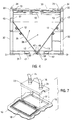
- the inclined walls of the hopper remove any need to tip or lift the tank during emptying.
- the hopper is configured to completely empty of material using a vacuum and without tipping or lifting thus eliminating a crane or cranes.
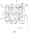
- FIGS 1-4 show the preferred embodiment of the apparatus of the present invention designated generally by the numeral 10 in Figures 1-4.
- Vacuum tank apparatus 10 is supported by a structural frame 11.
- the frame 11 holds a hopper 35 that is comprised of a plurality of hopper walls 12,13,14,15.
- a vibrator motor 80 can be affixed to one or more of the walls 12-15 to enhance setting of material within hopper 35 interior 38.
- the hopper 35 also includes a top plate 16 that carries a large hatch 17 and a small hatch 18. Each of the hatches 17, 18 respectively covers large opening 36 and small opening 37 respectively. Large hatch 17 is preferably used to dump material from the interior 38 of hopper 35 if desired.
- Top plate 16 that seals the hopper 35 at its upper end portion so that a vacuum can be pulled on the interior 38 of hopper 35.
- An outlet fitting 19 carries rupture disk 20.
- the outlet fitting 19 can include a pair of spaced apart flanges 21, 22 as shown in Figure 7.
- Fitting 19 is mounted on tank outlet opening 23.
- An additional fitting is provided at elbow 24 that communicates with opening 26 in top plate 16.
- the elbow 24 carries a ball valve 25 that can be opened and closed.
- Each of the hatches 17, 18 is mounted to the top plate 16 using hinges 27, 28 respectively.
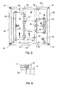
- a closure 29, 30 can be respectively provided for each hatch 17, 18 in the form of a cammed rod such as the rods 39, 40 shown in Figure 3.
- ring nuts and bolts can be used to close hatches 17, 18.
- Frame 11 is comprised of a plurality of base beams 31, column beams 32 and upper perimeter beams 33 as shown in Figures 1-4. These respective beams 31, 33, and column 32 form a rectangular block-like enclosure that protects hopper 35 during transportation.
- the base perimeter beams 31 can additionally be provided with plate for decking if desired.
- Left and right sockets 41, 42 define receptacles for fork lift tines at each perimeter beam 31 so that the apparatus 10 of the present invention can be lifted and transported using a fork lift if desired.
- Each of the column beams 32 occupies a comer of the frame 11 as shown in Figure 1-4.
- Each column beam 32 provides a stacking pin 34 at its upper end portion as showing in Figures 1-4 and 7.
- a correspondingly shaped socket under each column 32 at a perimeter beam 31 receives a stacking pin 34 when one tank apparatus 10 is stacked upon another tank 10.
- Lifting eyes 79 and slings can be attached to tank apparatus 10 for enabling a crane to lift the apparatus 10 during transfer to and from the drilling rig.
- the frame 11 can also includes additional intermediate horizontal beams 43 and vertical beams 44 that define an interface in between selected ones of the base beams 31, column beams 32 and upper perimeter beams 33.
- the intermediate perimeter beams 43 are generally parallel to and below upper perimeter beams 33.
- Each intermediate beam 43 connects to and spans between two columns 32 as shown in Figures 1,2 and 4.
- hopper walls 12, 13, 14, 15 At least two of these walls 12, 13 (and preferably all four walls 12-15) converge to form a connection with outlet header 50.
- Stiffners 77 can be welded to the walls 12, 13, 14, 15 for strengthening them.
- the walls 12, 13, 14, 15 each include inclined sections in between beams 31 and 43.
- the hopper 35 is thus shaped to enable complete emptying and discharge of drill cuttings and like material using a source of vacuum and without having to tip or lift the tank.
- the present invention eliminates the need for manual labor to shovel or scrape material to header 50.
- Each of the walls 12, 13, 14, 15 has a vertical section between beams 43 and 32.
- Outlet header 50 is shaped to facilitate discharge of material contained in hopper 35, shown in figures 1, 2, 4, 5, 8, 9, and 10.
- the outlet header includes a channel section 46 that is connected to the lower edge 47 of wall 12 of hopper 35 and to the lower edge 48 of wall 13 of hopper 35 as shown particularly in figures 4 and 5.
- the channel section provides a U - shaped trough in transverse cross section.
- the upper edges 49, 51 of channel section 49 are connected (e.g. welded) to the lower edges 47, 48 of sides 12, 13 of hopper 35.
- an inlet fitting 52 is provided at wall 15 of hopper 35 for injecting air under pressure.
- the fitting 52 can be a cylindrically shaped member having a central longitudinal bore with a central longitudinal axis that aligns with the central longitudinal axis 54 of channel section 49.
- Valve 55 can be positioned on the inlet 56 side of fitting 52 for closing the flow via fitting 52 to channel section 49. Upstream of valve 55 is a quick connect member that enables an air hose to quickly be connected to the assembly of fitting 52, valve 55 and quick connect member 57.
- compressed pressurized air can be injected into header 50 for assisting in the movement of material that flows by gravity from hopper interior 38 to a discharge hose 81 and then to a second vessel 82.
- a second vessel 82 can be a cuttings collection and disposal tank such as shown and described in my prior U.S. Patent Nos. 5,564,509 and 5,402,857. This flow of pressurized air and material is indicated by arrows 58 in figures 1 and 8-10.
- outlet fitting 59 is attached to the interface of wall 14 and channel member 49.
- the outlet fitting 59 can include a pair of pipe sections 60, 61 that form an angle of about 45 degrees as shown in figure 9.
- a cleanout plug 62 can be provided on fitting 59.
- a valve such 63 as a ball valve or butterfly valve can be provided for closing the flow of material from channel section 49 to the exterior of hopper 35 when the hopper is subjected to a vacuum.
- Valve 63 can be mounted between flanges 64, 65.
- a spool piece 66 with an open ended bore 70 can be fitted to flange 65 for transmitting material from hopper interior 38 via fitting 59 to a suction hose line 78.
- Fitting 71 on spool piece 66 can be used to couple an air line to the spool piece 66 as an additional means of moving material into discharge line 80 that is being removed from hopper 35 via outlet header 50.
- the spool piece comprises larger diameter section 67, transition section 68 and smaller diameter section 69.
- the outlet header 50 is closed by shutting valves 55 and 63. Drill cuttings can then be suctioned into the interior 38 of hopper 35 via one of the openings 36, 37 in top plate 16. This can be accomplished for example using a plate 72 attached to a selected opening 36 or 37 in the top plate of hopper 35 as shown in figure 7.
- Plate 72 has fittings 73, 74 for quick coupling and connecting respective inlet and outlet hoses 75, 76 to plate 72 when the hopper 35 is to be subjected to a vacuum.
- the inlet hose 75 is a suction hose for intake of drill cuttings.
- the discharge hose 76 connects to a vacuum source.
- Such a vacuum arrangement for vacuum of drill cuttings to a collection tank is shown and described in my prior U.S. patents 5,402,857 and 5,564,509 each of which is hereby incorporated herein by reference.
- drill cuttings are delivered to a cuttings receiving area (not shown) after having been separated from the well drilling fluid to enable the fluid to be recycled.
- An intake portion (not shown) of the inlet hose 75 is arranged at the receiving area to suction the drill cuttings and deliver them to the hopper 35 when a vacuum is created in the hopper 35, for example by connecting the outlet hose 76 to a vacuum source such as a blower with the air inlet valve 52 and cuttings outlet valve 59 closed. Liquids and solids may be prevented from entering the blower or similar power source by positioning a separating vessel in at least one of the vacuum lines, for example outlet hose 76.
- the flow velocity in the suction line 75 is in the range 100 to 300 feet per second with a vacuum of between about 16 to 25 inches of mercury. These are examples of typical values of the flow and vacuum and it will be understood that these are subject to variation according to the requirements for optimum performance of the invention in a given application.
- the cuttings are discharged from the hopper 35 and transferred to vessel 82 via line 81 when the outlet valve 59 is opened.
- the air inlet valve 52 may be opened to connect a source of pressurised air to the upstream end of the manifold 50. In this way, the cuttings are displaced towards the downstream end of the manifold 50 where the outlet valve 59 is connected.
- discharge of cuttings from the hopper 35 may be assisted by suction in the line 81 by connecting an air line to the spool piece 66.
- the present invention provides apparatus and method for use in handling cuttings generated during drilling operations that avoids or reduces the problems associated with the prior art. It will be understood, however, that the foregoing embodiments are presented by way of example only and that the scope of the invention is to be limited only by the following claims.
Applications Claiming Priority (2)
| Application Number | Priority Date | Filing Date | Title |
|---|---|---|---|
| US182623 | 1998-10-29 | ||
| US09/182,623 US6179070B1 (en) | 1994-02-17 | 1998-10-29 | Vacuum tank for use in handling oil and gas well cuttings |
Publications (3)
| Publication Number | Publication Date |
|---|---|
| EP0997607A2 true EP0997607A2 (de) | 2000-05-03 |
| EP0997607A3 EP0997607A3 (de) | 2001-05-30 |
| EP0997607B1 EP0997607B1 (de) | 2005-07-20 |
Family
ID=22669299
Family Applications (1)
| Application Number | Title | Priority Date | Filing Date |
|---|---|---|---|
| EP99308577A Expired - Lifetime EP0997607B1 (de) | 1998-10-29 | 1999-10-29 | Vakuumbehhälter zur Behandlung des Bohrkleins von Öl- und Gasbohrlöchern |
Country Status (8)
| Country | Link |
|---|---|
| US (1) | US6179070B1 (de) |
| EP (1) | EP0997607B1 (de) |
| AT (1) | ATE299985T1 (de) |
| AU (1) | AU762623B2 (de) |
| CA (1) | CA2287606C (de) |
| DE (1) | DE69926194T8 (de) |
| DK (1) | DK0997607T3 (de) |
| NO (1) | NO319329B1 (de) |
Cited By (28)
| Publication number | Priority date | Publication date | Assignee | Title |
|---|---|---|---|---|
| GB2375786A (en) * | 1998-06-11 | 2002-11-27 | Apollo Services Uk Ltd | Drill cuttings distribution system with vacuum lines and a solids displacement pump |
| WO2003095789A1 (en) * | 2002-05-09 | 2003-11-20 | Transfer Systems International | Container for handling material |
| WO2009137724A1 (en) * | 2008-05-07 | 2009-11-12 | Reddoch Jeffrey A | Method and apparatus for efficient handling of drill cuttings |
| EP2481881A3 (de) * | 2011-01-28 | 2016-01-27 | Michael James | Vakuumgestützter Bohrkleintrockner und Handhabungsvorrichtung |
| WO2016085349A1 (en) * | 2014-11-26 | 2016-06-02 | Esea As | A method and device for discharging particulate material |
| EP2874916A4 (de) * | 2012-07-23 | 2016-06-22 | Oren Technologies Llc | Stützmittelausgabesystem und behälter zur verwendung in solch einem stützmittelausgabesystem |
| US9624030B2 (en) | 2014-06-13 | 2017-04-18 | Oren Technologies, Llc | Cradle for proppant container having tapered box guides |
| USRE46381E1 (en) | 2012-11-02 | 2017-05-02 | Oren Technologies, Llc | Proppant vessel base |
| US9643774B2 (en) | 2011-12-21 | 2017-05-09 | Oren Technologies, Llc | Proppant storage vessel and assembly thereof |
| US9656799B2 (en) | 2012-07-23 | 2017-05-23 | Oren Technologies, Llc | Method of delivering, storing, unloading, and using proppant at a well site |
| US9670752B2 (en) | 2014-09-15 | 2017-06-06 | Oren Technologies, Llc | System and method for delivering proppant to a blender |
| US9676554B2 (en) | 2014-09-15 | 2017-06-13 | Oren Technologies, Llc | System and method for delivering proppant to a blender |
| US9682815B2 (en) | 2011-12-21 | 2017-06-20 | Oren Technologies, Llc | Methods of storing and moving proppant at location adjacent rail line |
| US9718610B2 (en) | 2012-07-23 | 2017-08-01 | Oren Technologies, Llc | Proppant discharge system having a container and the process for providing proppant to a well site |
| US9758081B2 (en) | 2012-07-23 | 2017-09-12 | Oren Technologies, Llc | Trailer-mounted proppant delivery system |
| USRE46576E1 (en) | 2013-05-17 | 2017-10-24 | Oren Technologies, Llc | Trailer for proppant containers |
| US9796319B1 (en) | 2013-04-01 | 2017-10-24 | Oren Technologies, Llc | Trailer assembly for transport of containers of proppant material |
| USRE46590E1 (en) | 2013-05-17 | 2017-10-31 | Oren Technologies, Llc | Train car for proppant containers |
| US9809381B2 (en) | 2012-07-23 | 2017-11-07 | Oren Technologies, Llc | Apparatus for the transport and storage of proppant |
| USRE46613E1 (en) | 2012-11-02 | 2017-11-28 | Oren Technologies, Llc | Proppant vessel |
| US9845210B2 (en) | 2016-01-06 | 2017-12-19 | Oren Technologies, Llc | Conveyor with integrated dust collector system |
| USRE46645E1 (en) | 2013-04-05 | 2017-12-26 | Oren Technologies, Llc | Trailer for proppant containers |
| US9862551B2 (en) | 2012-07-23 | 2018-01-09 | Oren Technologies, Llc | Methods and systems to transfer proppant for fracking with reduced risk of production and release of silica dust at a well site |
| USRE47162E1 (en) | 2012-11-02 | 2018-12-18 | Oren Technologies, Llc | Proppant vessel |
| US10226720B2 (en) | 2010-10-12 | 2019-03-12 | Cubility As | Cleaning device for separating hydrocarbons from solid particles |
| USD847489S1 (en) | 2012-09-24 | 2019-05-07 | Sandbox Logistics, Llc | Proppant container |
| US10518828B2 (en) | 2016-06-03 | 2019-12-31 | Oren Technologies, Llc | Trailer assembly for transport of containers of proppant material |
| US11873160B1 (en) | 2014-07-24 | 2024-01-16 | Sandbox Enterprises, Llc | Systems and methods for remotely controlling proppant discharge system |
Families Citing this family (35)
| Publication number | Priority date | Publication date | Assignee | Title |
|---|---|---|---|---|
| GB9913909D0 (en) * | 1999-06-16 | 1999-08-18 | Clyde Pneumatic Conveying Limi | Pneumatic conveying |
| GB0121353D0 (en) * | 2001-09-04 | 2001-10-24 | Rig Technology Ltd | Improvements in or relating to transport of waste materials |
| US7040418B2 (en) | 2001-11-02 | 2006-05-09 | M-I L.L.C. | Proppant recovery system |
| US6681874B2 (en) | 2002-01-23 | 2004-01-27 | Drill Cuttings Technology, L.L.C. | Method and apparatus for removing fluids from drill cuttings |
| GB2423781B (en) * | 2003-03-19 | 2007-03-28 | Varco Int | Apparatus and method for moving drilled cuttings |
| US6936092B2 (en) * | 2003-03-19 | 2005-08-30 | Varco I/P, Inc. | Positive pressure drilled cuttings movement systems and methods |
| US7493969B2 (en) | 2003-03-19 | 2009-02-24 | Varco I/P, Inc. | Drill cuttings conveyance systems and methods |
| PT1718839E (pt) * | 2004-01-29 | 2009-07-06 | Gjerdrum As Ing | Sistema, reservatório e unidade de evacuação para o transporte dos detritos de perfuração não tratados |
| GB0409318D0 (en) * | 2004-04-27 | 2004-06-02 | Its Drilling Services Ltd | Material transportation apparatus and method |
| US7983813B2 (en) * | 2004-10-29 | 2011-07-19 | Bose Corporation | Active suspending |
| US8095268B2 (en) * | 2004-10-29 | 2012-01-10 | Bose Corporation | Active suspending |
| US7506702B1 (en) * | 2004-12-30 | 2009-03-24 | Coastal Boat Rentals, Inc. | Method and apparatus for disposal of cuttings |
| US7753126B2 (en) * | 2005-11-26 | 2010-07-13 | Reddoch Sr Jeffrey A | Method and apparatus for vacuum collecting and gravity depositing drill cuttings |
| US7503406B2 (en) * | 2006-01-27 | 2009-03-17 | Halliburton Energy Services, Inc. | Method for processing drilling cuttings in an oil recovery operation |
| BRPI0709999A2 (pt) * | 2006-04-05 | 2011-08-02 | Baker Hughes Inc | sistema de transferência de fragmentos de rocha de perfuração e métodos relacionados |
| NO327436B1 (no) * | 2006-04-25 | 2009-06-29 | Cubility As | Fluidbehandlingssystem samt fremgangsmate ved anvendelse av samme |
| US8607894B2 (en) * | 2006-12-08 | 2013-12-17 | M-I Llc | Offshore thermal treatment of drill cuttings fed from a bulk transfer system |
| US8074738B2 (en) * | 2006-12-08 | 2011-12-13 | M-I L.L.C. | Offshore thermal treatment of drill cuttings fed from a bulk transfer system |
| EA016117B1 (ru) * | 2007-07-24 | 2012-02-28 | Эм-Ай ЭлЭлСи | Питающий бункер для поршневых насосов |
| US7962261B2 (en) * | 2007-11-12 | 2011-06-14 | Bose Corporation | Vehicle suspension |
| US8529160B2 (en) * | 2008-02-19 | 2013-09-10 | Steven Richard Ambriz | Bulk abrasive hopper |
| US7886850B2 (en) * | 2008-10-10 | 2011-02-15 | National Oilwell Varco, L.P. | Drilling fluid screening systems |
| US8123046B2 (en) * | 2008-10-23 | 2012-02-28 | Michael David Billeaud | Method and apparatus for separating and removing fluids from drill cuttings |
| NO339717B1 (no) | 2013-12-02 | 2017-01-23 | Cubility As | Sikteapparat og framgangsmåte ved bruk av samme |
| US10589287B2 (en) * | 2015-07-10 | 2020-03-17 | NGL Solids Solutions, LLC | Systems and methods for oil field solid waste processing for re-injection |
| US9925572B2 (en) | 2015-07-10 | 2018-03-27 | NGL Solids Solutions, LLC | Devices, systems, and processes for cleaning the interiors of frac tanks |
| US9656308B2 (en) | 2015-07-10 | 2017-05-23 | NGL Solids Solutions, LLC | Systems and processes for cleaning tanker truck interiors |
| CN109398602B (zh) * | 2017-08-15 | 2021-09-10 | 上海船厂船舶有限公司 | 用于钻井船的高压空气瓶组件的安装方法 |
| CN110424927B (zh) * | 2019-08-02 | 2022-06-03 | 山东省地质矿产勘查开发局八〇一水文地质工程地质大队 | 一种配合于旋挖机的卸料装置及方法 |
| US11911732B2 (en) | 2020-04-03 | 2024-02-27 | Nublu Innovations, Llc | Oilfield deep well processing and injection facility and methods |
| US11396419B1 (en) * | 2021-08-06 | 2022-07-26 | Magtech Alaska, LLC | Cold steel slurry box device |
| US11772884B2 (en) | 2021-08-06 | 2023-10-03 | Ryan Peterkin | Pressure vessel device |
| CA3095009A1 (en) | 2020-10-02 | 2022-04-02 | Magtec Alaska, LLC | Heated slurry transport system |
| US11739599B2 (en) * | 2020-10-21 | 2023-08-29 | BKG Industries, LLC | Proppant recovery unit |
| US20230042517A1 (en) * | 2021-08-06 | 2023-02-09 | Ryan Peterkin | Transportable Slurry Box Method of Use |
Citations (3)
| Publication number | Priority date | Publication date | Assignee | Title |
|---|---|---|---|---|
| GB2064979A (en) * | 1979-12-14 | 1981-06-24 | Svenska Flaektfabriken Ab | Extraction systems for particulate waste materials |
| US5104525A (en) * | 1991-05-13 | 1992-04-14 | Roderick James R | Portable self-contained water remediation package |
| WO1998016717A1 (en) * | 1996-10-15 | 1998-04-23 | M-I L.L.C. | Oil and gas well cuttings disposal system with continuous vacuum operation for sequentially filling disposal tanks |
Family Cites Families (23)
| Publication number | Priority date | Publication date | Assignee | Title |
|---|---|---|---|---|
| US1125413A (en) | 1912-04-18 | 1915-01-19 | Chester J Van Doren | Pneumatic apparatus for transferring material. |
| US2803501A (en) | 1954-02-25 | 1957-08-20 | Kennett C Kelly | Apparatus for raising gravel from ground level to roof level |
| US3400819A (en) | 1964-09-18 | 1968-09-10 | Mobil Oil Corp | Method and apparatus for particle segregation |
| US3433312A (en) | 1967-06-01 | 1969-03-18 | Mobil Oil Corp | Process for recovering valuable components from drilling fluid |
| US4019641A (en) | 1970-12-02 | 1977-04-26 | Schweizerische Aluminium Ag | Elevating and conveying system for unloading vessels or the like |
| US3993359A (en) | 1975-04-21 | 1976-11-23 | Continental Oil Company | Hydraulic solids handling system |
| US4030558A (en) | 1975-09-15 | 1977-06-21 | Morris H Rodney | Wear determination of drilling bits |
| US4222988A (en) | 1978-05-05 | 1980-09-16 | Oil Base Germany G.M.B.H. | Apparatus for removing hydrocarbons from drill cuttings |
| US4565086A (en) | 1984-01-20 | 1986-01-21 | Baker Drilling Equipment Company | Method and apparatus for detecting entrained gases in fluids |
| US4595422A (en) | 1984-05-11 | 1986-06-17 | Cds Development, Inc. | Drill cutting disposal system |
| GB8415143D0 (en) | 1984-06-14 | 1984-07-18 | Douglas C P | Processing drilling fluid |
| USD296027S (en) | 1985-03-22 | 1988-05-31 | Dietzen Gary H | Shale cuttings container |
| US4793423A (en) | 1986-10-31 | 1988-12-27 | Shell Western E&P Inc. | Process for treating drilled cuttings |
| US4878576A (en) | 1987-09-28 | 1989-11-07 | Dietzen Gary H | Method for accumulating and containing bore hole solids and recovering drill fluids and waste water on drilling rigs |
| US4942929A (en) | 1989-03-13 | 1990-07-24 | Atlantic Richfield Company | Disposal and reclamation of drilling wastes |
| US5016717A (en) | 1989-03-14 | 1991-05-21 | Aqua-Vac Locators, Inc. | Vacuum excavator |
| US5109933A (en) | 1990-08-17 | 1992-05-05 | Atlantic Richfield Company | Drill cuttings disposal method and system |
| US5190085A (en) | 1992-02-06 | 1993-03-02 | Gary Dietzen | Apparatus for changing and recycling vehicle fluids |
| EP0574596A1 (de) | 1992-06-13 | 1993-12-22 | Ibau Hamburg Ingenieurgesellschaft Industriebau Mbh | Vorrichtung zur Saug-Druckförderung von staubförmigen Schüttgütern, insbesondere Zement |
| US5344570A (en) | 1993-01-14 | 1994-09-06 | James E. McLachlan | Method and apparatus for removing solids from a liquid |
| US5322393A (en) | 1993-07-14 | 1994-06-21 | Lundquist Lynn C | Method for unloading ore from ships |
| US5402857A (en) | 1994-02-17 | 1995-04-04 | Dietzen; Gary H. | Oil and gas well cuttings disposal system |
| US5842529A (en) | 1994-02-17 | 1998-12-01 | Dietzen; Gary H. | Oil and gas well cuttings disposal system |
-
1998
- 1998-10-29 US US09/182,623 patent/US6179070B1/en not_active Expired - Lifetime
-
1999
- 1999-10-26 CA CA002287606A patent/CA2287606C/en not_active Expired - Fee Related
- 1999-10-28 AU AU57099/99A patent/AU762623B2/en not_active Ceased
- 1999-10-28 NO NO19995270A patent/NO319329B1/no not_active IP Right Cessation
- 1999-10-29 EP EP99308577A patent/EP0997607B1/de not_active Expired - Lifetime
- 1999-10-29 AT AT99308577T patent/ATE299985T1/de not_active IP Right Cessation
- 1999-10-29 DK DK99308577T patent/DK0997607T3/da active
- 1999-10-29 DE DE69926194T patent/DE69926194T8/de active Active
Patent Citations (3)
| Publication number | Priority date | Publication date | Assignee | Title |
|---|---|---|---|---|
| GB2064979A (en) * | 1979-12-14 | 1981-06-24 | Svenska Flaektfabriken Ab | Extraction systems for particulate waste materials |
| US5104525A (en) * | 1991-05-13 | 1992-04-14 | Roderick James R | Portable self-contained water remediation package |
| WO1998016717A1 (en) * | 1996-10-15 | 1998-04-23 | M-I L.L.C. | Oil and gas well cuttings disposal system with continuous vacuum operation for sequentially filling disposal tanks |
Cited By (78)
| Publication number | Priority date | Publication date | Assignee | Title |
|---|---|---|---|---|
| GB2375786A (en) * | 1998-06-11 | 2002-11-27 | Apollo Services Uk Ltd | Drill cuttings distribution system with vacuum lines and a solids displacement pump |
| GB2376037A (en) * | 1998-06-11 | 2002-12-04 | Apollo Services Uk Ltd | Drill cuttings distribution system with vacuum lines |
| GB2376037B (en) * | 1998-06-11 | 2003-02-12 | Apollo Services Uk Ltd | Drill cutting distribution system |
| GB2375786B (en) * | 1998-06-11 | 2003-02-12 | Apollo Services Uk Ltd | Drill cutting distribution system |
| WO2003095789A1 (en) * | 2002-05-09 | 2003-11-20 | Transfer Systems International | Container for handling material |
| US8613329B2 (en) | 2008-05-07 | 2013-12-24 | Jeffrey A. Reddoch, Sr. | Method and apparatus for efficient handling of drill cuttings |
| GB2472353A (en) * | 2008-05-07 | 2011-02-02 | Jeffrey Reddoch | Method and apparatus for efficient handling of drill cuttings |
| GB2472353B (en) * | 2008-05-07 | 2012-11-14 | Jeffrey Reddoch | Method and apparatus for efficient handling of drill cuttings |
| WO2009137724A1 (en) * | 2008-05-07 | 2009-11-12 | Reddoch Jeffrey A | Method and apparatus for efficient handling of drill cuttings |
| US10226720B2 (en) | 2010-10-12 | 2019-03-12 | Cubility As | Cleaning device for separating hydrocarbons from solid particles |
| EP2481881A3 (de) * | 2011-01-28 | 2016-01-27 | Michael James | Vakuumgestützter Bohrkleintrockner und Handhabungsvorrichtung |
| US10562702B2 (en) | 2011-09-23 | 2020-02-18 | Sandbox Logistics, Llc | Systems and methods for bulk material storage and/or transport |
| US10538381B2 (en) | 2011-09-23 | 2020-01-21 | Sandbox Logistics, Llc | Systems and methods for bulk material storage and/or transport |
| US9682815B2 (en) | 2011-12-21 | 2017-06-20 | Oren Technologies, Llc | Methods of storing and moving proppant at location adjacent rail line |
| US10703587B2 (en) | 2011-12-21 | 2020-07-07 | Oren Technologies, Llc | Method of delivering, transporting, and storing proppant for delivery and use at a well site |
| US9643774B2 (en) | 2011-12-21 | 2017-05-09 | Oren Technologies, Llc | Proppant storage vessel and assembly thereof |
| US9932181B2 (en) | 2011-12-21 | 2018-04-03 | Oren Technologies, Llc | Method of delivering, transporting, and storing proppant for delivery and use at a well site |
| US9914602B2 (en) | 2011-12-21 | 2018-03-13 | Oren Technologies, Llc | Methods of storing and moving proppant at location adjacent rail line |
| EP3415449A3 (de) * | 2012-07-23 | 2019-02-13 | Oren Technologies, LLC | Stützmittelausgabesystem und behälter zur verwendung in solch einem stützmittelausgabesystem |
| US9834373B2 (en) | 2012-07-23 | 2017-12-05 | Oren Technologies, Llc | Proppant discharge system and a container for use in such a proppant discharge system |
| US9694970B2 (en) | 2012-07-23 | 2017-07-04 | Oren Technologies, Llc | Proppant discharge system and a container for use in such a proppant discharge system |
| US9701463B2 (en) | 2012-07-23 | 2017-07-11 | Oren Technologies, Llc | Method of delivering, storing, unloading, and using proppant at a well site |
| US9718609B2 (en) | 2012-07-23 | 2017-08-01 | Oren Technologies, Llc | Proppant discharge system and a container for use in such a proppant discharge system |
| US9718610B2 (en) | 2012-07-23 | 2017-08-01 | Oren Technologies, Llc | Proppant discharge system having a container and the process for providing proppant to a well site |
| US9725234B2 (en) | 2012-07-23 | 2017-08-08 | Oren Technologies, Llc | Proppant discharge system and a container for use in such a proppant discharge system |
| US9725233B2 (en) | 2012-07-23 | 2017-08-08 | Oren Technologies, Llc | Proppant discharge system and a container for use in such a proppant discharge system |
| US9738439B2 (en) | 2012-07-23 | 2017-08-22 | Oren Technologies, Llc | Proppant discharge system and a container for use in such a proppant discharge system |
| US9656799B2 (en) | 2012-07-23 | 2017-05-23 | Oren Technologies, Llc | Method of delivering, storing, unloading, and using proppant at a well site |
| US9758081B2 (en) | 2012-07-23 | 2017-09-12 | Oren Technologies, Llc | Trailer-mounted proppant delivery system |
| US9771224B2 (en) | 2012-07-23 | 2017-09-26 | Oren Technologies, Llc | Support apparatus for moving proppant from a container in a proppant discharge system |
| US10464741B2 (en) | 2012-07-23 | 2019-11-05 | Oren Technologies, Llc | Proppant discharge system and a container for use in such a proppant discharge system |
| EP2874916A4 (de) * | 2012-07-23 | 2016-06-22 | Oren Technologies Llc | Stützmittelausgabesystem und behälter zur verwendung in solch einem stützmittelausgabesystem |
| US9969564B2 (en) | 2012-07-23 | 2018-05-15 | Oren Technologies, Llc | Methods and systems to transfer proppant for fracking with reduced risk of production and release of silica dust at a well site |
| US9809381B2 (en) | 2012-07-23 | 2017-11-07 | Oren Technologies, Llc | Apparatus for the transport and storage of proppant |
| US9815620B2 (en) | 2012-07-23 | 2017-11-14 | Oren Technologies, Llc | Proppant discharge system and a container for use in such a proppant discharge system |
| US10569953B2 (en) | 2012-07-23 | 2020-02-25 | Oren Technologies, Llc | Proppant discharge system and a container for use in such a proppant discharge system |
| US9669993B2 (en) | 2012-07-23 | 2017-06-06 | Oren Technologies, Llc | Proppant discharge system and a container for use in such a proppant discharge system |
| US10239436B2 (en) | 2012-07-23 | 2019-03-26 | Oren Technologies, Llc | Trailer-mounted proppant delivery system |
| US10661980B2 (en) | 2012-07-23 | 2020-05-26 | Oren Technologies, Llc | Method of delivering, storing, unloading, and using proppant at a well site |
| US10814767B2 (en) | 2012-07-23 | 2020-10-27 | Oren Technologies, Llc | Trailer-mounted proppant delivery system |
| US10662006B2 (en) | 2012-07-23 | 2020-05-26 | Oren Technologies, Llc | Proppant discharge system having a container and the process for providing proppant to a well site |
| US9862551B2 (en) | 2012-07-23 | 2018-01-09 | Oren Technologies, Llc | Methods and systems to transfer proppant for fracking with reduced risk of production and release of silica dust at a well site |
| US10787312B2 (en) | 2012-07-23 | 2020-09-29 | Oren Technologies, Llc | Apparatus for the transport and storage of proppant |
| US10745194B2 (en) | 2012-07-23 | 2020-08-18 | Oren Technologies, Llc | Cradle for proppant container having tapered box guides and associated methods |
| US10661981B2 (en) | 2012-07-23 | 2020-05-26 | Oren Technologies, Llc | Proppant discharge system and a container for use in such a proppant discharge system |
| USD847489S1 (en) | 2012-09-24 | 2019-05-07 | Sandbox Logistics, Llc | Proppant container |
| USRE47162E1 (en) | 2012-11-02 | 2018-12-18 | Oren Technologies, Llc | Proppant vessel |
| USRE46613E1 (en) | 2012-11-02 | 2017-11-28 | Oren Technologies, Llc | Proppant vessel |
| USRE46531E1 (en) | 2012-11-02 | 2017-09-05 | Oren Technologies, Llc | Proppant vessel base |
| USRE46381E1 (en) | 2012-11-02 | 2017-05-02 | Oren Technologies, Llc | Proppant vessel base |
| US9796319B1 (en) | 2013-04-01 | 2017-10-24 | Oren Technologies, Llc | Trailer assembly for transport of containers of proppant material |
| US10059246B1 (en) | 2013-04-01 | 2018-08-28 | Oren Technologies, Llc | Trailer assembly for transport of containers of proppant material |
| USRE46645E1 (en) | 2013-04-05 | 2017-12-26 | Oren Technologies, Llc | Trailer for proppant containers |
| USRE46590E1 (en) | 2013-05-17 | 2017-10-31 | Oren Technologies, Llc | Train car for proppant containers |
| USRE46576E1 (en) | 2013-05-17 | 2017-10-24 | Oren Technologies, Llc | Trailer for proppant containers |
| US9624030B2 (en) | 2014-06-13 | 2017-04-18 | Oren Technologies, Llc | Cradle for proppant container having tapered box guides |
| US9840366B2 (en) | 2014-06-13 | 2017-12-12 | Oren Technologies, Llc | Cradle for proppant container having tapered box guides |
| US11873160B1 (en) | 2014-07-24 | 2024-01-16 | Sandbox Enterprises, Llc | Systems and methods for remotely controlling proppant discharge system |
| US10399789B2 (en) | 2014-09-15 | 2019-09-03 | Oren Technologies, Llc | System and method for delivering proppant to a blender |
| US10179703B2 (en) | 2014-09-15 | 2019-01-15 | Oren Technologies, Llc | System and method for delivering proppant to a blender |
| US9676554B2 (en) | 2014-09-15 | 2017-06-13 | Oren Technologies, Llc | System and method for delivering proppant to a blender |
| US9988215B2 (en) | 2014-09-15 | 2018-06-05 | Oren Technologies, Llc | System and method for delivering proppant to a blender |
| US9670752B2 (en) | 2014-09-15 | 2017-06-06 | Oren Technologies, Llc | System and method for delivering proppant to a blender |
| GB2550700A (en) * | 2014-11-26 | 2017-11-29 | Esea As | A method and device for discharging particulate material |
| GB2550700B (en) * | 2014-11-26 | 2022-06-08 | Esea As | A method and device for discharging particulate material |
| WO2016085349A1 (en) * | 2014-11-26 | 2016-06-02 | Esea As | A method and device for discharging particulate material |
| US9919882B2 (en) | 2016-01-06 | 2018-03-20 | Oren Technologies, Llc | Conveyor with integrated dust collector system |
| US9932183B2 (en) | 2016-01-06 | 2018-04-03 | Oren Technologies, Llc | Conveyor with integrated dust collector system |
| US9963308B2 (en) | 2016-01-06 | 2018-05-08 | Oren Technologies, Llc | Conveyor with integrated dust collector system |
| US10676296B2 (en) | 2016-01-06 | 2020-06-09 | Oren Technologies, Llc | Conveyor with integrated dust collector system |
| US10035668B2 (en) | 2016-01-06 | 2018-07-31 | Oren Technologies, Llc | Conveyor with integrated dust collector system |
| US9902576B1 (en) | 2016-01-06 | 2018-02-27 | Oren Technologies, Llc | Conveyor with integrated dust collector system |
| US9868598B2 (en) | 2016-01-06 | 2018-01-16 | Oren Technologies, Llc | Conveyor with integrated dust collector system |
| US9845210B2 (en) | 2016-01-06 | 2017-12-19 | Oren Technologies, Llc | Conveyor with integrated dust collector system |
| US10926967B2 (en) | 2016-01-06 | 2021-02-23 | Sandbox Enterprises, Llc | Conveyor with integrated dust collector system |
| US11414282B2 (en) | 2016-01-06 | 2022-08-16 | Sandbox Enterprises, Llc | System for conveying proppant to a fracking site hopper |
| US10065816B2 (en) | 2016-01-06 | 2018-09-04 | Oren Technologies, Llc | Conveyor with integrated dust collector system |
| US10518828B2 (en) | 2016-06-03 | 2019-12-31 | Oren Technologies, Llc | Trailer assembly for transport of containers of proppant material |
Also Published As
| Publication number | Publication date |
|---|---|
| ATE299985T1 (de) | 2005-08-15 |
| CA2287606C (en) | 2008-02-12 |
| AU5709999A (en) | 2000-05-04 |
| AU762623B2 (en) | 2003-07-03 |
| DE69926194T2 (de) | 2006-05-24 |
| US6179070B1 (en) | 2001-01-30 |
| EP0997607A3 (de) | 2001-05-30 |
| NO319329B1 (no) | 2005-07-11 |
| DE69926194T8 (de) | 2006-09-28 |
| DK0997607T3 (da) | 2005-11-21 |
| NO995270L (no) | 2000-05-02 |
| CA2287606A1 (en) | 2000-04-29 |
| EP0997607B1 (de) | 2005-07-20 |
| NO995270D0 (no) | 1999-10-28 |
| DE69926194D1 (de) | 2005-08-25 |
Similar Documents
| Publication | Publication Date | Title |
|---|---|---|
| EP0997607B1 (de) | Vakuumbehhälter zur Behandlung des Bohrkleins von Öl- und Gasbohrlöchern | |
| CA2256382C (en) | Oil and gas well cuttings disposal system with continuous vacuum operation for sequentially filling disposal tanks | |
| US5402857A (en) | Oil and gas well cuttings disposal system | |
| US6213227B1 (en) | Oil and gas well cuttings disposal system with continous vacuum operation for sequentially filling disposal tanks | |
| US6179071B1 (en) | Method and apparatus for handling and disposal of oil and gas well drill cuttings | |
| AU755713B2 (en) | Method and apparatus for handling and disposal of oil and gas well drill cuttings | |
| US5842529A (en) | Oil and gas well cuttings disposal system | |
| US6009959A (en) | Oil and gas well cuttings disposal system with continuous vacuum operation for sequentially filling disposal tanks | |
| AU737936B2 (en) | Oil and gas well cuttings disposal system with continuous vacuum operation for sequentially filling disposal tanks | |
| CA2505628C (en) | Apparatus and method for moving drilled cuttings | |
| US5971084A (en) | Cuttings tank apparatus | |
| EP1144869B1 (de) | Vorrichtung und verfahren zur mischung von bohrklein in einem behälter und das auspumpen dieses behälters | |
| GB2376037A (en) | Drill cuttings distribution system with vacuum lines | |
| GB2339443A (en) | Transferring oil and gas well drill cuttings | |
| CA2299951C (en) | Method and apparatus for handling and disposal of oil and gas well drill cuttings | |
| US20070172337A1 (en) | Containment of drilling waste material | |
| WO2001042619A1 (en) | Apparatus and method for transferring oil and gas well drill cuttings |
Legal Events
| Date | Code | Title | Description |
|---|---|---|---|
| PUAI | Public reference made under article 153(3) epc to a published international application that has entered the european phase |
Free format text: ORIGINAL CODE: 0009012 |
|
| AK | Designated contracting states |
Kind code of ref document: A2 Designated state(s): AT BE CH CY DE DK ES FI FR GB GR IE IT LI LU MC NL PT SE |
|
| AX | Request for extension of the european patent |
Free format text: AL;LT;LV;MK;RO;SI |
|
| PUAL | Search report despatched |
Free format text: ORIGINAL CODE: 0009013 |
|
| AK | Designated contracting states |
Kind code of ref document: A3 Designated state(s): AT BE CH CY DE DK ES FI FR GB GR IE IT LI LU MC NL PT SE |
|
| AX | Request for extension of the european patent |
Free format text: AL;LT;LV;MK;RO;SI |
|
| 17P | Request for examination filed |
Effective date: 20011122 |
|
| AKX | Designation fees paid |
Free format text: AT BE CH CY DE DK ES FI FR GB GR IE IT LI LU MC NL PT SE |
|
| 17Q | First examination report despatched |
Effective date: 20021010 |
|
| GRAP | Despatch of communication of intention to grant a patent |
Free format text: ORIGINAL CODE: EPIDOSNIGR1 |
|
| GRAS | Grant fee paid |
Free format text: ORIGINAL CODE: EPIDOSNIGR3 |
|
| GRAA | (expected) grant |
Free format text: ORIGINAL CODE: 0009210 |
|
| AK | Designated contracting states |
Kind code of ref document: B1 Designated state(s): AT BE CH CY DE DK ES FI FR GB GR IE IT LI LU MC NL PT SE |
|
| PG25 | Lapsed in a contracting state [announced via postgrant information from national office to epo] |
Ref country code: LI Free format text: LAPSE BECAUSE OF FAILURE TO SUBMIT A TRANSLATION OF THE DESCRIPTION OR TO PAY THE FEE WITHIN THE PRESCRIBED TIME-LIMIT Effective date: 20050720 Ref country code: FI Free format text: LAPSE BECAUSE OF FAILURE TO SUBMIT A TRANSLATION OF THE DESCRIPTION OR TO PAY THE FEE WITHIN THE PRESCRIBED TIME-LIMIT Effective date: 20050720 Ref country code: CH Free format text: LAPSE BECAUSE OF FAILURE TO SUBMIT A TRANSLATION OF THE DESCRIPTION OR TO PAY THE FEE WITHIN THE PRESCRIBED TIME-LIMIT Effective date: 20050720 Ref country code: BE Free format text: LAPSE BECAUSE OF FAILURE TO SUBMIT A TRANSLATION OF THE DESCRIPTION OR TO PAY THE FEE WITHIN THE PRESCRIBED TIME-LIMIT Effective date: 20050720 |
|
| REG | Reference to a national code |
Ref country code: GB Ref legal event code: FG4D |
|
| REG | Reference to a national code |
Ref country code: CH Ref legal event code: EP |
|
| REG | Reference to a national code |
Ref country code: IE Ref legal event code: FG4D |
|
| REF | Corresponds to: |
Ref document number: 69926194 Country of ref document: DE Date of ref document: 20050825 Kind code of ref document: P |
|
| PG25 | Lapsed in a contracting state [announced via postgrant information from national office to epo] |
Ref country code: SE Free format text: LAPSE BECAUSE OF FAILURE TO SUBMIT A TRANSLATION OF THE DESCRIPTION OR TO PAY THE FEE WITHIN THE PRESCRIBED TIME-LIMIT Effective date: 20051020 |
|
| RAP2 | Party data changed (patent owner data changed or rights of a patent transferred) |
Owner name: M-I L.L.C. |
|
| PG25 | Lapsed in a contracting state [announced via postgrant information from national office to epo] |
Ref country code: CY Free format text: LAPSE BECAUSE OF FAILURE TO SUBMIT A TRANSLATION OF THE DESCRIPTION OR TO PAY THE FEE WITHIN THE PRESCRIBED TIME-LIMIT Effective date: 20051029 |
|
| PG25 | Lapsed in a contracting state [announced via postgrant information from national office to epo] |
Ref country code: MC Free format text: LAPSE BECAUSE OF NON-PAYMENT OF DUE FEES Effective date: 20051031 Ref country code: LU Free format text: LAPSE BECAUSE OF NON-PAYMENT OF DUE FEES Effective date: 20051031 Ref country code: ES Free format text: LAPSE BECAUSE OF FAILURE TO SUBMIT A TRANSLATION OF THE DESCRIPTION OR TO PAY THE FEE WITHIN THE PRESCRIBED TIME-LIMIT Effective date: 20051031 |
|
| REG | Reference to a national code |
Ref country code: GR Ref legal event code: EP Ref document number: 20050402899 Country of ref document: GR |
|
| REG | Reference to a national code |
Ref country code: DK Ref legal event code: T3 |
|
| PG25 | Lapsed in a contracting state [announced via postgrant information from national office to epo] |
Ref country code: PT Free format text: LAPSE BECAUSE OF FAILURE TO SUBMIT A TRANSLATION OF THE DESCRIPTION OR TO PAY THE FEE WITHIN THE PRESCRIBED TIME-LIMIT Effective date: 20051221 |
|
| NLT2 | Nl: modifications (of names), taken from the european patent patent bulletin |
Owner name: M-I L.L.C. Effective date: 20051026 |
|
| REG | Reference to a national code |
Ref country code: CH Ref legal event code: PL |
|
| ET | Fr: translation filed | ||
| PLBE | No opposition filed within time limit |
Free format text: ORIGINAL CODE: 0009261 |
|
| STAA | Information on the status of an ep patent application or granted ep patent |
Free format text: STATUS: NO OPPOSITION FILED WITHIN TIME LIMIT |
|
| 26N | No opposition filed |
Effective date: 20060421 |
|
| PGFP | Annual fee paid to national office [announced via postgrant information from national office to epo] |
Ref country code: IE Payment date: 20081016 Year of fee payment: 10 |
|
| PGFP | Annual fee paid to national office [announced via postgrant information from national office to epo] |
Ref country code: AT Payment date: 20080915 Year of fee payment: 10 |
|
| PGFP | Annual fee paid to national office [announced via postgrant information from national office to epo] |
Ref country code: IT Payment date: 20081018 Year of fee payment: 10 |
|
| PGFP | Annual fee paid to national office [announced via postgrant information from national office to epo] |
Ref country code: FR Payment date: 20081006 Year of fee payment: 10 |
|
| PGFP | Annual fee paid to national office [announced via postgrant information from national office to epo] |
Ref country code: GR Payment date: 20081014 Year of fee payment: 10 |
|
| REG | Reference to a national code |
Ref country code: IE Ref legal event code: MM4A |
|
| REG | Reference to a national code |
Ref country code: FR Ref legal event code: ST Effective date: 20100630 |
|
| PG25 | Lapsed in a contracting state [announced via postgrant information from national office to epo] |
Ref country code: FR Free format text: LAPSE BECAUSE OF NON-PAYMENT OF DUE FEES Effective date: 20091102 |
|
| PG25 | Lapsed in a contracting state [announced via postgrant information from national office to epo] |
Ref country code: AT Free format text: LAPSE BECAUSE OF NON-PAYMENT OF DUE FEES Effective date: 20091029 |
|
| PG25 | Lapsed in a contracting state [announced via postgrant information from national office to epo] |
Ref country code: IE Free format text: LAPSE BECAUSE OF NON-PAYMENT OF DUE FEES Effective date: 20091029 Ref country code: GR Free format text: LAPSE BECAUSE OF NON-PAYMENT OF DUE FEES Effective date: 20100504 |
|
| REG | Reference to a national code |
Ref country code: GB Ref legal event code: 732E Free format text: REGISTERED BETWEEN 20101125 AND 20101201 |
|
| REG | Reference to a national code |
Ref country code: NL Ref legal event code: TD Effective date: 20110304 Ref country code: NL Ref legal event code: SD Effective date: 20110304 |
|
| PG25 | Lapsed in a contracting state [announced via postgrant information from national office to epo] |
Ref country code: IT Free format text: LAPSE BECAUSE OF NON-PAYMENT OF DUE FEES Effective date: 20091029 |
|
| REG | Reference to a national code |
Ref country code: DE Ref legal event code: R082 Ref document number: 69926194 Country of ref document: DE Representative=s name: GULDE & PARTNER PATENT- UND RECHTSANWALTSKANZL, DE Effective date: 20111215 Ref country code: DE Ref legal event code: R081 Ref document number: 69926194 Country of ref document: DE Owner name: M-I L.L.C. (N.D.GES.D. STAATES DELAWARE), HOUS, US Free format text: FORMER OWNER: M-I L.L.C., HOUSTON, TEX., US Effective date: 20111215 |
|
| PGFP | Annual fee paid to national office [announced via postgrant information from national office to epo] |
Ref country code: NL Payment date: 20181025 Year of fee payment: 20 |
|
| PGFP | Annual fee paid to national office [announced via postgrant information from national office to epo] |
Ref country code: DK Payment date: 20181025 Year of fee payment: 20 |
|
| PGFP | Annual fee paid to national office [announced via postgrant information from national office to epo] |
Ref country code: GB Payment date: 20181031 Year of fee payment: 20 |
|
| PGFP | Annual fee paid to national office [announced via postgrant information from national office to epo] |
Ref country code: DE Payment date: 20181228 Year of fee payment: 20 |
|
| REG | Reference to a national code |
Ref country code: DE Ref legal event code: R071 Ref document number: 69926194 Country of ref document: DE |
|
| REG | Reference to a national code |
Ref country code: NL Ref legal event code: MK Effective date: 20191028 |
|
| REG | Reference to a national code |
Ref country code: DK Ref legal event code: EUP Effective date: 20191029 |
|
| REG | Reference to a national code |
Ref country code: GB Ref legal event code: PE20 Expiry date: 20191028 |
|
| PG25 | Lapsed in a contracting state [announced via postgrant information from national office to epo] |
Ref country code: GB Free format text: LAPSE BECAUSE OF EXPIRATION OF PROTECTION Effective date: 20191028 |