EP0997302A1 - Appareil d'enregistrement d'images et procédé pour maintenir en position basse des supports d'enregistrement - Google Patents
Appareil d'enregistrement d'images et procédé pour maintenir en position basse des supports d'enregistrement Download PDFInfo
- Publication number
- EP0997302A1 EP0997302A1 EP98120706A EP98120706A EP0997302A1 EP 0997302 A1 EP0997302 A1 EP 0997302A1 EP 98120706 A EP98120706 A EP 98120706A EP 98120706 A EP98120706 A EP 98120706A EP 0997302 A1 EP0997302 A1 EP 0997302A1
- Authority
- EP
- European Patent Office
- Prior art keywords
- medium
- print zone
- vacuum
- hardcopy apparatus
- media
- Prior art date
- Legal status (The legal status is an assumption and is not a legal conclusion. Google has not performed a legal analysis and makes no representation as to the accuracy of the status listed.)
- Granted
Links
Images


Classifications
-
- B—PERFORMING OPERATIONS; TRANSPORTING
- B41—PRINTING; LINING MACHINES; TYPEWRITERS; STAMPS
- B41J—TYPEWRITERS; SELECTIVE PRINTING MECHANISMS, i.e. MECHANISMS PRINTING OTHERWISE THAN FROM A FORME; CORRECTION OF TYPOGRAPHICAL ERRORS
- B41J11/00—Devices or arrangements of selective printing mechanisms, e.g. ink-jet printers or thermal printers, for supporting or handling copy material in sheet or web form
- B41J11/02—Platens
- B41J11/06—Flat page-size platens or smaller flat platens having a greater size than line-size platens
-
- B—PERFORMING OPERATIONS; TRANSPORTING
- B41—PRINTING; LINING MACHINES; TYPEWRITERS; STAMPS
- B41J—TYPEWRITERS; SELECTIVE PRINTING MECHANISMS, i.e. MECHANISMS PRINTING OTHERWISE THAN FROM A FORME; CORRECTION OF TYPOGRAPHICAL ERRORS
- B41J11/00—Devices or arrangements of selective printing mechanisms, e.g. ink-jet printers or thermal printers, for supporting or handling copy material in sheet or web form
- B41J11/0085—Using suction for maintaining printing material flat
-
- B—PERFORMING OPERATIONS; TRANSPORTING
- B41—PRINTING; LINING MACHINES; TYPEWRITERS; STAMPS
- B41J—TYPEWRITERS; SELECTIVE PRINTING MECHANISMS, i.e. MECHANISMS PRINTING OTHERWISE THAN FROM A FORME; CORRECTION OF TYPOGRAPHICAL ERRORS
- B41J13/00—Devices or arrangements of selective printing mechanisms, e.g. ink-jet printers or thermal printers, specially adapted for supporting or handling copy material in short lengths, e.g. sheets
- B41J13/10—Sheet holders, retainers, movable guides, or stationary guides
- B41J13/22—Clamps or grippers
Definitions
- the present invention generally relates to hardcopy apparatus, such as copiers, printers, scanners, facsimiles, and more particularly to improved media holddown devices for such apparatus.
- paper flatness is maintained by establishing electrostatic attraction between a flat support plate on the printer and the back surface of a sheet to be printed.
- sheet flatness is maintained by providing suction between a support plate and the back surface of a sheet to be printed. It should be noted that, in either type of holddown device, direct contact of the holddown device with the printed surface is avoided to minimise ink smearing and other adverse affects on print appearance.
- the present invention seek to provide an improved hardcopy apparatus and method of holding down a medium in the hardcopy apparatus.
- a hardcopy apparatus comprising a media holddown unit and a independent media drive roller, such holddown unit comprising a platen, on which a print zone is defined, and a vacuum source for generating a negative pressure for holding at least a portion of a medium substantially flat on said print zone, said holddown unit having said platen extending towards, and partially overlapping, said drive roller.
- the present invention can be particularly suitable to inkjet printers which preferably require a media to be periodically accurately indexed across a print zone defined in the printer for receiving the ink.
- the vacuum source is connected to the atmosphere through a vacuum channel and a plurality of first apertures
- said holddown unit further comprises means for extending the negative pressure, generated at the plurality of first apertures, to a position closer to said drive roller.
- said means for extending the negative pressure comprise a plurality of grooves extending towards the drive roller and a number of said plurality of first apertures are located within said grooves.
- each aperture of said plurality of first apertures is located within a groove.
- the medium can be maintained substantially flat in a position closer to the drive roller. Since it is important to maintain the medium flat particularly in the print zone, the same can be now defined closer to the drive roller.
- a portion of said print zone is overlapping at least part of said grooves. Accordingly, the medium is kept more adherent to the platen, and so flat, particularly in the print zone.
- high vacuum may crease the paper especially if the grooves of the slot are wide and run parallel to the paper advance direction.
- the groove is parallel to the advance direction, it may make the ink to migrate and create localised dark areas.
- said plurality of grooves are oriented at substantially 45° respect a direction of motion of media through the hardcopy apparatus, and said plurality of grooves alternates grooves located alternately substantially at 45° either side of the media direction. Accordingly, running the grooves at about 45° helps in reducing the above stated drawbacks and furthermore evenly distribute the vacuum along the print zone.
- an interrupted sequence of grooves may create areas, having a reduced vacuum, which cross the complete print zone, in the media axis direction. This may force the ink applied in those areas to migrate and create localised dark or clear portions in the printout.
- said plurality of grooves are linked together to generate one or more substantially continuous slots.
- the continuous shape of the waved slot help the system to evenly distribute the vacuum along the print zone and to reduce the occurrence of undesired migration of the ink over the medium.
- At least one of said plurality of first apertures is located substantially at the end of a groove further from the drive roller.
- said holddown unit further comprises first vacuum-controlled means for tensioning the medium. Furthermore, overdrive forces, i.e. tensioning the paper in the feeding direction, can reduce the height reached by the cockle wrinkles by as much as a half.
- said holddown unit further comprises second vacuum-controlled means for feeding the hardcopy apparatus with a cut sheet of media.
- second vacuum-controlled means for feeding the hardcopy apparatus with a cut sheet of media.
- said holddown unit further comprises third vacuum-controlled means for outputting printed media from the print area, and holding means for holding printed media for a predetermined dry time.
- a method for holding at least a portion of a medium to be printed on substantially flat over a print zone of a hardcopy apparatus comprising the following steps:
- the method further comprises the step of tensioning the medium.
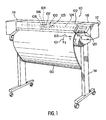
- a printer 110 includes a housing 112 mounted on a stand 114.
- the housing has left and right drive mechanism enclosures 116 and 118.
- a control panel 120 is mounted on the right enclosure 118.
- a carriage assembly 100 illustrated in phantom under a cover 122, is adapted for reciprocal motion along a carriage bar 124, also shown in phantom.
- the carriage assembly 100 comprises four inkjet printheads 102, 104, 106, 108 that store ink of different colours, e.g. black, magenta, cyan and yellow ink respectively, and an optical sensor 105.
- the position of the carriage assembly 100 in a horizontal or carriage scan axis (Y) is determined by a carriage positioning mechanism with respect to an encoder strip. (not shown).
- a print medium 130 such as paper is positioned along a vertical or media axis by a media axis mechanism (not shown).
- the media axis is called the X axis denoted as 101
- the scan axis is called the Y axis denoted as 103.
- an holddown system is globally referenced as 200.
- Such a holddown system 200 is located between the left and right drive mechanism enclosures 116 and 118.
- the width of the holddown system along the Y axis is at least equal to the maximum allowable width of the media. In this example it should allow the employment of medium having width up to 36'', i.e. 914 mm.
- the inkjet printheads 102, 104, 106, 108 are held rigidly in the movable carriage 100 so that the printhead nozzles are above the surface of a portion of the medium 130 which lays substantially flat on a flat stationary support platen 400 of said holddown system 200.
- the flat platen 400 is shown in more details, and is located in a front position of the printer 110 and co-operate with a main driving roller 300, in the following identified also as the main roller, located in a rear position, and a plurality of pinch wheels 310, in this example 12 pinch wheels 310 are employed, which are controlled to periodically index or convey the medium across the surface of the platen 400.
- the force between each pinch wheels 310 and the main roller 300 is comprised between 3.33 N and 5 N, preferably 4.15 N.
- the main roller 300 is provided with a conventional surface having a plurality of circumferencial recesses 305 housing a corresponding plurality of protrusions 405 of the platen 400 extending towards the rear of the printer 110.
- This combination of features allows the medium 130 to reliably move from the main roller 300 to the platen 400 and vice versa.
- the gap between the roller 300 and the platen 400 may allow an edge of the medium to engage the back of the platen itself causing a paper jam.
- the printer 110 comprises, a vacuum source, in this case a fan not shown in the drawings, connected to the atmosphere through a plurality of holes, or apertures, 330, 350 and a vacuum channel 380; such vacuum source generates an air flow by sucking air from the atmosphere.
- a vacuum source in this case a fan not shown in the drawings, connected to the atmosphere through a plurality of holes, or apertures, 330, 350 and a vacuum channel 380; such vacuum source generates an air flow by sucking air from the atmosphere.
- the holes 330, 350 are distributed at a certain distance from the main roller.
- a plurality of first holes 330 lays in a line at a distance comprised between 10 mm and 30 mm, preferably 19 mm and a plurality of secondary holes 350, distributed preferably in line.
- the platen 400 is provided, according to this preferred example, with a plurality of substantially linear grooves having one end closer to and the opposed end further from the main roller 300. Such grooves are linked together to form a continuos slot 320, which crosses substantially the whole width of the platen 400, where such a continuous slot 320 is arranged to have a waved shape.
- the plurality of first holes, or slot holes 330, having a diameter comprises between 1.5 mm and 3.5 mm, preferably about 2.5 mm, are then distributed inside the waved slot 320, and in this embodiment are preferably located in the further part of the slot 320 with respect to the main roller 300.
- the vacuum can be only directly generated at a certain distance from the main roller 300 itself.
- the vacuum source when the vacuum source is activated and in presence of a medium on the platen 400, the vacuum can be expanded along all the slot extending the vacuum closer to the main roller 300.
- extending the vacuum means that the vacuum generated at one aperture, which is normally supplied to an area of the back of medium, is now supplied to an area of the back of the medium which is at least 10% bigger, preferably bigger than 500%.
- Size of the vacuum channel is a further parameter relevant to apply the proper vacuum to the back of the medium.
- the surface of squared section of the vacuum channel 380 is preferably bigger than the sum of the surface of all the apertures 330, 350 distributed within the platen 400. More preferably the surface of the squared section is as big as twice, or more, the sum of the surface of all the apertures 330, 340.
- the medium can still be indexed by the main roller 300 and the pinch rollers 310 even when we are printing close to the very end of the medium itself.
- high vacuum may crease the paper especially if the grooves of the slot 320 are wide and run parallel to the paper advance direction. Therefore is advisable to run the grooves at about 45° respect to the media axis X and optimise the slot width to minimise creases in the paper and to evenly distribute the vacuum.
- the groove if the groove is parallel to the advance direction, it may make the ink to migrate and create localised dark areas.
- the slot 320 has a depth deeper than 0.5 mm, preferably 1 mm, and a width comprises between 3 mm and 8 mm, preferably 5 mm.
- the continuous shape of the waved slot 320 helps the holddown system 200 to evenly distribute the vacuum along the print zone 450.
- an interrupted sequence of grooves may create areas, having a reduced vacuum, which cross the complete print zone 450, in the media axis direction X. This may force the ink applied in those areas to migrate and create localised dark or clear portions in the printout.
- each recess 360 is composed by two parts, a first one substantially squared and a second one substantially triangular, where the triangular part lays on a plane which deeper than the plane on which the squared part lays.
- each squared part is provided with a secondary hole 350, having a diameter comprises between 1.5 and 2.5 mm, preferably 2.0.
- Such sequence of secondary recesses 360 is combined with a sequence of overdrive wheels 340, forming a secondary roller 345, such that a group of 3 consecutive secondary recesses 360 is disposed between two consecutive wheels 340.
- Such a secondary roller is housed in the vacuum channel 380.
- this holddown system 200 comprises 12 overdrive wheels 340 equally separated along the scan axis (Y) to supply equal traction to each part of the medium.
- an overdrive wheel may mean a single wheel as well as a plurality of wheels in strict contact one to another, in order to build a wheel having a larger width.
- a secondary recess 360 is distanced by each adjacent element, both a further secondary recess 360 or a wheel 340, by a rib 370.
- the ribs are employed to reduce the risk of generating cockle wrinkles which may extend towards the print zone 450.
- two consecutive ribs 370 having a preferably height of 1 mm, are distanced one to another by a distance comprised between 15 mm and 25 mm, preferably about 20 mm if the two ribs 370 are separated by a secondary recess 360.
- the plurality of secondary holes 350 provides the vacuum channel 380 with further apertures for the air flow generated by the vacuum source.
- the particular shape of the recesses 360 helps to provide the air flow with a smooth transition, reducing the resulting noise.
- the vacuum generated in correspondence of the secondary holes 350 is extended, in order to apply a negative pressure to most of the medium 130 laying on the platen 400.
- the vacuum is extended particularly due to the presence of the overdrive wheels 340, and the ribs 370, which create a larger empty space between the medium 130 and the platen 400.
- this part of the holddown system helps the printer to reduce the cockle effect on the printout.
- a secondary roller 345 having the function of tensioning the paper during the printing operation, may help in controlling the occurrence of the cockle wrinkles in the printout.
- vacuum is furnished through the plurality of holes 350 and the gap between each overdrive wheel 340 and its surrounding portion of the platen 400.
- Vacuum is used to provide the force between medium and overdrive wheels 340; the design has been done in such a way that it can provide the required force to the overdrive wheel 340, preferably comprised between 0.6 N and 1 N, in this example 0.8 N per each wheel 340, without employing starwheels. Elimination of starwheels is an important issue since it helps to avoid a) the risk of damaging the printout with starwheel marks, b)the need to employ a mechanism or a structure to hold the starwheels themselves.
- the overdrive interference i.e. the distance between the surface of the platen 400 and the top of the a overdrive roller 340, is preferably maintained between 0.3 mm and 0.6 mm. Below 0.25 mm the traction falls quickly, towards zero traction at zero interference; if the interference is bigger than 0.65 mm, wrinkles created by the overdrive roller 340 can extend to the print zone 450.
- first reference sign 390 is traversing all the platen 400 from the right to the left side in the scan axis (Y) direction.
- first reference 390 is tangent to the slot 320, on the side closer to the main roller 300, and it could be in colour and/or in under-relief.
- This feature is used preferably in combination with a second reference 392, placed at one side end of the platen 400.
- the second reference is traversing the platen 400 in the media axis (X) direction, preferably starting from the first reference 390 to the end of the platen 400 further from the main roller 300.
- the user is provided with two references for placing correctly the edges of a cut media sheet, or a media roll, onto the platen 400 in order to load and feed the sheet into the printer 110.
- the first reference 390 is providing the user with a reference which can fully match an edge of the sheet, so simplifying the loading operation.
- a second reference is placed at one end of the platen 400, which is conventionally located at the right end of the printer, respect to the user placing the sheet.
- This combination of references enhances the easiness of the loading operation by the user, reducing the occurrence of inaccurate positioning of the medium, which may cause a paper jam, during the feeding or the printing phases.
- FIG 4 it is shown the main roller 300 and one of the pinch wheels 310 co-operating with one protrusion 405 of the platen 400 holding the medium 130.
- One of the overdrive wheels 340, tensioning the medium 130 in the print zone 450 is also shown. From Figure 4 it is better depicted that the vacuum channel 380 does not extend underneath the complete print zone 450, particularly the vacuum channel 380 is partially overlapped by a portion of the print zone 450 which is less than 90% of the complete print zone 450, preferably less than 50%, and more preferably about 30-35%.
- FIG. 5 a diagram showing nominal values supplied by the vacuum source, a fan, employed in this example. Those values have been measured running the fan at its full power of 24 V.
- the pressure unit on the Y axis is Pascal and air flow unit on the X axis is m 3 /min.
- Vacuum required to eliminate cockle wrinkles in a printer would be so high that is normally unfeasible; in fact, high vacuum may suck the ink right through the paper and at the same time generate a lot of noise.
- the vacuum level has been preferably set between 380 Pa and 440 Pa, which can be achieved by a small fan, producing acceptable level of noise, i.e. about 65 dBA.
- one characteristic of the fan considered particularly valuable has been the capability of providing a pressure of 300 Pa, when the air flow is at about 0.5 m 3 /min.
- a loading operation can be activated in a plurality of different ways, e.g. by a user selection of the operation from the front panel 120 of the printer 110, or more easily, as in this embodiment, by opening the cover 122.
- the vacuum source is powered on, at 16 V, in order to help the loading operation.
- a user In order to load a cut sheet of media into the printer, a user should place the top edge of the medium 130 in correspondence of the first reference 390, and the top portion of the right edge of the same medium 130 in correspondence of the second reference. During all this phase the vacuum on is helping the user in holding the medium 130 adherent to the platen 400, so that small adjustments in the position of the medium 130 can be done using only one hand. Accordingly, the risk of inadvertently damaging the medium 130 (e.g. due to fingerprints or to the fall of the medium 130 on the ground) are minimised.
- the feeding step may be activated in several ways. For instance, it is automatically activated after that sensors have sensed the proper positioning of the medium 130, or by user selection of the feeding operation from the front panel 118, or, as in this embodiment, by closing the cover 122.
- the overdrive wheels 340 start to move clockwise in order to advance the medium 130 towards the main roller 300, until the medium 130 itself is engaged between the main roller and the pinch wheels 310.
- the vacuum is maintained on to transmit the traction force from the overdrive wheels 340 to the medium 130.
- the main roller 300 in co-operation with the pinch rollers 310 and other conventional elements of the printer 110, starts to convey the medium, from the feeding guide, across the print zone defined onto the platen 400.
- the vacuum source is switched on, at a power according to the kind of media employed and/or to the kind of plot which will be printed.
- the vacuum is keeping the medium 130 substantially flat onto the print zone 450 defined on the platen 400 to allow a quality printing.
- the main roller is advancing the medium towards the overdrive wheels 340, to have the medium engaged by them.
- the medium should be tensioned in the media direction X to keep the cockle wrinkles under control.
- the printing may start even if the overdrive wheels 340 are not engaged yet with the medium.
- the advance of the medium in the print zone along the media axis direction X is performed by a pushing force provided by the main roller 300, moving counter-clockwise, and the pinch wheels 310, moving clockwise, and by a pulling force provided by the overdrive wheels 340, moving counter-clockwise too.
- Conventional printing steps allow the carriage assembly 100 to move the printheads 102, 104, 106, and 108, relative to the medium 130 along the scan axis Y, in order to apply ink to the medium 130, in one or more passes, and so reproducing the desired image.
- An outputting operation may be activated for instance a) automatically when a printing operation has been completed or aborted, or b ) manually by a user request.
- the printer verifies if the medium 130 to be outputted is a cut sheet or a roll. If the medium 130 is a roll a cutting step is performed. This means that the medium 130 is advanced in the cutting position and the vacuum source is powered on, at 22 V, to hold the medium substantially flat and minimise the movement of the same while a blade, not show, is traversing the medium 130 along the scan axis Y to cut the medium.
- the medium 130 is a cut sheet or after that the roll has been cut, the medium is advanced in the media axis direction X towards the front of the printer 110, i.e. further from the main roller 300.
- the advancement of the medium is performed by the counter-clockwise movement of the overdrive wheels 340, frictionally engaging a portion of the back of the medium 130, due to the negative pressure generated by the vacuum source applied to the medium 130. If a cut sheet of media 130 is still engaged with the main roller 300 and the pinch wheels 310, those elements are also co-operating to advance the medium.
- the overdrive wheels movement is stopped when most of the printout is advanced out of the printer, e.g. as shown in Figure 1.
- the vacuum source is kept on for the required time to dry the medium, so holding only an end region of the medium 130, preferably having length equal to the width of the medium 130 and about 50 mm in the media axis direction X.
- the vacuum is switched off to drop the medium 130, e.g. into a conventional collecting bin, not shown.
- the same holddown system e.g. having one platen and one vacuum source
- the same holddown system may be capable of being employed to perform a plurality different operations, such as loading and feeding operation, printing operation and outputting operation.
- each of this operations may be performed also using independent holddown systems, i.e. independent holddown surfaces and/or independent vacuum source.
- independent holddown systems i.e. independent holddown surfaces and/or independent vacuum source.
- the skilled in the art is now aware that only some of those operations may be performed by means of a vacuum holddown system while the remaining ones may be performed employing conventional systems.
Landscapes
- Handling Of Sheets (AREA)
- Ink Jet (AREA)
- Handling Of Cut Paper (AREA)
Priority Applications (8)
| Application Number | Priority Date | Filing Date | Title |
|---|---|---|---|
| EP98120706A EP0997302B1 (fr) | 1998-10-30 | 1998-10-30 | Appareil d'enregistrement d'images et procédé pour maintenir en position basse des supports d'enregistrement |
| DE69828880T DE69828880T2 (de) | 1998-10-30 | 1998-10-30 | Bilderzeugungsgerät und Verfahren zum Niederhalten von Aufzeichnungsträgermaterial |
| ES98120706T ES2232907T3 (es) | 1998-10-30 | 1998-10-30 | Aparato de copiado y metodo para la retencion de soportes de copiado. |
| EP19990102977 EP0997308B1 (fr) | 1998-10-30 | 1999-02-15 | Dispositif d'impression et procédé pour produire une pression uniforme pour maintenir des medias en bas |
| DE69940377T DE69940377D1 (de) | 1998-10-30 | 1999-02-15 | Druckgerät und Verfahren zur Erzeugung eines gleichmässigen Druckes zum Niederhalten von Druckmedien |
| JP11308116A JP2000135825A (ja) | 1998-10-30 | 1999-10-29 | 媒体を抑制するハ―ドコピ―装置および方法 |
| JP11309265A JP2000135828A (ja) | 1998-10-30 | 1999-10-29 | 媒体押さえ可能なハ―ドコピ―装置 |
| US10/096,242 US6554415B2 (en) | 1998-10-30 | 2002-03-12 | Hardcopy apparatus and method for holding down media |
Applications Claiming Priority (1)
| Application Number | Priority Date | Filing Date | Title |
|---|---|---|---|
| EP98120706A EP0997302B1 (fr) | 1998-10-30 | 1998-10-30 | Appareil d'enregistrement d'images et procédé pour maintenir en position basse des supports d'enregistrement |
Publications (2)
| Publication Number | Publication Date |
|---|---|
| EP0997302A1 true EP0997302A1 (fr) | 2000-05-03 |
| EP0997302B1 EP0997302B1 (fr) | 2005-02-02 |
Family
ID=8232904
Family Applications (1)
| Application Number | Title | Priority Date | Filing Date |
|---|---|---|---|
| EP98120706A Expired - Lifetime EP0997302B1 (fr) | 1998-10-30 | 1998-10-30 | Appareil d'enregistrement d'images et procédé pour maintenir en position basse des supports d'enregistrement |
Country Status (5)
| Country | Link |
|---|---|
| US (1) | US6554415B2 (fr) |
| EP (1) | EP0997302B1 (fr) |
| JP (1) | JP2000135825A (fr) |
| DE (2) | DE69828880T2 (fr) |
| ES (1) | ES2232907T3 (fr) |
Cited By (6)
| Publication number | Priority date | Publication date | Assignee | Title |
|---|---|---|---|---|
| EP1182041A1 (fr) * | 2000-08-24 | 2002-02-27 | Hewlett-Packard Company, A Delaware Corporation | Imprimante à jet d'encre |
| EP1308303A1 (fr) | 2001-10-31 | 2003-05-07 | Hewlett Packard Company, a Delaware Corporation | Adaptateur faisant le vide sur une zone d'impression utilisé pour un dispositif d'impression |
| EP1454758A1 (fr) * | 2003-03-07 | 2004-09-08 | Seiko Epson Corporation | Dispositif de transport de medium et appareil d'enregistrement |
| CN103240988A (zh) * | 2012-02-09 | 2013-08-14 | 精工爱普生株式会社 | 液体喷射装置 |
| US20140085390A1 (en) * | 2012-09-27 | 2014-03-27 | Timothy J. Young | Vacuum pulldown of web in printing systems |
| US9205675B2 (en) | 2010-11-11 | 2015-12-08 | OCé PRINTING SYSTEMS GMBH | Device for drying a recording medium which is printed with ink in a printer, and method therefor |
Families Citing this family (6)
| Publication number | Priority date | Publication date | Assignee | Title |
|---|---|---|---|---|
| US7016059B1 (en) * | 1999-08-31 | 2006-03-21 | Shutterfly, Inc. | Printing images in an optimized manner |
| JP3666491B2 (ja) * | 2002-03-29 | 2005-06-29 | セイコーエプソン株式会社 | インクカートリッジ及び記録装置 |
| US7309179B2 (en) * | 2005-04-29 | 2007-12-18 | Hewlett-Packard Development Company, L.P. | Media advancing device and method of displacing a medium |
| BRPI0802964A2 (pt) * | 2008-07-09 | 2009-05-19 | Riskema Informatica E Automacaoltda | plotter vertical jato de tinta |
| JP2018176497A (ja) * | 2017-04-07 | 2018-11-15 | セイコーエプソン株式会社 | 液体吐出装置 |
| JP7148854B2 (ja) * | 2018-02-15 | 2022-10-06 | セイコーエプソン株式会社 | 媒体給送装置、画像読取装置 |
Citations (3)
| Publication number | Priority date | Publication date | Assignee | Title |
|---|---|---|---|---|
| JPS61237667A (ja) * | 1985-04-15 | 1986-10-22 | Tokyo Electric Co Ltd | 印刷装置 |
| EP0409596A2 (fr) * | 1989-07-19 | 1991-01-23 | Seiko Instruments Inc. | Appareil d'enregistrement à jet d'encre |
| JPH0577997A (ja) * | 1991-09-18 | 1993-03-30 | Brother Ind Ltd | 印字装置 |
Family Cites Families (3)
| Publication number | Priority date | Publication date | Assignee | Title |
|---|---|---|---|---|
| JPH0262275A (ja) * | 1988-08-30 | 1990-03-02 | Brother Ind Ltd | 記録装置 |
| CA2049571C (fr) * | 1990-10-19 | 2004-01-13 | Kent D. Vincent | Imprimante thermique a jet d'encre haute definition |
| JPH1035186A (ja) * | 1996-07-19 | 1998-02-10 | Mutoh Ind Ltd | 自動製図機 |
-
1998
- 1998-10-30 DE DE69828880T patent/DE69828880T2/de not_active Expired - Lifetime
- 1998-10-30 ES ES98120706T patent/ES2232907T3/es not_active Expired - Lifetime
- 1998-10-30 EP EP98120706A patent/EP0997302B1/fr not_active Expired - Lifetime
-
1999
- 1999-02-15 DE DE69940377T patent/DE69940377D1/de not_active Expired - Lifetime
- 1999-10-29 JP JP11308116A patent/JP2000135825A/ja not_active Withdrawn
-
2002
- 2002-03-12 US US10/096,242 patent/US6554415B2/en not_active Expired - Lifetime
Patent Citations (3)
| Publication number | Priority date | Publication date | Assignee | Title |
|---|---|---|---|---|
| JPS61237667A (ja) * | 1985-04-15 | 1986-10-22 | Tokyo Electric Co Ltd | 印刷装置 |
| EP0409596A2 (fr) * | 1989-07-19 | 1991-01-23 | Seiko Instruments Inc. | Appareil d'enregistrement à jet d'encre |
| JPH0577997A (ja) * | 1991-09-18 | 1993-03-30 | Brother Ind Ltd | 印字装置 |
Non-Patent Citations (2)
| Title |
|---|
| PATENT ABSTRACTS OF JAPAN vol. 011, no. 082 (M - 571) 12 March 1987 (1987-03-12) * |
| PATENT ABSTRACTS OF JAPAN vol. 017, no. 403 (M - 1453) 28 July 1993 (1993-07-28) * |
Cited By (9)
| Publication number | Priority date | Publication date | Assignee | Title |
|---|---|---|---|---|
| EP1182041A1 (fr) * | 2000-08-24 | 2002-02-27 | Hewlett-Packard Company, A Delaware Corporation | Imprimante à jet d'encre |
| US6517179B2 (en) | 2000-08-24 | 2003-02-11 | Hewlett-Packard Company | Inkjet printing apparatus |
| EP1308303A1 (fr) | 2001-10-31 | 2003-05-07 | Hewlett Packard Company, a Delaware Corporation | Adaptateur faisant le vide sur une zone d'impression utilisé pour un dispositif d'impression |
| EP1454758A1 (fr) * | 2003-03-07 | 2004-09-08 | Seiko Epson Corporation | Dispositif de transport de medium et appareil d'enregistrement |
| US7390085B2 (en) | 2003-03-07 | 2008-06-24 | Seiko Epson Corporation | Medium transporting device and recording apparatus |
| USRE44041E1 (en) | 2003-03-07 | 2013-03-05 | Seiko Epson Corporation | Medium transporting device and recording apparatus |
| US9205675B2 (en) | 2010-11-11 | 2015-12-08 | OCé PRINTING SYSTEMS GMBH | Device for drying a recording medium which is printed with ink in a printer, and method therefor |
| CN103240988A (zh) * | 2012-02-09 | 2013-08-14 | 精工爱普生株式会社 | 液体喷射装置 |
| US20140085390A1 (en) * | 2012-09-27 | 2014-03-27 | Timothy J. Young | Vacuum pulldown of web in printing systems |
Also Published As
| Publication number | Publication date |
|---|---|
| DE69828880T2 (de) | 2006-03-30 |
| EP0997302B1 (fr) | 2005-02-02 |
| ES2232907T3 (es) | 2005-06-01 |
| US20020126190A1 (en) | 2002-09-12 |
| JP2000135825A (ja) | 2000-05-16 |
| US6554415B2 (en) | 2003-04-29 |
| DE69940377D1 (de) | 2009-03-19 |
| DE69828880D1 (de) | 2005-03-10 |
Similar Documents
| Publication | Publication Date | Title |
|---|---|---|
| EP0997306B1 (fr) | Dispositif de copie sur papier et méthode de sortie des supports d'information | |
| EP0997302B1 (fr) | Appareil d'enregistrement d'images et procédé pour maintenir en position basse des supports d'enregistrement | |
| US7744210B2 (en) | Moving floor media transport for digital printers | |
| US5729817A (en) | Accent printer for continuous web material | |
| US20070165092A1 (en) | Ink jet recording apparatus | |
| US8348415B2 (en) | Recording paper transportation path structure and printer | |
| US6682190B2 (en) | Controlling media curl in print-zone | |
| US6786664B2 (en) | Active vacuum roller and method for advancing media | |
| JP2007145485A (ja) | 記録媒体搬送機構及びこれを備えた画像記録装置 | |
| WO2006120166A1 (fr) | Aide au maintien du support pour le transport progressif dudit support dans une imprimante numerique | |
| US6367999B1 (en) | Hardcopy apparatus and method for providing uniform pressure to hold down media | |
| EP1022147B1 (fr) | Système de transport de médias | |
| US6386536B1 (en) | Hardcopy apparatus and method for loading media | |
| EP3251989B1 (fr) | Enroulement de bande à serrage par friction | |
| EP0997308B1 (fr) | Dispositif d'impression et procédé pour produire une pression uniforme pour maintenir des medias en bas | |
| JP4192083B2 (ja) | プリンタ | |
| JP3935310B2 (ja) | プリンタの媒体形状制御用内部紙案内 | |
| JP4265593B2 (ja) | インクジェット記録装置 | |
| JP2001268310A (ja) | 画像形成装置及びロール状記録媒体切断方法 | |
| US8561988B1 (en) | Media hold-down for printing system | |
| CN112078245A (zh) | 装载装置、打印机 | |
| JP2001071480A (ja) | プリンタ装置 | |
| JPH02286546A (ja) | 給排紙トレイ | |
| JP2001058738A (ja) | 印字用紙搬送機構 | |
| JP2003326781A (ja) | インクジェット記録装置 |
Legal Events
| Date | Code | Title | Description |
|---|---|---|---|
| PUAI | Public reference made under article 153(3) epc to a published international application that has entered the european phase |
Free format text: ORIGINAL CODE: 0009012 |
|
| AK | Designated contracting states |
Kind code of ref document: A1 Designated state(s): DE ES FR GB NL |
|
| AX | Request for extension of the european patent |
Free format text: AL;LT;LV;MK;RO;SI |
|
| 17P | Request for examination filed |
Effective date: 20001030 |
|
| AKX | Designation fees paid |
Free format text: DE ES FR GB NL |
|
| RAP1 | Party data changed (applicant data changed or rights of an application transferred) |
Owner name: HEWLETT-PACKARD COMPANY, A DELAWARE CORPORATION |
|
| 17Q | First examination report despatched |
Effective date: 20030710 |
|
| GRAP | Despatch of communication of intention to grant a patent |
Free format text: ORIGINAL CODE: EPIDOSNIGR1 |
|
| GRAS | Grant fee paid |
Free format text: ORIGINAL CODE: EPIDOSNIGR3 |
|
| GRAA | (expected) grant |
Free format text: ORIGINAL CODE: 0009210 |
|
| AK | Designated contracting states |
Kind code of ref document: B1 Designated state(s): DE ES FR GB NL |
|
| REG | Reference to a national code |
Ref country code: GB Ref legal event code: FG4D |
|
| REF | Corresponds to: |
Ref document number: 69828880 Country of ref document: DE Date of ref document: 20050310 Kind code of ref document: P |
|
| REG | Reference to a national code |
Ref country code: ES Ref legal event code: FG2A Ref document number: 2232907 Country of ref document: ES Kind code of ref document: T3 |
|
| PLBE | No opposition filed within time limit |
Free format text: ORIGINAL CODE: 0009261 |
|
| STAA | Information on the status of an ep patent application or granted ep patent |
Free format text: STATUS: NO OPPOSITION FILED WITHIN TIME LIMIT |
|
| ET | Fr: translation filed | ||
| 26N | No opposition filed |
Effective date: 20051103 |
|
| PGFP | Annual fee paid to national office [announced via postgrant information from national office to epo] |
Ref country code: NL Payment date: 20071024 Year of fee payment: 10 Ref country code: ES Payment date: 20071026 Year of fee payment: 10 |
|
| PGFP | Annual fee paid to national office [announced via postgrant information from national office to epo] |
Ref country code: FR Payment date: 20071017 Year of fee payment: 10 |
|
| NLV4 | Nl: lapsed or anulled due to non-payment of the annual fee |
Effective date: 20090501 |
|
| REG | Reference to a national code |
Ref country code: FR Ref legal event code: ST Effective date: 20090630 |
|
| PG25 | Lapsed in a contracting state [announced via postgrant information from national office to epo] |
Ref country code: NL Free format text: LAPSE BECAUSE OF NON-PAYMENT OF DUE FEES Effective date: 20090501 |
|
| PG25 | Lapsed in a contracting state [announced via postgrant information from national office to epo] |
Ref country code: FR Free format text: LAPSE BECAUSE OF NON-PAYMENT OF DUE FEES Effective date: 20081031 |
|
| REG | Reference to a national code |
Ref country code: ES Ref legal event code: FD2A Effective date: 20081031 |
|
| PG25 | Lapsed in a contracting state [announced via postgrant information from national office to epo] |
Ref country code: ES Free format text: LAPSE BECAUSE OF NON-PAYMENT OF DUE FEES Effective date: 20081031 |
|
| REG | Reference to a national code |
Ref country code: GB Ref legal event code: 732E Free format text: REGISTERED BETWEEN 20120329 AND 20120404 |
|
| PGFP | Annual fee paid to national office [announced via postgrant information from national office to epo] |
Ref country code: GB Payment date: 20160928 Year of fee payment: 19 |
|
| PGFP | Annual fee paid to national office [announced via postgrant information from national office to epo] |
Ref country code: DE Payment date: 20160922 Year of fee payment: 19 |
|
| REG | Reference to a national code |
Ref country code: DE Ref legal event code: R119 Ref document number: 69828880 Country of ref document: DE |
|
| GBPC | Gb: european patent ceased through non-payment of renewal fee |
Effective date: 20171030 |
|
| PG25 | Lapsed in a contracting state [announced via postgrant information from national office to epo] |
Ref country code: DE Free format text: LAPSE BECAUSE OF NON-PAYMENT OF DUE FEES Effective date: 20180501 Ref country code: GB Free format text: LAPSE BECAUSE OF NON-PAYMENT OF DUE FEES Effective date: 20171030 |