EP0997239A2 - Rohr und/oder Kabelanordnung in einem Roboter mit Parallelstangen - Google Patents
Rohr und/oder Kabelanordnung in einem Roboter mit Parallelstangen Download PDFInfo
- Publication number
- EP0997239A2 EP0997239A2 EP99308501A EP99308501A EP0997239A2 EP 0997239 A2 EP0997239 A2 EP 0997239A2 EP 99308501 A EP99308501 A EP 99308501A EP 99308501 A EP99308501 A EP 99308501A EP 0997239 A2 EP0997239 A2 EP 0997239A2
- Authority
- EP
- European Patent Office
- Prior art keywords
- cables
- cable
- link mechanism
- pipes
- parallel link
- Prior art date
- Legal status (The legal status is an assumption and is not a legal conclusion. Google has not performed a legal analysis and makes no representation as to the accuracy of the status listed.)
- Withdrawn
Links
Images
Classifications
-
- B—PERFORMING OPERATIONS; TRANSPORTING
- B25—HAND TOOLS; PORTABLE POWER-DRIVEN TOOLS; MANIPULATORS
- B25J—MANIPULATORS; CHAMBERS PROVIDED WITH MANIPULATION DEVICES
- B25J17/00—Joints
- B25J17/02—Wrist joints
- B25J17/0208—Compliance devices
- B25J17/0216—Compliance devices comprising a stewart mechanism
Definitions
- the present invention relates to a structure of a cable and/or pipe arrangement applied in a parallel link mechanism used by an industrial robot, a burr remover, a machining center, a drill or the like effecting boring, or a YAG laser machine or the like effecting boring, welding or the like on a thin plate. These are merely examples of use.
- a parallel link mechanism is well known where a fixed plate and a movable plate are connected to each other by a plurality of link members arranged in parallel, and the respective link members are extended/retracted in cooperating manner so that the movable plate is moved relative to the fixed plate.
- the links are arranged side-by-side, in parallel in the same sense that electrical components may be in parallel, as opposed to being in series.
- the links are not necessarily geometrically parallel to one another, and indeed in many cases they are not.
- the parallel link mechanism can cause the movable plate to take any position and attitude relative to the fixed plate and can operate the movable plate with a high accuracy. Also, the respective link members can be arranged close to one another so that the parallel link mechanism can be structured compactly. Though the parallel link mechanism has the above advantages, it has a disadvantage in that there is less space utilized for a cable and/or pipe arrangement to drive control equipment provided for the parallel link mechanism or for a cable and/or pipe arrangement to an end effector mounted on the movable plate.
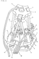
- a parallel link mechanism comprises a fixed plate 1 serving as a supporting plate, a movable plate 2 mounted with such a device as an end effector, a hand, an additional shaft or the like, a plurality (6 in the example in Fig. 4) of stretchable/retractable link members 3 connecting the fixed plate 1 and the movable plate 2 to each other, converting means 5 provided for the respective link members 3 to stretch/retract them, and drive control devices 4 for respectively driving the link members 3 via the converting means 5.
- Each converting means 5 comprises a ball nut (not shown) formed in a sleeve shape at one end of the link member 3 and a ball screw engaged with an inside of the ball nut in a threading manner, and it is a mechanism for converting rotating movement to linear movement.
- Each drive control device 4 for driving the converting means 5 to stretch/retract the link member 3 comprises a servomotor (not shown) and a position/speed detector mounted on the servomotor or the like. The ball screws are individually rotated by the servomotors respectively constituting the drive control devices 4 so that substantial lengths of the respective link members 3 can individually be changed.
- joints 6 for supporting the respective lower end portions of the respective link members 3 are disposed on the fixed plate 1 via the respective converting means 5.
- joints 7 for coupling upper ends of adjacent two link members 3 to each other are disposed one by one at positions of apexes of regular triangles assumed on the movable plate 2.
- Each joint 6 disposed on the fixed plate 1 constitutes an articulate having the degree of freedom of 2 and it allows pivoting movement of each link member 3 relative to the fixed plate 1 in all directions.
- each joint 7 disposed on the movable plate 2 constitutes an articulate having the degree of freedom of 2 or 3 and it allows pivoting movement of the link member 3 relative to the movable plate 2.
- Cables 10 are respectively connected to the servomotors respectively constituting the drive control devices 4 for driving the respective link members 3 and the position/speed detectors respectively mounted on the servomotors. As illustrated in Fig. 4, the cables 10 reach the fixed plate 1 from the outside of the parallel link mechanism and therefrom extend to the servomotors or the position/speed detectors. The cables 10 are respectively fixed by fixtures on members on which the servomotors are respectively mounted.
- Cables 11 are connected to a device (not shown) mounted on the movable plate 2, for example an end effector.
- the cables 11 go around the outside of the parallel link mechanism to the device.
- the link members 3 of the parallel link mechanism are pivoted or swung.
- the drive control devices 4 for respectively driving the link members 3 are also pivoted.
- the cables 10 connected to the servomotors constituting the drive control devices 4 and the position/speed detectors are also moved. There may occur that the cables 10 come in contact with the fixed plate 1 to be rubbed according to their movements and covers thereof are torn so that they are short-circuited or broken.
- the cables 10 are disposed with such plays that they can follow change in position or attitude of the movable plate 2 so as not to contact with the fixed plate 1 even when the cables 10 are moved.
- An object of the present invention is to provide a parallel link mechanism with a cable and/or pipe arrangement so as to avoid cables and/or pipes used in the parallel link mechanism from coming into contact with members constituting the parallel link mechanism to be rubbed, and so as not to prevent peripheral devices from being disposed around the parallel link mechanism.
- An aspect of the present invention is a structure of a cable and/or pipe arrangement for a parallel link mechanism where a fixed member and a movable member are provided, both of them are connected to each other by a plurality of link members arranged in parallel, and the movable member is moved relative to the fixed plate by driving the respective link members, wherein a plurality of cables and/or pipes led to the fixed member from the outside of the parallel link mechanism are respectively bent so as to be spaced from the fixed member, the respective cables and/or pipes are clamped by cable/pipe clamping means provide on the fixed member so as to maintain the cables and/or pipes in their bent states, and the respective cables and/or pipes are connected to drive control devices for performing stretching/retracting operations of the respective link members from the clamped positions of the cables and/or pipes.
- Another aspect of the invention is a structure of a cable and/or pipe arrangement for a parallel link mechanism where a fixed member and a movable member are provided, both of them are connected to each other by a plurality of link members arranged in parallel, and the movable member is moved relative to the fixed plate by driving the respective link members, wherein a through hole is formed in the movable member, a cable and/or a pipe connected to a device mounted on the movable member is caused to pass through the through hole, and the cable and/or a pipe is drawn in a space between the fixed member and the movable member.
- the cables and/or pipes connected to the drive control devices for driving the parallel link mechanism are disposed with plays in a space between the movable member and the fixed member. Accordingly, the cables and/or pipes are prevented from coming into contact with another member to be rubbed and injured even when the movable member is operated in a complicated manner. Furthermore, the cables and/or pipes are disposed with a play in the space between the movable member and the fixed member. Therefore, there is not such a drawback that the cables and/or pipes come into contact with another member to be rubbed and injured. In addition, there is not such a drawback that it is necessary to restrain arrangement of peripheral devices and operation of the parallel link mechanism.
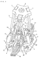
- a cable and/or pipe (which is hereinafter referred simply to as "a cable or cables”) arrangement used in a parallel link mechanism according to a first embodiment will be explained with reference to Fig. 1.
- Fig. 1 Since the parallel link mechanism illustrated in Fig. 1 has the same structure as that of a parallel link mechanism illustrated in Fig. 4, explanation of its structure and operation will be omitted.
- Fig. 1 the same elements as those illustrated in Fig. 4 are denoted by the same reference numerals.
- servomotors constituting six drive control devices 4 are denoted by reference numerals 4a, 4b, 4c, 4d, 4e and 4f.
- the structure of the cable arrangement shown in Fig. 1 is different from the conventional art shown in Fig. 4 in that cable clamping members 20 are fixed on a fixed plate 1 (fixed member) and portions of the cables connected to the respective servomotors 4a to 4f and position/speed detectors mounted on the respective servomotors 4a to 4f are clamped by the cable clamping members 20.
- each clamping member 20 comprises an L-shaped structure having two flat surfaces bent to each other at an angle of about 90°.
- one of the flat faces serves as a mounting surface which is mounted on the fixed plate 1 and the other flat face serves as a cable fixing face on which the cables 10 is fixed.
- two sets of the cable clamping members 20 are used, and the cables 10 are distributed to the respective servomotors 4a to 4f via the two cable clamping members 20.
- some of a plurality of cables 10 grouped in one and extended from a position outside of the parallel link mechanism up to the fixed plate 1 are bent approximately vertically by one of the cable clamping members 20 to advance towards some of the servomotors 4a to 4f and position/speed detectors mounted on the servomotors, while some of the cables 10 are bent approximately vertically by the other cable clamping member 20 to advance towards other some servomotors of the servomotors 4a to 4f and position/speed detectors mounted on the other servomotors.
- each cable 10 bent approximately vertically to the mounting face of the fixed plate 1 by the cable clamping member 20 towards a movable plate 2 (movable member) is clamped on the cable fixing face of the cable clamping member 20.
- each cable 10 extending from its portion clamped by the cable clamping member 20 to its portion connected to one of the servomotors 4a to 4f and the position/speed detectors is given a play or margin to such an extent that shift of the positions of these servomotors 4a to 4f according to change in position and/or attitude of the movable plate 2 is not prevented.
- the section of the cable 10 extending from the portion clamped by the cable clamping member 20 to the portion connected to one of the servomotors 4a to 4f and the position/speed detectors takes a shape where an arc is drawn in a space between the fixed plate 1 and the movable plate 2.
- the sections of the cables 10 extending from their portions clamped by the cable clamping members 20 to the portion connected to the servomotors 4a, 4c, 4d and 4f and the position/speed detectors mounted on the servomotors 4a, 4c, 4d and 4f are fixed at their portions on mounting members of the servomotors through fixtures 12.
- the sections of the cables 10 extending from their portions clamped by the cable clamping members 20 to their portions connected to the servomotors 4b and 4e and the position/speed detectors mounted on the servomotors 4b and 4e need not be fixed at any members including the mounting members of the servomotors.
- the cables 10 respectively have the portions clamped by the cable clamping member 20 to extend vertically to the mounting face of the fixed plate 1 towards the movable member 2 and the portions continuous thereto and drawing an arc in a space, there is no drawback in which they will come into contact with the fixed plate 1 even when the servomotors 4a to 4f are swung or pivoted relative to the fixed plate 1 according to operation of the parallel link mechanism so that they change their attitudes. Accordingly, it can be prevented that the cables 10 come into contact with the parallel link mechanism so that covers of the cables 10 are broken and the cables 10 are short-circuited.
- the cable clamping member 20 serving as the structure of a cable arrangement is constituted by an L-shaped structure having two flat faces bent to each other at an angle of about 90, but another cable clamping member having a different structure from that of the first embodiment is employed in the second embodiment.
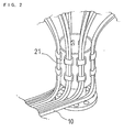
- the second embodiment will be explained with reference to Fig. 2 below.
- a cable clamping member 21 serving as the structure of a cable arrangement shown in Fig. 2 comprises a cylindrical structure formed at its one end with a flange portion.
- the cable clamping member 21 is fixed at an almost central portion of the fixed plate 1 in a state where an end face of the flange portion comes into contact with a face of the fixed plate 1.
- a plurality of cables 10 extending as a group from a position outside the parallel link mechanism on to the fixed plate 1 are clamped on a cylindrical portion peripheral surface (that is, a cable fixing surface) of the cable clamping member 21 to be bent approximately vertically, as shown in Fig. 2.
- the cables 10 bent by cable clamping member 21 further extend upward towards the movable plate 2, (namely, extend approximately along an axial direction of the cylindrical portion of the cable clamping member 21), they each are bent in an arc shape in a space between the fixed plate 1 and the movable plate 2 and thereafter respectively reach the servomotors 4a to 4f and the position/speed detectors.
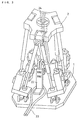
- Cables 23 illustrated in Fig. 3 are connected to such a device (not shown) as an end effector, a hand, an additional shaft or the like.
- a through hole 24 is formed in a central portion of the movable plate 2.
- a cable clamping member 22 is fixed on an approximately central portion of the fixed plate 1.
- the cable clamping member 22 has an L-shaped structure having two flat faces (one is a mounting face which is mounted on the fixed plate 1 and the other is a fixing face which is fixed with the cables 10) bent at an angle of about 90° like the cable clamping member 20 shown in Fig. 1.
- the cable clamping member 22 is formed taller than the cable clamping member 20 shown in Fig. 1.
- a plurality of the cables 23 (two in Fig. 3) extending as a group from a position outside the parallel link mechanism on to the fixed plate 1 are fixed on a cable fixing face of the cable clamping member 22 to be bent approximately vertically and upwardly toward the movable plate 2. Thereafter, the cables pass through the through hole 24 formed in the central portion of the movable plate to be connected to the device mounted on the movable plate 2.
- a section of each cables 23 extending from its portion clamped by the cable clamping member 22 to its portion passing through the through hole 24 of the movable plate 2 is disposed with a play in a space between the fixed plate 1 and the movable plate 2.
- the cables 11 shown in Fig. 4 go around the outside of the parallel link mechanism to reach the device mounted on the movable plate 2. In this embodiment, however, the cables 23 pass through the inside of the parallel link mechanism to reach the device mounted on the movable plate 2. Accordingly, in this embodiment, arrangement of peripheral devices and operation area of the parallel link mechanism is not restricted due to the arrangement of the cables 23.
- first and second groups of cables drawn in from outside of the parallel link mechanism on to the fixed plate are clamped on the cable clamping member to be bent at an angle of about 90° and are extended upwardly towards the movable plate.
- the first group of cables are respectively connected to servomotors for driving the parallel link mechanism, while the second group of cables are caused to pass through a central through hole of the movable plate to be connected to a device mounted on the movable plate.
- the cables are arranged in the above manner, they are prevented from coming into contact with another member, and it becomes unnecessary for the cables to go around an outer periphery of the parallel link mechanism.
Landscapes
- Engineering & Computer Science (AREA)
- Robotics (AREA)
- Mechanical Engineering (AREA)
- Manipulator (AREA)
- Machine Tool Units (AREA)
- Supports For Pipes And Cables (AREA)
Applications Claiming Priority (2)
| Application Number | Priority Date | Filing Date | Title |
|---|---|---|---|
| JP32141898 | 1998-10-27 | ||
| JP10321418A JP2000126954A (ja) | 1998-10-27 | 1998-10-27 | パラレルリンク機構に用いるケーブル、配管の処理構造 |
Publications (2)
| Publication Number | Publication Date |
|---|---|
| EP0997239A2 true EP0997239A2 (de) | 2000-05-03 |
| EP0997239A3 EP0997239A3 (de) | 2000-08-02 |
Family
ID=18132334
Family Applications (1)
| Application Number | Title | Priority Date | Filing Date |
|---|---|---|---|
| EP99308501A Withdrawn EP0997239A3 (de) | 1998-10-27 | 1999-10-27 | Rohr und/oder Kabelanordnung in einem Roboter mit Parallelstangen |
Country Status (2)
| Country | Link |
|---|---|
| EP (1) | EP0997239A3 (de) |
| JP (1) | JP2000126954A (de) |
Cited By (5)
| Publication number | Priority date | Publication date | Assignee | Title |
|---|---|---|---|---|
| WO2005053913A1 (ja) * | 2003-12-03 | 2005-06-16 | Ntn Corporation | リンク作動装置 |
| DE102012025303A1 (de) * | 2012-12-28 | 2014-07-03 | Multivac Sepp Haggenmüller Gmbh & Co. Kg | Schlauchhalter für Roboter |
| US9855621B2 (en) | 2013-11-22 | 2018-01-02 | Ntn Corporation | Automatic welding machine |
| CN109249405A (zh) * | 2018-10-30 | 2019-01-22 | 哈尔滨工业大学(深圳) | 一种移动副驱动的全向大转角高精度姿态调整机器人 |
| CN116207681A (zh) * | 2023-05-05 | 2023-06-02 | 胜利油田固邦泥浆技术服务有限责任公司 | 一种用于定向井的有线侧斜电缆固定防碰装置 |
Families Citing this family (5)
| Publication number | Priority date | Publication date | Assignee | Title |
|---|---|---|---|---|
| JP4862974B2 (ja) * | 2000-10-18 | 2012-01-25 | 第一電気株式会社 | パラレルメカニズム |
| CN102699225B (zh) * | 2012-06-19 | 2013-12-25 | 河北工业大学 | 一种铝边框组件加工的上下料机械手 |
| CN102699221B (zh) * | 2012-06-19 | 2014-04-30 | 河北工业大学 | 一种上下料机械手 |
| JP5682642B2 (ja) * | 2013-03-05 | 2015-03-11 | 株式会社安川電機 | パラレルリンクロボット |
| CN104624837B (zh) * | 2015-02-02 | 2016-03-23 | 佛山市新鹏机器人技术有限公司 | 可实现任意水平转角和垂直方向上下料机器手的传动装置 |
Family Cites Families (5)
| Publication number | Priority date | Publication date | Assignee | Title |
|---|---|---|---|---|
| GB2083795B (en) * | 1980-09-13 | 1984-01-25 | Marconi Co Ltd | Manipulator mechanisms |
| US4739241A (en) * | 1986-10-09 | 1988-04-19 | Georgia Tech Research Corporation | Spherical motor particularly adapted for robotics |
| US4964062A (en) * | 1988-02-16 | 1990-10-16 | Ubhayakar Shivadev K | Robotic arm systems |
| FR2734749B1 (fr) * | 1995-05-29 | 1997-08-14 | Leseure Michel | Manipulateur plan programmable a tres haute cadence et son support universel |
| US5893490A (en) * | 1997-01-27 | 1999-04-13 | Ingersoll-Rand Company | Hose mount for robot arm dispenser system |
-
1998
- 1998-10-27 JP JP10321418A patent/JP2000126954A/ja active Pending
-
1999
- 1999-10-27 EP EP99308501A patent/EP0997239A3/de not_active Withdrawn
Cited By (6)
| Publication number | Priority date | Publication date | Assignee | Title |
|---|---|---|---|---|
| WO2005053913A1 (ja) * | 2003-12-03 | 2005-06-16 | Ntn Corporation | リンク作動装置 |
| EP1690650A4 (de) * | 2003-12-03 | 2008-01-09 | Ntn Toyo Bearing Co Ltd | Verbindungsgliedbetätigungsvorrichtung |
| DE102012025303A1 (de) * | 2012-12-28 | 2014-07-03 | Multivac Sepp Haggenmüller Gmbh & Co. Kg | Schlauchhalter für Roboter |
| US9855621B2 (en) | 2013-11-22 | 2018-01-02 | Ntn Corporation | Automatic welding machine |
| CN109249405A (zh) * | 2018-10-30 | 2019-01-22 | 哈尔滨工业大学(深圳) | 一种移动副驱动的全向大转角高精度姿态调整机器人 |
| CN116207681A (zh) * | 2023-05-05 | 2023-06-02 | 胜利油田固邦泥浆技术服务有限责任公司 | 一种用于定向井的有线侧斜电缆固定防碰装置 |
Also Published As
| Publication number | Publication date |
|---|---|
| EP0997239A3 (de) | 2000-08-02 |
| JP2000126954A (ja) | 2000-05-09 |
Similar Documents
| Publication | Publication Date | Title |
|---|---|---|
| US4904148A (en) | Robot arm for an industrial robot | |
| US8047093B2 (en) | Parallel robot | |
| KR0133995B1 (ko) | 가변 원격탄성중심기기(vrcc) | |
| EP0279591B1 (de) | Handhabungsroboter | |
| US7337691B2 (en) | Parallel kinematics mechanism with a concentric spherical joint | |
| US5611248A (en) | Two-axis robot | |
| KR102206699B1 (ko) | 산업용 로봇 | |
| EP0997239A2 (de) | Rohr und/oder Kabelanordnung in einem Roboter mit Parallelstangen | |
| US20050166699A1 (en) | Horizontal multiple articulation type robot | |
| JP2010184328A (ja) | 3自由度を有する姿勢変更機構を備えたパラレルリンクロボット | |
| JP2004216535A (ja) | 多関節ロボット | |
| US11660764B2 (en) | Robot joint device | |
| JP6765221B2 (ja) | パラレルリンク機構を用いた作業装置 | |
| JP2007015053A (ja) | 産業用ロボット | |
| KR20200016029A (ko) | 다관절 로봇의 케이블 가이드 장치 | |
| US20050072261A1 (en) | Distribution equipment for robot | |
| WO2019049994A1 (ja) | 作業装置 | |
| US20040013509A1 (en) | Parallel kinematics mechanism with a concentric spherical joint | |
| JP2001150382A (ja) | 配線部材及び又は配管部材の案内装置、及び該装置を備えるロボット | |
| EP0997238B1 (de) | Parallelstangenmechanismus | |
| KR102133109B1 (ko) | 확장된 작업영역을 갖는 병렬로봇 | |
| JP2018069354A (ja) | リンク式多関節ロボット | |
| JPH11170184A (ja) | ロボットのアーム構造 | |
| US20230286178A1 (en) | Work device | |
| CN119116010A (zh) | 一种用于深窄环境作业的蛇形机器人 |
Legal Events
| Date | Code | Title | Description |
|---|---|---|---|
| PUAI | Public reference made under article 153(3) epc to a published international application that has entered the european phase |
Free format text: ORIGINAL CODE: 0009012 |
|
| AK | Designated contracting states |
Kind code of ref document: A2 Designated state(s): AT BE CH CY DE DK ES FI FR GB GR IE IT LI LU MC NL PT SE |
|
| AX | Request for extension of the european patent |
Free format text: AL;LT;LV;MK;RO;SI |
|
| PUAL | Search report despatched |
Free format text: ORIGINAL CODE: 0009013 |
|
| AK | Designated contracting states |
Kind code of ref document: A3 Designated state(s): AT BE CH CY DE DK ES FI FR GB GR IE IT LI LU MC NL PT SE |
|
| AX | Request for extension of the european patent |
Free format text: AL;LT;LV;MK;RO;SI |
|
| AKX | Designation fees paid | ||
| REG | Reference to a national code |
Ref country code: DE Ref legal event code: 8566 |
|
| STAA | Information on the status of an ep patent application or granted ep patent |
Free format text: STATUS: THE APPLICATION IS DEEMED TO BE WITHDRAWN |
|
| 18D | Application deemed to be withdrawn |
Effective date: 20010203 |