EP0996519B1 - Laminated metal structure - Google Patents
Laminated metal structure Download PDFInfo
- Publication number
- EP0996519B1 EP0996519B1 EP98936403A EP98936403A EP0996519B1 EP 0996519 B1 EP0996519 B1 EP 0996519B1 EP 98936403 A EP98936403 A EP 98936403A EP 98936403 A EP98936403 A EP 98936403A EP 0996519 B1 EP0996519 B1 EP 0996519B1
- Authority
- EP
- European Patent Office
- Prior art keywords
- metal
- structure according
- metal structure
- foil
- web
- Prior art date
- Legal status (The legal status is an assumption and is not a legal conclusion. Google has not performed a legal analysis and makes no representation as to the accuracy of the status listed.)
- Expired - Lifetime
Links
Images

Classifications
-
- A—HUMAN NECESSITIES
- A61—MEDICAL OR VETERINARY SCIENCE; HYGIENE
- A61M—DEVICES FOR INTRODUCING MEDIA INTO, OR ONTO, THE BODY; DEVICES FOR TRANSDUCING BODY MEDIA OR FOR TAKING MEDIA FROM THE BODY; DEVICES FOR PRODUCING OR ENDING SLEEP OR STUPOR
- A61M39/00—Tubes, tube connectors, tube couplings, valves, access sites or the like, specially adapted for medical use
- A61M39/02—Access sites
- A61M39/0247—Semi-permanent or permanent transcutaneous or percutaneous access sites to the inside of the body
-
- A—HUMAN NECESSITIES
- A61—MEDICAL OR VETERINARY SCIENCE; HYGIENE
- A61L—METHODS OR APPARATUS FOR STERILISING MATERIALS OR OBJECTS IN GENERAL; DISINFECTION, STERILISATION OR DEODORISATION OF AIR; CHEMICAL ASPECTS OF BANDAGES, DRESSINGS, ABSORBENT PADS OR SURGICAL ARTICLES; MATERIALS FOR BANDAGES, DRESSINGS, ABSORBENT PADS OR SURGICAL ARTICLES
- A61L31/00—Materials for other surgical articles, e.g. stents, stent-grafts, shunts, surgical drapes, guide wires, materials for adhesion prevention, occluding devices, surgical gloves, tissue fixation devices
- A61L31/02—Inorganic materials
- A61L31/022—Metals or alloys
-
- B—PERFORMING OPERATIONS; TRANSPORTING
- B22—CASTING; POWDER METALLURGY
- B22F—WORKING METALLIC POWDER; MANUFACTURE OF ARTICLES FROM METALLIC POWDER; MAKING METALLIC POWDER; APPARATUS OR DEVICES SPECIALLY ADAPTED FOR METALLIC POWDER
- B22F7/00—Manufacture of composite layers, workpieces, or articles, comprising metallic powder, by sintering the powder, with or without compacting wherein at least one part is obtained by sintering or compression
- B22F7/002—Manufacture of composite layers, workpieces, or articles, comprising metallic powder, by sintering the powder, with or without compacting wherein at least one part is obtained by sintering or compression of porous nature
- B22F7/004—Manufacture of composite layers, workpieces, or articles, comprising metallic powder, by sintering the powder, with or without compacting wherein at least one part is obtained by sintering or compression of porous nature comprising at least one non-porous part
-
- A—HUMAN NECESSITIES
- A61—MEDICAL OR VETERINARY SCIENCE; HYGIENE
- A61M—DEVICES FOR INTRODUCING MEDIA INTO, OR ONTO, THE BODY; DEVICES FOR TRANSDUCING BODY MEDIA OR FOR TAKING MEDIA FROM THE BODY; DEVICES FOR PRODUCING OR ENDING SLEEP OR STUPOR
- A61M1/00—Suction or pumping devices for medical purposes; Devices for carrying-off, for treatment of, or for carrying-over, body-liquids; Drainage systems
- A61M1/14—Dialysis systems; Artificial kidneys; Blood oxygenators ; Reciprocating systems for treatment of body fluids, e.g. single needle systems for hemofiltration or pheresis
- A61M1/28—Peritoneal dialysis ; Other peritoneal treatment, e.g. oxygenation
- A61M1/285—Catheters therefor
-
- A—HUMAN NECESSITIES
- A61—MEDICAL OR VETERINARY SCIENCE; HYGIENE
- A61M—DEVICES FOR INTRODUCING MEDIA INTO, OR ONTO, THE BODY; DEVICES FOR TRANSDUCING BODY MEDIA OR FOR TAKING MEDIA FROM THE BODY; DEVICES FOR PRODUCING OR ENDING SLEEP OR STUPOR
- A61M39/00—Tubes, tube connectors, tube couplings, valves, access sites or the like, specially adapted for medical use
- A61M39/02—Access sites
- A61M39/0247—Semi-permanent or permanent transcutaneous or percutaneous access sites to the inside of the body
- A61M2039/0261—Means for anchoring port to the body, or ports having a special shape or being made of a specific material to allow easy implantation/integration in the body
-
- A—HUMAN NECESSITIES
- A61—MEDICAL OR VETERINARY SCIENCE; HYGIENE
- A61M—DEVICES FOR INTRODUCING MEDIA INTO, OR ONTO, THE BODY; DEVICES FOR TRANSDUCING BODY MEDIA OR FOR TAKING MEDIA FROM THE BODY; DEVICES FOR PRODUCING OR ENDING SLEEP OR STUPOR
- A61M25/00—Catheters; Hollow probes
- A61M25/01—Introducing, guiding, advancing, emplacing or holding catheters
- A61M25/02—Holding devices, e.g. on the body
- A61M25/04—Holding devices, e.g. on the body in the body, e.g. expansible
-
- B—PERFORMING OPERATIONS; TRANSPORTING
- B22—CASTING; POWDER METALLURGY
- B22F—WORKING METALLIC POWDER; MANUFACTURE OF ARTICLES FROM METALLIC POWDER; MAKING METALLIC POWDER; APPARATUS OR DEVICES SPECIALLY ADAPTED FOR METALLIC POWDER
- B22F2999/00—Aspects linked to processes or compositions used in powder metallurgy
-
- Y—GENERAL TAGGING OF NEW TECHNOLOGICAL DEVELOPMENTS; GENERAL TAGGING OF CROSS-SECTIONAL TECHNOLOGIES SPANNING OVER SEVERAL SECTIONS OF THE IPC; TECHNICAL SUBJECTS COVERED BY FORMER USPC CROSS-REFERENCE ART COLLECTIONS [XRACs] AND DIGESTS
- Y10—TECHNICAL SUBJECTS COVERED BY FORMER USPC
- Y10T—TECHNICAL SUBJECTS COVERED BY FORMER US CLASSIFICATION
- Y10T428/00—Stock material or miscellaneous articles
- Y10T428/12—All metal or with adjacent metals
- Y10T428/12444—Embodying fibers interengaged or between layers [e.g., paper, etc.]
Definitions
- the present invention relates to a laminated sintered metal structure, a method for the manufacture thereof and, more particularly, a medical application therefor.
- metal elements e.g. tubular metal elements, which are porous and yet possess sufficient strength.
- a tubular filter element can be manufactured by combining a metal fibre web, sintered or not, with a metal wire net.
- EP-A-367 354 discloses a subcutaneous part which comprises a mesh sheet of sintered metallic fibers with diameter ranging between 2 and 25 ⁇ m, having a porosity ranging between 70 and 90%, and a holding member comprising a round hole provided with screw tread.
- a laminated or layered metal structure as defined in claim 7.
- Both components of the structure of claim 1 can be made of any metal or metal alloy whatever. Examples are steel, stainless steel or titanium.
- the radially outer component contains metal fibres that can be made by abrading the upper edge of a rolled metal foil, so-called Bekinit® fibres, as described in US-A-4,930,199, or using the bundled drawing technique, as described, e.g., in the patent US-A-3.379,000.
- the metal fibres have an equivalent diameter ranging between 2 ⁇ m and 150 ⁇ m, preferably ranging between 40 ⁇ m and 80 ⁇ m.
- the equivalent diameter of a fibre is the diameter of an imaginary round fibre having the same cross-section as that of the real fibre concerned.
- the metal fibres are then processed to form a contiguous porous fibre layer, for example in the form of a nonwoven web, a knitted, woven or wound fabric or mesh, or in the form of helicoidally and diagonally cross-wound metal fibre filaments.
- the metal structure is a tubular structure and can be provided with longitudinal anchoring or reinforcing ribs along the outer wall, which, among other things, would enhance its mechanical strength.
- Transverse anchoring or reinforcing ribs can also be provided around the outside of the tubular structure.
- Both the longitudinal ribs and the transversal ribs can be of a sintered metal fibre construction, e.g. a sintered steel, stainless steel or titanium fibre construction.
- coated tubular structure according to the present invention can be made of completely bio-inert titanium, thus making the structure exceptionally useful for medical applications. An example of this will be discussed hereunder.
- the metal structure has the form of a frustum of a cone. As will be explained hereinafter, such a form allows to have better sintered bonds between the individual steel fibres or steel filaments.
- the method of manufacturing comprises the following steps :
- the method of manufacturing comprises the following steps :
- a metal structure according to the first aspect of the present invention as a heat exchanger.
- a tubular metal structure 1 according to the first aspect of the present invention has two concentric metal components in the form of a cylinder: a radial inner metal foil 2 and a surrounding component 3 containing metal fibres.
- Stainless steel or titanium may be preferred according to the intended application.
- the metal foil 2 gives the required strength to the tubular metal structure and has a thickness ranging between 20 ⁇ m and 200 ⁇ m.
- the metal foil 2 also renders the coated metal structure 1 impermeable to fluids and adhesives.
- the surrounding component with metal fibres is a sintered metal fibre web 3.
- the sintered metal fibre web has a porosity greater than 80%, e.g. greater than 85% or greater than 90%.
- a method of manufacturing such a laminated tubular structure comprises the following steps :
- Step (a) may be replaced by fitting a pre-formed tubular metal structure such as a tube or a pipe over a core.
- a pre-formed tubular metal structure such as a tube or a pipe
- Step (a) may be replaced by fitting a pre-formed tubular metal structure such as a tube or a pipe over a core.
- the intensity of the sintering treatment in step (d) of the above production method may vary according to the desired strength of the sintered bonds at the points of contact between the metal fibres.
- a supplementary hot isostatic pressing treatment a so called HIP treatment, may be applied, for example at a pressure of about 1000 bar, at a temperature of about 930 °C and in an environment of nearly pure argon gas (99.9999%).
- HIP treatment improves the bonds which have been created between the individual fibres during sintering.
- the metal structure 1 includes a metal foil 2 and a woven layer 4 of continuous metal fibre bundles (marketed under the trade name Bekinit® ).
- the metal structure 1 has 2 layers of continuous fibre filaments 7,8 wound diagonally and sintered on to the metal foil 2.
- Such diagonal winding offers the advantage of a relatively open (porous) structure after sintering.
- tubular metal structure according to the present invention with two or more longitudinal reinforcing or securing ribs 5 along the outer wall, as shown in FIGURE 4.
- the tubular metal structure according to the invention has an inner metal foil and a knitted tubular metal sleeve, as described in the PCT patent application WO 97/04152 by the applicant.
- This structure can be manufactured by slipping the knitted fabric over the tubular metal foil supported by means of a mandrel, clamping the knitted fabric in place, then sintering the structure thus obtained in an oven in a vacuum or using a protective inert gas (e.g. hydrogen gas).
- a protective inert gas e.g. hydrogen gas
- Implant for securing foreign bodies in organic tissue Implant for securing foreign bodies in organic tissue.
- a tubular metal structure according to the first aspect of the present invention can be used as an implant for securing foreign bodies in organic tissue.
- the metal structure as a fixing element for a catheter implanted in the human body in continuous ambulant peritoneal dialysis (CAPD) therapy and use of the structure as a fixing element for a central venous catheter (CVC) in the human body.
- CVC central venous catheter
- the CAPD technique allows kidney patients to execute their dialysis independently in discrete, familiar surroundings. This is a major advantage in comparison with the haemodialysis technique, which usually involves a two-day stay in hospital.
- the peritoneum acts as a dialysis membrane.
- a catheter - e.g. of silicon resin - is used to introduce a saline solution into the patient's abdominal cavity.
- the saline solution purifies the blood naturally by osmosis, the peritoneum acting as a semi-permeable membrane.
- EP-B-0 367 354 describes an implant consisting of a percutaneous section and a flat elastic metal fibre mesh. Implanting such an element would likewise require a double surgical operation, as described in Column 4 / line 34 to Column 5 / line 7. This is a substantial disadvantage that surgeons would prefer to avoid.
- a CAPD (silicon) catheter is held in the body by tissue in-growth in one or more porous fixing element(s) mounted concentrically on the catheter, e.g. by means of a bio-compatible adhesive. These small elements also form a seal between the skin and the outside world. This is necessary in order to prevent the intrusion of bacteria that can lead to infections and inflammation of the peritoneum.
- Dacron® the so-called “Tenckhoff” catheters, commercially available under the trade mark Quinton® , Seattle, USA.
- the Dacron® material is not completely bio-compatible, which can cause infections, necessitating discontinuation of the CAPD treatment.
- a further problem is that tissue growth in the element is partially limited as the adhesive used to fix the Dacron® element to the catheter penetrates the Dacron® material radially outwards. This problem is described in Chapter 4, pp.
- a tubular metal structure 1 according to the present invention including a titanium foil and a porous titanium fibre web is ideally suited for use as an anchorage for a silicon catheter 6 and removes the disadvantages of the above Dacron® anchorage elements. It also gives the catheter a more solid support.
- Titanium is known to be a biologically inert bio-compatible material.
- a coating with a basis of hydroxyl apatite may be applied to improve the biological characteristics of the metal further without impairing its physical properties.
- the titanium foil also prevents the outward radial penetration of the adhesive on the catheter circumference in the highly porous titanium fibre web, which in no way impairs tissue in-growth in the web.
- a tubular titanium structure can be used having two or more longitudinal ribs down the length of its outer surface, as described above. These ribs provide a certain mechanical anchorage before tissue in-growth takes place.
- tubular titanium structures were made in conformity with the method described earlier, to lengths between 10 mm and 100 mm, having internal diameters of 2 mm to 20 mm and a total wall-thickness ranging from 1 mm to 10 mm.
- a structure is made with a length of 16 mm, an internal diameter of 5 mm and an external diameter of 7.9 mm, with a titanium foil of a thickness of 50 ⁇ m and a titanium fibre web of 614 g/m 2 with a basis of titanium fibres having an average equivalent diameter of 50 ⁇ m of a porosity of 90.8%.
- These anchorage elements are then pressed down on a silicon catheter and glued in place at the desired points.
- FIGURE 6 illustrates how a preferable embodiment of a metal structure according to a first aspect of the present invention can be made.
- a preferable embodiment has the form of a frustum of a cone.
- a metal foil 2 is wrapped around a conical core 8 and a metal fibre web 3 is wrapped around the wrapped foil 2.
- a mould 10 with an internal conical wall is put upon the web-foil structure 2-3 and the whole is put in a sintering furnace.
- a central hole 12 is provided on top of the mould in order to allow for degassing.
- the weight of the mould 10 creates a pressure P in the metal fibre web, which would not have been created in case the metal structure is purely cylindrical. Since higher pressures create better bonds between the filaments during sintering, this conical embodiment is likely to have better bonds between the individual steel filaments than in a cylindrical embodiment sintered under the same circumstances.
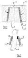
- FIGURE 7 illustrates how a metal structure 1 with the form of a frustum of a cone secures a catheter 6.
- a catheter 6 with a diameter substantially equal to the smallest diameter of the frusto-conical metal structure is put through the metal structure 1.
- An adhesive 14 can be easily inserted at the largest diameter of the metal structure 1 in order to secure the catheter 6 to the metal structure at its smallest side.
- a frusto-conical metal structure may have following dimensions, here given as a matter of example :
- the tubular metal structure according to the present invention can be used successfully as a heat exchanger.
- a fluid can be passed through the tubular structure which, for example, can transfer its heat to the fluid surrounding the metal structure.
- the outer wall of the tubular metal structure is very porous and thus has a large heat-exchange surface, which is very conducive to efficient heat-exchange.
Abstract
Description
- The present invention relates to a laminated sintered metal structure, a method for the manufacture thereof and, more particularly, a medical application therefor.
- Many applications require metal elements, e.g. tubular metal elements, which are porous and yet possess sufficient strength.
- Use of a porous flat metal fibre web, sintered or not, is known in various fields of application, e.g. for burners and filters. However, a structure obtained through the winding up of such fibre web has insufficient strength for many applications. In addition, it is disadvantageous for many applications that the core of the tubular element is not sealed off from the casing or, in other words, that the tube wall is radially porous.
- In USA-3,505,038 it is disclosed how a tubular filter element can be manufactured by combining a metal fibre web, sintered or not, with a metal wire net.
- EP-A-367 354 discloses a subcutaneous part which comprises a mesh sheet of sintered metallic fibers with diameter ranging between 2 and 25 µm, having a porosity ranging between 70 and 90%, and a holding member comprising a round hole provided with screw tread.
- It is an object of the present invention to provide a simple sintered metal structure which has a porous outer wall yet sufficient mechanical strength, and whereby the total wall of the structure is impermeable in the radial direction for the fluids contained in the tube.
It is another object of the present invention to provide a method for the manufacture of such a metal structure. - According to a first aspect of the present invention, there is provided a laminated or layered metal structure as defined in
claim 7. - Both components of the structure of claim 1 can be made of any metal or metal alloy whatever. Examples are steel, stainless steel or titanium.
- The radially outer component contains metal fibres that can be made by abrading the upper edge of a rolled metal foil, so-called Bekinit® fibres, as described in US-A-4,930,199, or using the bundled drawing technique, as described, e.g., in the patent US-A-3.379,000.
The metal fibres have an equivalent diameter ranging between 2 µm and 150 µm, preferably ranging between 40 µm and 80 µm. The equivalent diameter of a fibre is the diameter of an imaginary round fibre having the same cross-section as that of the real fibre concerned. - The metal fibres are then processed to form a contiguous porous fibre layer, for example in the form of a nonwoven web, a knitted, woven or wound fabric or mesh, or in the form of helicoidally and diagonally cross-wound metal fibre filaments.
- For specific applications, the metal structure is a tubular structure and can be provided with longitudinal anchoring or reinforcing ribs along the outer wall, which, among other things, would enhance its mechanical strength. Transverse anchoring or reinforcing ribs can also be provided around the outside of the tubular structure. Both the longitudinal ribs and the transversal ribs can be of a sintered metal fibre construction, e.g. a sintered steel, stainless steel or titanium fibre construction.
- The coated tubular structure according to the present invention can be made of completely bio-inert titanium, thus making the structure exceptionally useful for medical applications. An example of this will be discussed hereunder.
- In a preferable embodiment of the present invention, the metal structure has the form of a frustum of a cone. As will be explained hereinafter, such a form allows to have better sintered bonds between the individual steel fibres or steel filaments.
- According to a second aspect of the present invention, there is provided a method of manufacturing a metal structure according to the first aspect of the present invention.
For an embodiment of the metal structure where the radially outer component is a sintered nonwoven web, the method of manufacturing comprises the following steps : - (a) wrapping a metal foil around a core ;
- (b) wrapping a metal web around the metal foil ;
- (c) clamping the foil-web structure obtained in (b) in a mould ;
- d) sintering the clamped structure in a furnace.
-
- For an embodiment with two or more longitudinal ribs on the outer surface, the method of manufacturing comprises the following steps :
- (a) wrapping a metal foil around a core ;
- (b) wrapping a metal web around the metal foil ;
- (c) clamping the foil-web structure obtained in (b) in a mould with two or more longitudinal slits down the inner wall ;
- (d) sintering the clamped structure in a furnace.
-
- According to a third aspect of the present invention, there is provided the use of a metal structure according to the first aspect of the present invention as a heat exchanger.
- The present invention will now be explained in more detail referring to the following drawings.
- FIGURE 1 schematically represents a tubular metal structure according to the present invention, comprising a metal foil surrounded by a metal fibre web :
- FIGURE 2 schematically represents a tubular metal structure comprising a metal foil and a woven layer made of metal filament yarn ;
- FIGURE 3 schematically represents a tubular metal structure comprising a metal foil and a number of helicoidal metal fibre strips wound crosswise over each other ;
- FIGURE 4 shows a tubular metal structure that incorporates longitudinal reinforcement ribs ;
- FIGURE 5 illustrates how a tubular metal structure according to the present invention can be used as a securing element for a catheter as used in continuous ambulant peritoneal dialysis (CAPD) ;
- FIGURE 6 shows a way of manufacturing a metal structure which has the form of a frustum of a cone ;
- FIGURE 7 shows how a metal structure with the form of a frustum of a cone secures a catheter.
-
- Referring to FIGURE 1, a tubular metal structure 1 according to the first aspect of the present invention has two concentric metal components in the form of a cylinder: a radial
inner metal foil 2 and a surroundingcomponent 3 containing metal fibres. Stainless steel or titanium may be preferred according to the intended application. - The
metal foil 2 gives the required strength to the tubular metal structure and has a thickness ranging between 20 µm and 200 µm. Themetal foil 2 also renders the coated metal structure 1 impermeable to fluids and adhesives. - In a preferred embodiment, as shown in FIGURE 1, the surrounding component with metal fibres is a sintered
metal fibre web 3. The sintered metal fibre web has a porosity greater than 80%, e.g. greater than 85% or greater than 90%. - A method of manufacturing such a laminated tubular structure comprises the following steps :
- (a) wrapping the metal foil around a core of a tubular form ;
- (b) wrapping the metal web around the metal foil ;
- (c) clamping the foil-web structure obtained in (b) in a mould ;
- d) sintering the clamped structure in a furnace. The mould and the core around which the foil is wrapped may be made, e.g., of ceramic material. The wrapping of the metal foil in step (a) is done so that there is a zone of overlapping. During the sintering process (step (d)) the wrapped and partially overlapping metal foil functions as a type of spring and exerts some radially outward pressure on the metal web, which improves the strength of sintered bonds between the individual filaments.
-
- Step (a) may be replaced by fitting a pre-formed tubular metal structure such as a tube or a pipe over a core. In this alternative the advantage of supplemental radially outward pressure is lost, since a tube or a pipe does not function as a spring. This loss of pressure, however, can be compensated by adding some more web material.
- The intensity of the sintering treatment in step (d) of the above production method may vary according to the desired strength of the sintered bonds at the points of contact between the metal fibres.
- After the sintering treatment in step (d) a supplementary hot isostatic pressing treatment, a so called HIP treatment, may be applied, for example at a pressure of about 1000 bar, at a temperature of about 930 °C and in an environment of nearly pure argon gas (99.9999%). Such a supplementary HIP treatment improves the bonds which have been created between the individual fibres during sintering.
- In an alternative embodiment, shown in FIGURE 2, the metal structure 1 includes a
metal foil 2 and awoven layer 4 of continuous metal fibre bundles (marketed under the trade name Bekinit® ). - In a second alternative embodiment, shown in FIGURE 3, the metal structure 1 has 2 layers of
continuous fibre filaments 7,8 wound diagonally and sintered on to themetal foil 2. Such diagonal winding offers the advantage of a relatively open (porous) structure after sintering. - Depending on the intended applications and, inter alia, on the application explained in a following example, it may be advisable to make the tubular metal structure according to the present invention with two or more longitudinal reinforcing or securing
ribs 5 along the outer wall, as shown in FIGURE 4. - In a third alternative embodiment, the tubular metal structure according to the invention has an inner metal foil and a knitted tubular metal sleeve, as described in the PCT patent application WO 97/04152 by the applicant. This structure can be manufactured by slipping the knitted fabric over the tubular metal foil supported by means of a mandrel, clamping the knitted fabric in place, then sintering the structure thus obtained in an oven in a vacuum or using a protective inert gas (e.g. hydrogen gas).
- A tubular metal structure according to the first aspect of the present invention can be used as an implant for securing foreign bodies in organic tissue.
- Practical examples are the use of the metal structure as a fixing element for a catheter implanted in the human body in continuous ambulant peritoneal dialysis (CAPD) therapy and use of the structure as a fixing element for a central venous catheter (CVC) in the human body.
- The CAPD technique allows kidney patients to execute their dialysis independently in discrete, familiar surroundings. This is a major advantage in comparison with the haemodialysis technique, which usually involves a two-day stay in hospital.
- In the CAPD technique, the peritoneum acts as a dialysis membrane. A catheter - e.g. of silicon resin - is used to introduce a saline solution into the patient's abdominal cavity. The saline solution purifies the blood naturally by osmosis, the peritoneum acting as a semi-permeable membrane.
- EP-B-0 367 354 describes an implant consisting of a percutaneous section and a flat elastic metal fibre mesh. Implanting such an element would likewise require a double surgical operation, as described in
Column 4 / line 34 toColumn 5 /line 7. This is a substantial disadvantage that surgeons would prefer to avoid. - A CAPD (silicon) catheter is held in the body by tissue in-growth in one or more porous fixing element(s) mounted concentrically on the catheter, e.g. by means of a bio-compatible adhesive. These small elements also form a seal between the skin and the outside world. This is necessary in order to prevent the intrusion of bacteria that can lead to infections and inflammation of the peritoneum.
- Still according to the prior art, these elements are usually made of Dacron® (the so-called "Tenckhoff" catheters, commercially available under the trade mark Quinton® , Seattle, USA). This does, however, entail a number of problems. The Dacron® material is not completely bio-compatible, which can cause infections, necessitating discontinuation of the CAPD treatment.
A further problem is that tissue growth in the element is partially limited as the adhesive used to fix the Dacron® element to the catheter penetrates the Dacron® material radially outwards. This problem is described inChapter 4, pp. 76, 77 of the doctoral thesis "Titanium fibre mesh anchorage for percutaneous devices applicable for peritoneal dialysis", Paquay Y.C.G.J., Katholieke Universiteit Nijmegen (NL), 1996. - Referring to FIGURE 5, a tubular metal structure 1 according to the present invention including a titanium foil and a porous titanium fibre web is ideally suited for use as an anchorage for a
silicon catheter 6 and removes the disadvantages of the above Dacron® anchorage elements. It also gives the catheter a more solid support. - Titanium is known to be a biologically inert bio-compatible material. A coating with a basis of hydroxyl apatite may be applied to improve the biological characteristics of the metal further without impairing its physical properties.
The titanium foil also prevents the outward radial penetration of the adhesive on the catheter circumference in the highly porous titanium fibre web, which in no way impairs tissue in-growth in the web.
Finally, to obtain a good anchoring of the catheter in the human body, a tubular titanium structure can be used having two or more longitudinal ribs down the length of its outer surface, as described above. These ribs provide a certain mechanical anchorage before tissue in-growth takes place. - Before being used as anchorages for CAPD catheters, tubular titanium structures were made in conformity with the method described earlier, to lengths between 10 mm and 100 mm, having internal diameters of 2 mm to 20 mm and a total wall-thickness ranging from 1 mm to 10 mm.
- For practical purposes, a structure is made with a length of 16 mm, an internal diameter of 5 mm and an external diameter of 7.9 mm, with a titanium foil of a thickness of 50 µm and a titanium fibre web of 614 g/m2 with a basis of titanium fibres having an average equivalent diameter of 50 µm of a porosity of 90.8%. These anchorage elements are then pressed down on a silicon catheter and glued in place at the desired points.
- FIGURE 6 illustrates how a preferable embodiment of a metal structure according to a first aspect of the present invention can be made. Such a preferable embodiment has the form of a frustum of a cone.
Ametal foil 2 is wrapped around a conical core 8 and ametal fibre web 3 is wrapped around the wrappedfoil 2. Amould 10 with an internal conical wall is put upon the web-foil structure 2-3 and the whole is put in a sintering furnace. Acentral hole 12 is provided on top of the mould in order to allow for degassing. The weight of themould 10 creates a pressure P in the metal fibre web, which would not have been created in case the metal structure is purely cylindrical. Since higher pressures create better bonds between the filaments during sintering, this conical embodiment is likely to have better bonds between the individual steel filaments than in a cylindrical embodiment sintered under the same circumstances. - FIGURE 7 illustrates how a metal structure 1 with the form of a frustum of a cone secures a
catheter 6. Acatheter 6 with a diameter substantially equal to the smallest diameter of the frusto-conical metal structure is put through the metal structure 1. An adhesive 14 can be easily inserted at the largest diameter of the metal structure 1 in order to secure thecatheter 6 to the metal structure at its smallest side.
If used as an anchorage for CAPD catheters, such a frusto-conical metal structure may have following dimensions, here given as a matter of example : - height = 14 mm
- smallest (top) diameter = 5 mm
- greatest (bottom) diameter = 10 mm.
- The tubular metal structure according to the present invention can be used successfully as a heat exchanger. A fluid can be passed through the tubular structure which, for example, can transfer its heat to the fluid surrounding the metal structure. The outer wall of the tubular metal structure is very porous and thus has a large heat-exchange surface, which is very conducive to efficient heat-exchange.
Claims (16)
- Laminated metal structure including a radially outer component and a radially inner component concentrically interconnected with each other, the radially outer component having a porosity of at least 80 %, characterized in that the radially inner component is a radially impermeable metal tube with a wall thickness between 20 µm and 200 µm.
- Metal structure according to claim 1, wherein the radially inner component and the radially outer component are made of steel, stainless steel or titanium.
- A metal structure according to claim 1 or 2 wherein the metal tube is formed by a metal foil.
- A metal structure according to any one of the preceding claims wherein the radially outer component comprises sintered metal fibres.
- Metal structure according to claim 4, wherein the metal fibres have an equivalent diameter of between 2 µm and 150 µm.
- Metal structure according to claim 4 or 5, wherein the metal fibres have an equivalent diameter of between 40 µm and 80 µm.
- Metal structure according to claim 4, wherein the radially outer component is a sintered nonwoven metal web.
- Metal structure according to claim 7, provided with two or more longitudinal ribs along the outer surface.
- Metal structure according to claim 8, wherein the longitudinal ribs are of a sintered metal fibre construction.
- Metal structure according to claim 9, wherein the longitudinal ribs are of a sintered steel, stainless steel or titanium fibre construction.
- Metal structure according to claim 4, wherein the radially outer component is a knitted or woven mesh.
- Metal structure according to claim 4, wherein the radially outer component has a number of helicoidally and diagonally cross-wound metal fibre filaments.
- Metal structure according to any one of the preceding claims wherein the metal structure has the form of a frustum of a cone.
- Method of manufacturing a metal structure according to claim 7, said method comprising the following steps:(a) wrapping the metal foil around a core ;(b) wrapping the metal web around the metal foil ;(c) clamping the foil-web structure obtained in (b) in a mould ;d) sintering the clamped structure in a furnace.
- Method of manufacturing a metal structure according to claim 9, said method comprising the following steps:(a) wrapping the metal foil around a core;(b) wrapping the metal web around the metal foil;(c) clamping the foil-web structure obtained in (b) in a mould with two or more longitudinal slits down the inner wall ;(d) sintering the clamped structure in a furnace.
- Use of a metal structure according to any one of claims 1 to 13, as a heat exchanger.
Applications Claiming Priority (3)
| Application Number | Priority Date | Filing Date | Title |
|---|---|---|---|
| BE9700559A BE1011244A3 (en) | 1997-06-30 | 1997-06-30 | LAYERED TUBULAR METAL STRUCTURE. |
| BE9700559 | 1997-06-30 | ||
| PCT/EP1998/004042 WO1999001245A1 (en) | 1997-06-30 | 1998-06-22 | Laminated metal structure |
Publications (2)
| Publication Number | Publication Date |
|---|---|
| EP0996519A1 EP0996519A1 (en) | 2000-05-03 |
| EP0996519B1 true EP0996519B1 (en) | 2001-10-04 |
Family
ID=3890603
Family Applications (1)
| Application Number | Title | Priority Date | Filing Date |
|---|---|---|---|
| EP98936403A Expired - Lifetime EP0996519B1 (en) | 1997-06-30 | 1998-06-22 | Laminated metal structure |
Country Status (9)
| Country | Link |
|---|---|
| US (1) | US6379816B1 (en) |
| EP (1) | EP0996519B1 (en) |
| JP (2) | JP2002510232A (en) |
| AT (1) | ATE206339T1 (en) |
| BE (1) | BE1011244A3 (en) |
| BR (1) | BR9810370A (en) |
| DE (1) | DE69801915T2 (en) |
| ES (1) | ES2165691T3 (en) |
| WO (1) | WO1999001245A1 (en) |
Families Citing this family (27)
| Publication number | Priority date | Publication date | Assignee | Title |
|---|---|---|---|---|
| ES2265993T3 (en) * | 1999-09-17 | 2007-03-01 | Restore Medical, Inc. | IMPLANTS FOR THE TREATMENT OF RONQUIDS. |
| US7537664B2 (en) | 2002-11-08 | 2009-05-26 | Howmedica Osteonics Corp. | Laser-produced porous surface |
| EP1648348B1 (en) * | 2003-07-24 | 2015-06-17 | Tecomet Inc. | Assembled non-random foams |
| JP4524776B2 (en) * | 2004-04-14 | 2010-08-18 | 晶彦 千葉 | Method for producing porous body for living body |
| AU2006287772A1 (en) * | 2005-09-08 | 2007-03-15 | Incumed Llc | Method for bonding titanium based mesh to a titanium based substrate |
| US8728387B2 (en) | 2005-12-06 | 2014-05-20 | Howmedica Osteonics Corp. | Laser-produced porous surface |
| EP1997521A4 (en) * | 2006-03-17 | 2012-09-12 | Hi Lex Corp | Medical material |
| US7867283B2 (en) * | 2006-05-30 | 2011-01-11 | Boston Scientific Scimed, Inc. | Anti-obesity diverter structure |
| US20090041978A1 (en) * | 2007-02-05 | 2009-02-12 | Sogard David J | Synthetic composite structures |
| US9415567B2 (en) | 2007-02-05 | 2016-08-16 | Boston Scientific Scimed, Inc. | Synthetic composite structures |
| EP2203139A4 (en) * | 2007-10-12 | 2010-12-01 | Medical Res Products B Inc | Medical apparatus and method for facilitating the management of long term tunneled conduits |
| JP4996578B2 (en) * | 2008-10-28 | 2012-08-08 | 株式会社サンメディカル技術研究所 | Medical device or instrument comprising a porous structure |
| IT1398443B1 (en) * | 2010-02-26 | 2013-02-22 | Lima Lto S P A Ora Limacorporate Spa | INTEGRATED PROSTHETIC ELEMENT |
| US8974535B2 (en) * | 2010-06-11 | 2015-03-10 | Sunnybrook Health Sciences Centre | Method of forming patient-specific implant |
| JP5302273B2 (en) * | 2010-07-12 | 2013-10-02 | 株式会社サンメディカル技術研究所 | Medical device or instrument comprising a porous structure |
| GB201011815D0 (en) * | 2010-07-13 | 2010-08-25 | Ostomycure As | Surgical implant |
| TW201225997A (en) | 2010-08-20 | 2012-07-01 | Thoratec Corp | Assembly and method for stabilizing a percutaneous cable |
| US9050446B2 (en) * | 2010-11-16 | 2015-06-09 | Ethicon Endo-Surgery, Inc. | Port with conduit wraparound feature |
| JP2014516604A (en) * | 2011-03-24 | 2014-07-17 | シー・アール・バード・インコーポレーテッド | Immobilization and protection of implanted medical devices |
| JP5668187B2 (en) * | 2013-06-19 | 2015-02-12 | 株式会社サンメディカル技術研究所 | Medical device or instrument comprising a porous structure |
| CN105556642B (en) * | 2013-07-19 | 2017-10-31 | 国立大学法人名古屋工业大学 | Metal polishing pad and its manufacture method |
| US10086184B2 (en) | 2014-10-08 | 2018-10-02 | Alfred E. Mann Foundation For Scientific Research | Method of manufacturing percutaneous ports with wire coils |
| US10226612B2 (en) * | 2014-10-08 | 2019-03-12 | Alfred E. Mann Foundation For Scientific Research | Percutaneous ports with wire coils |
| JP6625873B2 (en) * | 2015-11-25 | 2019-12-25 | 富士フィルター工業株式会社 | Method for producing porous molded article, mold for molding, method for producing mold for molding, and laminate including porous member |
| US10596660B2 (en) | 2015-12-15 | 2020-03-24 | Howmedica Osteonics Corp. | Porous structures produced by additive layer manufacturing |
| US11628517B2 (en) | 2017-06-15 | 2023-04-18 | Howmedica Osteonics Corp. | Porous structures produced by additive layer manufacturing |
| AU2018256556B2 (en) | 2017-11-03 | 2024-04-04 | Howmedica Osteonics Corp. | Flexible construct for femoral reconstruction |
Family Cites Families (18)
| Publication number | Priority date | Publication date | Assignee | Title |
|---|---|---|---|---|
| US3505038A (en) | 1964-08-24 | 1970-04-07 | Brunswick Corp | Metal fibril compacts |
| US3379000A (en) | 1965-09-15 | 1968-04-23 | Roehr Prod Co Inc | Metal filaments suitable for textiles |
| US3852045A (en) * | 1972-08-14 | 1974-12-03 | Battelle Memorial Institute | Void metal composite material and method |
| US4488877A (en) * | 1982-08-23 | 1984-12-18 | Renal Systems, Inc. | Percutaneous implant for peritoneal dialysis |
| JPS6052851A (en) * | 1983-09-01 | 1985-03-26 | Toppan Printing Co Ltd | Color display method |
| DE3332348A1 (en) * | 1983-09-08 | 1985-04-04 | Kernforschungsanlage Jülich GmbH, 5170 Jülich | HYDROGEN PERMEATION WALL |
| SE445518B (en) * | 1985-02-27 | 1986-06-30 | Inst Applied Biotechnology | BUKVEGGSGENOMFORING |
| US4687471A (en) * | 1985-05-01 | 1987-08-18 | Curators Of The University Of Missouri | Peritoneal dialysis catheter |
| JPS62120403A (en) * | 1985-11-20 | 1987-06-01 | Permelec Electrode Ltd | Titanium composite body having porous surface and its manufacture |
| JPS62127489A (en) * | 1985-11-27 | 1987-06-09 | Permelec Electrode Ltd | Composite titanium body having coil-shaped surface skeleton structure and its production |
| DE3671407D1 (en) * | 1985-11-28 | 1990-06-28 | Bekaert Sa Nv | LAMINATED ITEM MADE OF METAL FIBER LAYERS. |
| CA1320616C (en) | 1987-12-09 | 1993-07-27 | Akira Yanagisawa | Fiber manufacturing method and apparatus therefor |
| US5098795A (en) * | 1988-08-10 | 1992-03-24 | Battelle Memorial Institute | Composite metal foil and ceramic fabric materials |
| NL8802685A (en) | 1988-11-02 | 1990-06-01 | Stichting Biomaterials Science | PERCUTANEOUS IMPLANT COMPRISING TWO COMPONENTS, AND A METHOD FOR IMPLANTING SUCH A PERCUTANEOUS IMPLANT IN SOFT TISSUES. |
| JP2580843B2 (en) * | 1990-06-07 | 1997-02-12 | 三菱電機株式会社 | Method for producing base material having porous surface |
| BE1006452A3 (en) * | 1992-12-18 | 1994-08-30 | Bekaert Sa Nv | Porous sintered laminate comprising metal fibers. |
| US5504300A (en) * | 1994-04-18 | 1996-04-02 | Zimmer, Inc. | Orthopaedic implant and method of making same |
| BE1009485A3 (en) | 1995-07-14 | 1997-04-01 | Bekaert Sa Nv | TEXTILE FABRIC INCLUDING MULTIPLE SCRAPED METAL filaments. |
-
1997
- 1997-06-30 BE BE9700559A patent/BE1011244A3/en not_active IP Right Cessation
-
1998
- 1998-06-22 DE DE69801915T patent/DE69801915T2/en not_active Expired - Fee Related
- 1998-06-22 BR BR9810370-9A patent/BR9810370A/en not_active IP Right Cessation
- 1998-06-22 AT AT98936403T patent/ATE206339T1/en not_active IP Right Cessation
- 1998-06-22 ES ES98936403T patent/ES2165691T3/en not_active Expired - Lifetime
- 1998-06-22 US US09/446,842 patent/US6379816B1/en not_active Expired - Fee Related
- 1998-06-22 WO PCT/EP1998/004042 patent/WO1999001245A1/en active IP Right Grant
- 1998-06-22 JP JP50632699A patent/JP2002510232A/en not_active Withdrawn
- 1998-06-22 EP EP98936403A patent/EP0996519B1/en not_active Expired - Lifetime
-
2009
- 2009-02-23 JP JP2009039137A patent/JP2009173037A/en active Pending
Also Published As
| Publication number | Publication date |
|---|---|
| JP2002510232A (en) | 2002-04-02 |
| EP0996519A1 (en) | 2000-05-03 |
| WO1999001245A1 (en) | 1999-01-14 |
| ATE206339T1 (en) | 2001-10-15 |
| JP2009173037A (en) | 2009-08-06 |
| ES2165691T3 (en) | 2002-03-16 |
| DE69801915T2 (en) | 2002-03-28 |
| BR9810370A (en) | 2000-09-05 |
| DE69801915D1 (en) | 2001-11-08 |
| BE1011244A3 (en) | 1999-06-01 |
| US6379816B1 (en) | 2002-04-30 |
Similar Documents
| Publication | Publication Date | Title |
|---|---|---|
| EP0996519B1 (en) | Laminated metal structure | |
| US11602446B2 (en) | Self-sealing tubular grafts, patches, and methods for making and using them | |
| US20080312577A1 (en) | Expandable dialysis apparatus and method | |
| JP2739878B2 (en) | Reinforced implant assembly and method of making the same | |
| US9855131B2 (en) | Vascular grafts with multiple channels and methods for making | |
| US4300244A (en) | Cardiovascular grafts | |
| US10653512B2 (en) | Electrospun PTFE coated stent and method of use | |
| JP4401165B2 (en) | Composite ePTFE / fiber prosthesis | |
| US5824050A (en) | Prosthesis with in-wall modulation | |
| JP4145143B2 (en) | Improved vascular prosthesis and method for manufacturing the same | |
| US5897587A (en) | Multi-stage prosthesis | |
| US4804382A (en) | Artificial vessel | |
| US6416537B1 (en) | Multi-stage prosthesis | |
| JP3570434B2 (en) | Stent and method for manufacturing the same | |
| JP2003511196A (en) | Stackable self-sealing vascular access graft | |
| AU2322897A (en) | Yarn wrapped ptfe tubular prosthesis | |
| EP1759721B1 (en) | Thin-walled vascular graft | |
| EP0164896B1 (en) | Percutaneous access device | |
| JPH02107268A (en) | Internal stay tube and preparation thereof | |
| EP0202917A2 (en) | Implant device | |
| JPH0516872B2 (en) | ||
| RO107819B1 (en) | Vascular prothesis and making process thereof |
Legal Events
| Date | Code | Title | Description |
|---|---|---|---|
| PUAI | Public reference made under article 153(3) epc to a published international application that has entered the european phase |
Free format text: ORIGINAL CODE: 0009012 |
|
| 17P | Request for examination filed |
Effective date: 19991207 |
|
| AK | Designated contracting states |
Kind code of ref document: A1 Designated state(s): AT BE CH DE ES FR GB IT LI LU NL |
|
| 17Q | First examination report despatched |
Effective date: 20000724 |
|
| GRAG | Despatch of communication of intention to grant |
Free format text: ORIGINAL CODE: EPIDOS AGRA |
|
| GRAG | Despatch of communication of intention to grant |
Free format text: ORIGINAL CODE: EPIDOS AGRA |
|
| GRAH | Despatch of communication of intention to grant a patent |
Free format text: ORIGINAL CODE: EPIDOS IGRA |
|
| GRAH | Despatch of communication of intention to grant a patent |
Free format text: ORIGINAL CODE: EPIDOS IGRA |
|
| GRAA | (expected) grant |
Free format text: ORIGINAL CODE: 0009210 |
|
| RIN1 | Information on inventor provided before grant (corrected) |
Inventor name: LOSFELD, RONNY Inventor name: DE LOOSE, BOUDEWIJN |
|
| AK | Designated contracting states |
Kind code of ref document: B1 Designated state(s): AT BE CH DE ES FR GB IT LI LU NL |
|
| PG25 | Lapsed in a contracting state [announced via postgrant information from national office to epo] |
Ref country code: IT Free format text: LAPSE BECAUSE OF FAILURE TO SUBMIT A TRANSLATION OF THE DESCRIPTION OR TO PAY THE FEE WITHIN THE PRE;WARNING: LAPSES OF ITALIAN PATENTS WITH EFFECTIVE DATE BEFORE 2007 MAY HAVE OCCURRED AT ANY TIME BEFORE 2007. THE CORRECT EFFECTIVE DATE MAY BE DIFFERENT FROM THE ONE RECORDED.SCRIBED TIME-LIMIT Effective date: 20011004 Ref country code: AT Free format text: LAPSE BECAUSE OF FAILURE TO SUBMIT A TRANSLATION OF THE DESCRIPTION OR TO PAY THE FEE WITHIN THE PRESCRIBED TIME-LIMIT Effective date: 20011004 |
|
| REF | Corresponds to: |
Ref document number: 206339 Country of ref document: AT Date of ref document: 20011015 Kind code of ref document: T |
|
| REG | Reference to a national code |
Ref country code: CH Ref legal event code: EP |
|
| REF | Corresponds to: |
Ref document number: 69801915 Country of ref document: DE Date of ref document: 20011108 |
|
| REG | Reference to a national code |
Ref country code: CH Ref legal event code: NV Representative=s name: KIRKER & CIE SA |
|
| REG | Reference to a national code |
Ref country code: GB Ref legal event code: IF02 |
|
| ET | Fr: translation filed | ||
| REG | Reference to a national code |
Ref country code: ES Ref legal event code: FG2A Ref document number: 2165691 Country of ref document: ES Kind code of ref document: T3 |
|
| PG25 | Lapsed in a contracting state [announced via postgrant information from national office to epo] |
Ref country code: LU Free format text: LAPSE BECAUSE OF NON-PAYMENT OF DUE FEES Effective date: 20020622 |
|
| PLBE | No opposition filed within time limit |
Free format text: ORIGINAL CODE: 0009261 |
|
| STAA | Information on the status of an ep patent application or granted ep patent |
Free format text: STATUS: NO OPPOSITION FILED WITHIN TIME LIMIT |
|
| 26N | No opposition filed | ||
| PGFP | Annual fee paid to national office [announced via postgrant information from national office to epo] |
Ref country code: ES Payment date: 20080626 Year of fee payment: 11 Ref country code: CH Payment date: 20080630 Year of fee payment: 11 |
|
| PGFP | Annual fee paid to national office [announced via postgrant information from national office to epo] |
Ref country code: NL Payment date: 20080624 Year of fee payment: 11 Ref country code: DE Payment date: 20080731 Year of fee payment: 11 |
|
| PGFP | Annual fee paid to national office [announced via postgrant information from national office to epo] |
Ref country code: FR Payment date: 20080617 Year of fee payment: 11 |
|
| PGFP | Annual fee paid to national office [announced via postgrant information from national office to epo] |
Ref country code: GB Payment date: 20080627 Year of fee payment: 11 |
|
| PGFP | Annual fee paid to national office [announced via postgrant information from national office to epo] |
Ref country code: BE Payment date: 20080730 Year of fee payment: 11 |
|
| BERE | Be: lapsed |
Owner name: S.A. *BEKAERT N.V. Effective date: 20090630 |
|
| REG | Reference to a national code |
Ref country code: CH Ref legal event code: PL |
|
| GBPC | Gb: european patent ceased through non-payment of renewal fee |
Effective date: 20090622 |
|
| NLV4 | Nl: lapsed or anulled due to non-payment of the annual fee |
Effective date: 20100101 |
|
| REG | Reference to a national code |
Ref country code: FR Ref legal event code: ST Effective date: 20100226 |
|
| PG25 | Lapsed in a contracting state [announced via postgrant information from national office to epo] |
Ref country code: LI Free format text: LAPSE BECAUSE OF NON-PAYMENT OF DUE FEES Effective date: 20090630 Ref country code: FR Free format text: LAPSE BECAUSE OF NON-PAYMENT OF DUE FEES Effective date: 20090630 Ref country code: CH Free format text: LAPSE BECAUSE OF NON-PAYMENT OF DUE FEES Effective date: 20090630 |
|
| PG25 | Lapsed in a contracting state [announced via postgrant information from national office to epo] |
Ref country code: GB Free format text: LAPSE BECAUSE OF NON-PAYMENT OF DUE FEES Effective date: 20090622 |
|
| PG25 | Lapsed in a contracting state [announced via postgrant information from national office to epo] |
Ref country code: DE Free format text: LAPSE BECAUSE OF NON-PAYMENT OF DUE FEES Effective date: 20100101 Ref country code: BE Free format text: LAPSE BECAUSE OF NON-PAYMENT OF DUE FEES Effective date: 20090630 |
|
| PG25 | Lapsed in a contracting state [announced via postgrant information from national office to epo] |
Ref country code: NL Free format text: LAPSE BECAUSE OF NON-PAYMENT OF DUE FEES Effective date: 20100101 |
|
| REG | Reference to a national code |
Ref country code: ES Ref legal event code: FD2A Effective date: 20090623 |
|
| PG25 | Lapsed in a contracting state [announced via postgrant information from national office to epo] |
Ref country code: ES Free format text: LAPSE BECAUSE OF NON-PAYMENT OF DUE FEES Effective date: 20090623 |