EP0996221A2 - Elektromotor und Stromversorgungseinheit mit verbesserter Bremscharakteristik - Google Patents
Elektromotor und Stromversorgungseinheit mit verbesserter Bremscharakteristik Download PDFInfo
- Publication number
- EP0996221A2 EP0996221A2 EP99203411A EP99203411A EP0996221A2 EP 0996221 A2 EP0996221 A2 EP 0996221A2 EP 99203411 A EP99203411 A EP 99203411A EP 99203411 A EP99203411 A EP 99203411A EP 0996221 A2 EP0996221 A2 EP 0996221A2
- Authority
- EP
- European Patent Office
- Prior art keywords
- braking
- windings
- motor
- power unit
- accordance
- Prior art date
- Legal status (The legal status is an assumption and is not a legal conclusion. Google has not performed a legal analysis and makes no representation as to the accuracy of the status listed.)
- Withdrawn
Links
Images
Classifications
-
- H—ELECTRICITY
- H02—GENERATION; CONVERSION OR DISTRIBUTION OF ELECTRIC POWER
- H02P—CONTROL OR REGULATION OF ELECTRIC MOTORS, ELECTRIC GENERATORS OR DYNAMO-ELECTRIC CONVERTERS; CONTROLLING TRANSFORMERS, REACTORS OR CHOKE COILS
- H02P3/00—Arrangements for stopping or slowing electric motors, generators, or dynamo-electric converters
- H02P3/06—Arrangements for stopping or slowing electric motors, generators, or dynamo-electric converters for stopping or slowing an individual dynamo-electric motor or dynamo-electric converter
Definitions
- the present invention relates to a universal type electric motor equipped with an improved structure for its electric braking upon turning off.
- the present invention also relates to a power unit employing the improved structure of this motor.
- the expedient of connecting the armature and field windings in parallel upon turning off of the motor is often used so that the electromotive counter-force generated produces rotor braking action.
- the expedient is particularly economical but has the drawback of creating an erratic braking effect producing an intolerable initial current peak which in the long term destroys bushes and switch, especially for fast motors with considerable kinetic rotor energy to dissipate.
- the general purpose of the present invention is to overcome the above shortcomings by supplying a universal motor with structure embodied to supply a satisfactory electrical braking effect. A power unit employing such an electric motor is also supplied.
- a universal electric motor comprising an armature and first field windings with a number N of turns and designed to be connected to a power source for motor rotation and second braking windings with at least 1.1 x N turns and designed to be connected in parallel with the armature to generate a braking field when power is removed from the motor.
- an electric power unit made up of a universal electric motor comprising an armature and first field windings with a number of turns N and a switch moving between a motor actuation position and a braking position with the motor comprising in addition second braking windings with at least 1.1 x N turns and the switch comprising contacts for connecting the field windings to a power supply line when it is in actuation position and for connecting the braking windings in parallel with the armature when in braking position.
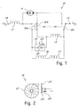
- FIG 1 shows a power unit 10.
- a universal electric motor comprising a rotor with armature 11 and a pair of field windings 12, 13.
- the motor also comprises a pair of additional braking windings 16, 17. It was found that these windings must have a number of loops 1.1 times and preferably 1.5 times and in particular more than 2 times the number of turns of the field windings. The choice of the exact value also depends on the magnetic characteristics of the lamination.
- the braking windings must have electrical resistance greater than that of the field windings to obtain an acceptable initial braking current without damage to the brushes and commutator. It has been found advantageous that the braking winding resistance be at least twice that of the field windings. For this purpose the diameter of the braking winding wire is adequately less than that of the wire used in the field windings.
- armature and field windings are designed to be connected in series together and powered by a single-phase electrical line as is normal for universal motors.
- the series of braking windings is designed to be placed in parallel with the armature when the series of field windings 12, 13 is disconnected from the mains. The braking windings thus generate a braking field which brakes the motor.
- the initial braking current is reduced and the magnetic braking flux is high and this ensures satisfactory steadiness of the braking effect.
- the filed windings are symmetrical. This considerable reduces radiofrequency disturbances in motor operation.
- a switch 18 which moves between a motor actuation position (shown in the FIG) and a braking position.
- the switch 18 comprises moving contacts 18a, 18b, 18c for connecting when in actuation position of the series made up of field windings and armature to the power line 14, 15 and when in braking position for connecting the braking windings in parallel with the armature and disconnecting the motor from the line.
- the power unit comprises a device 19 with an electrical contact 24 for delayed connection of at least one field winding 13 in parallel with the braking windings after operation of the switch towards the braking position.
- braking time is further reduced because after the first braking phase performed with only the braking windings and after motor rotation speed has fallen by a certain percentage the braking field, whose effectiveness is reduced because of speed reduction and therefore braking current reduction, is increased by means of the connection of the winding 13.
- connection delay can be secured by making the device 19 in the form of a timer started by passage of the switch 18 from the operating position to the motor braking position.
- the reference for connection of the winding is the time elapsed from the start of braking.
- the delayed connection device in the form of a device sensitive to motor rotation speed or braking current.
- This device makes the connection in parallel when motor rotation speed and/or braking current falls below a preset value under which braking becomes insufficient. It has been found particularly advantageous that operation of the connection device take place when rotor speed falls below half the nominal motor rotation speed or, in case of current measurement, that braking current become half the initial current value.
- the motor rotation speed sensitive device and the timer can be electronic or mechanical.
- Speed measurement can be direct or indirect like that performed with a speedometer dynamo or the like.
- the speed sensitive device can include an electronic circuit 20 sensitive to electrical voltage or current generated by the rotor during braking. This voltage or current depends on rotation speed.
- FIG 2 shows diagrammatically a mechanical embodiment of the device 19.
- a fan 21 is actuated by the motor to generate an air flow or a vacuum which acts on a blade 22 hinged at 23.
- the blade rests against the operating end of a normally closed microswitch 24 connected as shown in FIG 1 so that when motor rotation speed and hence the speed of the fan 21 is sufficient the air flow produced moves the blade until it actuates the switch 24 which is thus opened.
- speed falls below a preset value air flow is reduced and the switch can go into its closed position.
- the fan can even be the cooling fan with which the motor can be equipped. It is noted that upon starting the motor goes from speed zero to its nominal speed in a time sufficiently short to make the momentary presence of the braking windings in parallel with one of the two field windings ineffective. Use of the air flow to create a vacuum instead of pressure is easy to imagine.
Landscapes
- Engineering & Computer Science (AREA)
- Power Engineering (AREA)
- Stopping Of Electric Motors (AREA)
- Braking Arrangements (AREA)
Applications Claiming Priority (2)
| Application Number | Priority Date | Filing Date | Title |
|---|---|---|---|
| IT1998MI002263A IT1302719B1 (it) | 1998-10-21 | 1998-10-21 | Motore elettrico e gruppo motore con caratteristiche perfezionate difrenatura. |
| ITMI982263 | 1998-10-21 |
Publications (2)
| Publication Number | Publication Date |
|---|---|
| EP0996221A2 true EP0996221A2 (de) | 2000-04-26 |
| EP0996221A3 EP0996221A3 (de) | 2001-05-16 |
Family
ID=11380912
Family Applications (1)
| Application Number | Title | Priority Date | Filing Date |
|---|---|---|---|
| EP99203411A Withdrawn EP0996221A3 (de) | 1998-10-21 | 1999-10-18 | Elektromotor und Stromversorgungseinheit mit verbesserter Bremscharakteristik |
Country Status (2)
| Country | Link |
|---|---|
| EP (1) | EP0996221A3 (de) |
| IT (1) | IT1302719B1 (de) |
Family Cites Families (4)
| Publication number | Priority date | Publication date | Assignee | Title |
|---|---|---|---|---|
| DE4307356A1 (de) * | 1993-03-09 | 1994-09-15 | Bosch Gmbh Robert | Reihenschlußmotor, insbesondere Universalmotor, mit einer Bremseinrichtung |
| DE4333064A1 (de) * | 1993-09-29 | 1995-03-30 | Scintilla Ag | Bremsschaltung für einen Universalmotor |
| DE19651298C2 (de) * | 1996-12-10 | 1999-04-01 | Fein C & E | Reihenschlußmotor mit Kommutator und Bremswicklung |
| DE19702195C1 (de) * | 1997-01-23 | 1998-10-01 | Hans Hermann Rottmerhusen | Universalmotor mit einer Bremseinrichtung |
-
1998
- 1998-10-21 IT IT1998MI002263A patent/IT1302719B1/it active IP Right Grant
-
1999
- 1999-10-18 EP EP99203411A patent/EP0996221A3/de not_active Withdrawn
Also Published As
| Publication number | Publication date |
|---|---|
| ITMI982263A0 (it) | 1998-10-21 |
| EP0996221A3 (de) | 2001-05-16 |
| IT1302719B1 (it) | 2000-09-29 |
| ITMI982263A1 (it) | 2000-04-21 |
Similar Documents
| Publication | Publication Date | Title |
|---|---|---|
| EP0578366A2 (de) | Bremsvorrichtung für elektrische Motoren und insbesondere für tragbare Werkzeuge | |
| CN102484447B (zh) | 用于通用电动机的电动力的制动装置 | |
| JP2839589B2 (ja) | 直巻電動機の制動回路装置 | |
| GB2400990A (en) | Braking device for an electric motor | |
| US4395670A (en) | Hybrid electrical braking method and system for tool equipment having induction motor drives | |
| US5757154A (en) | Electric motor braking circuit arrangement | |
| JPS5829704B2 (ja) | 制動電動機 | |
| US4751414A (en) | Dynamic braking circuit for universal motor | |
| US4241302A (en) | Capacitive braking switching system for home appliances with induction motor drive | |
| US4853569A (en) | Noise suppression circuit for capacitor motors | |
| US20090230914A1 (en) | Motor Start Circuit with Capacitive Discharge Protection | |
| WO2004070913A2 (en) | Gas turbine engine starter generator with ac generator and dc motor modes | |
| EP0996221A2 (de) | Elektromotor und Stromversorgungseinheit mit verbesserter Bremscharakteristik | |
| WO1997043821A1 (en) | Method and device for braking an all-mains motor | |
| US7345437B2 (en) | Rechargeable vacuum with reduced AC voltage | |
| EP0367342B1 (de) | Steuerungseinrichtung für elektrische Mehrfachgeschwindigkeitsmotoren | |
| WO2002054567A3 (de) | Elektronisch kommutierter motor | |
| JP2005020995A (ja) | 駆動回路、特に巻き上げ機および/または走行装置用の駆動回路 | |
| US7508156B2 (en) | Electrical machine having a series chopper circuit | |
| JP3618697B2 (ja) | 電動工具のスイッチ回路 | |
| EP0283109B1 (de) | Anlasser für Einphasen-Induktionsmotoren | |
| KR100212215B1 (ko) | 전동차의 전원 제어 장치 | |
| US3538410A (en) | Starting control for electric motor | |
| KR100190139B1 (ko) | 압축기의 구동모터 전원접속제어장치 및 전원접속제어방법 | |
| EP0707756B1 (de) | Bremsen eines elektrischen motors |
Legal Events
| Date | Code | Title | Description |
|---|---|---|---|
| PUAI | Public reference made under article 153(3) epc to a published international application that has entered the european phase |
Free format text: ORIGINAL CODE: 0009012 |
|
| AK | Designated contracting states |
Kind code of ref document: A2 Designated state(s): CH DE FR GB IT LI SE |
|
| AX | Request for extension of the european patent |
Free format text: AL;LT;LV;MK;RO;SI |
|
| PUAL | Search report despatched |
Free format text: ORIGINAL CODE: 0009013 |
|
| AK | Designated contracting states |
Kind code of ref document: A3 Designated state(s): AT BE CH CY DE DK ES FI FR GB GR IE IT LI LU MC NL PT SE |
|
| AX | Request for extension of the european patent |
Free format text: AL;LT;LV;MK;RO;SI |
|
| RIC1 | Information provided on ipc code assigned before grant |
Free format text: 7H 02P 3/06 A, 7H 02P 3/22 B |
|
| 17P | Request for examination filed |
Effective date: 20011114 |
|
| AKX | Designation fees paid |
Free format text: CH DE FR GB IT LI SE |
|
| AXX | Extension fees paid |
Free format text: SI PAYMENT 20011114 |
|
| STAA | Information on the status of an ep patent application or granted ep patent |
Free format text: STATUS: THE APPLICATION IS DEEMED TO BE WITHDRAWN |
|
| 18D | Application deemed to be withdrawn |
Effective date: 20040503 |