EP0995975A1 - Fluid flow amount measuring apparatus responsive to fluid flow in forward and reverse directions - Google Patents
Fluid flow amount measuring apparatus responsive to fluid flow in forward and reverse directions Download PDFInfo
- Publication number
- EP0995975A1 EP0995975A1 EP99120754A EP99120754A EP0995975A1 EP 0995975 A1 EP0995975 A1 EP 0995975A1 EP 99120754 A EP99120754 A EP 99120754A EP 99120754 A EP99120754 A EP 99120754A EP 0995975 A1 EP0995975 A1 EP 0995975A1
- Authority
- EP
- European Patent Office
- Prior art keywords
- temperature
- intake air
- flow amount
- heater
- detector
- Prior art date
- Legal status (The legal status is an assumption and is not a legal conclusion. Google has not performed a legal analysis and makes no representation as to the accuracy of the status listed.)
- Withdrawn
Links
- 239000012530 fluid Substances 0.000 title claims description 41
- 238000011144 upstream manufacturing Methods 0.000 claims abstract description 34
- 230000004044 response Effects 0.000 claims abstract description 10
- 239000000758 substrate Substances 0.000 claims description 16
- 238000001514 detection method Methods 0.000 description 30
- 239000004065 semiconductor Substances 0.000 description 11
- 230000007423 decrease Effects 0.000 description 5
- 238000010586 diagram Methods 0.000 description 5
- 238000002485 combustion reaction Methods 0.000 description 4
- 230000004043 responsiveness Effects 0.000 description 4
- 230000035945 sensitivity Effects 0.000 description 4
- 230000000052 comparative effect Effects 0.000 description 3
- 230000010349 pulsation Effects 0.000 description 3
- 238000010276 construction Methods 0.000 description 2
- 230000003247 decreasing effect Effects 0.000 description 2
- 238000001816 cooling Methods 0.000 description 1
- 238000005530 etching Methods 0.000 description 1
- 238000010438 heat treatment Methods 0.000 description 1
- 229910052710 silicon Inorganic materials 0.000 description 1
- 239000010703 silicon Substances 0.000 description 1
- 239000007787 solid Substances 0.000 description 1
Images


Classifications
-
- G—PHYSICS
- G01—MEASURING; TESTING
- G01F—MEASURING VOLUME, VOLUME FLOW, MASS FLOW OR LIQUID LEVEL; METERING BY VOLUME
- G01F1/00—Measuring the volume flow or mass flow of fluid or fluent solid material wherein the fluid passes through a meter in a continuous flow
- G01F1/68—Measuring the volume flow or mass flow of fluid or fluent solid material wherein the fluid passes through a meter in a continuous flow by using thermal effects
- G01F1/696—Circuits therefor, e.g. constant-current flow meters
- G01F1/698—Feedback or rebalancing circuits, e.g. self heated constant temperature flowmeters
- G01F1/699—Feedback or rebalancing circuits, e.g. self heated constant temperature flowmeters by control of a separate heating or cooling element
Definitions
- the present invention relates to a flow amount measuring apparatus for measuring a fluid flow amount.
- a thermal-type flow amount meter is used as a flow amount measuring apparatus to measure an intake air amount of an internal combustion engine of automotive vehicles or the like.
- intake air pulsation increases when it is in a low rotational speed and high load condition.
- the intake air is like to flow in reverse through the intake valve when a piston moves upward.
- the air flowing in reverse also is detected as the intake air flow amount.
- the intake air flow amount which is sucked into a combustion chamber cannot be detected accurately.
- a flow amount meter disclosed in JP-B2-62-14705 measures an intake air flow amount by correcting an average flow amount based on engine operating condition parameters such as an engine rotational speed and a throttle opening degree, so that the fluid flow amount may be measured in consideration of the direction of fluid flow.
- engine operating condition parameters such as an engine rotational speed and a throttle opening degree
- the intake air flow amount cannot be measured with high accuracy, because the intake air pulsation accompanied by the reverse flow cannot be simply determined from the engine rotational speed and the throttle opening degree.
- a flow amount meter disclosed in JP-A-61-213728 determines that an intake air flow direction is reversed when a plurality of singular points of a function appears in detected flow amount values. It is however difficult to accurately detect the reversal of the intake air flow from the detection of the singular points of a function, because the pulsation in the intake air flow is influenced largely by the types of engines and intake air duct configurations.
- a flow amount meter disclosed in JP-A-1-185416 detects an intake air flow direction from a difference between detection signals of two heaters disposed at an upstream side and a down stream side of a planar substrate.
- a control circuit construction is complicated, because two control circuits are required to detect signals from each heater.
- a temperature change rate of each heater at the time of heating operation may differ from each other, because it is difficult to match control constants of the two control circuits. Errors will occur in the difference between the temperatures of the heaters, thus disabling an accurate detection of the intake air flow direction.
- Flow amount meters and flow speed sensors disclosed in JP-A-8-14978, JP-A-60-142268 and JP-A-6-160142 detects an intake air flow direction from a difference between detection signals of two temperature sensors which are disposed at an upstream side and a downstream side of a heater.
- a sensing part including an intake air temperature sensor becomes large and the heat capacity of the sensing part increases, because the temperature sensors are disposed upstream and downstream the heater. As a result, the detection sensitivity and responsiveness of the flow amount meter will be lessened.
- a flow amount meter disclosed in JP-A-10-62220 expands a measurable range and decreases a ratio of noise relative to an output by arranging a heater to surround a group of temperature measuring resistors and increasing a difference between the temperatures of temperature measuring resistors of the group disposed at an upstream side and a downstream side in the group with respect to a fluid flow direction.
- a sensing part becomes large and the heat capacity of the sensing part increases, because the heater surrounds the group of the temperature measuring resistors. As a result, the detection sensitivity and responsiveness of the flow amount meter will be lessened.
- a heater is strip-shaped in a manner that each strip turns at a plurality of points and has a width in a flow direction.
- the temperature of the heater is controlled to a reference temperature determined in correspondence with a temperature detected by a fluid temperature detector.
- a flow amount detector is disposed at only one of an upstream side and a downstream side of the heater with respect to one fluid flow direction, so that a fluid flow amount varying with a fluid flow direction is detected from the temperature detected by the flow amount detector.
- a flow amount detecting unit 10 is disposed in an engine intake duct (not shown).
- the flow amount detecting unit 10 comprises a semiconductor substrate 11 made of a silicon or the like.
- a cavity 11a is formed in the semiconductor 1 at a location where a flow amount detector 21 and a heater 30 are formed.
- An insulating film 12 covers a top surface of the semiconductor substrate 11 including the cavity 11a.
- the cavity 11a is formed by an anisotropic etching from a bottom surface side of the semiconductor substrate 11 to a boundary surface with the insulating film 12.
- An intake air temperature detector 20, flow amount detector 21 and heater 30 are formed in this order on the insulating film 12 from the upstream side (left side in the figures) in a forward direction in which the intake air normally flows to be sucked into combustion chambers (not shown).
- the intake air temperature detector 20 as a fluid temperature detector is a resistor which changes its resistance in response to the intake air temperature thereby detecting the temperature of the intake air flowing therethrough.
- the heater 30 is a heat-generating type resistor and is controlled, by a bridge circuit shown in Fig. 2, to a reference temperature which is a predetermined temperature higher than that of the intake air temperature detected by the intake air temperature detector 20.
- the intake air temperature detector 20 is disposed at an upstream position away from the heater 30 so that the heat of the heater 30 does not influence the temperature detection operation of the intake air temperature detector 20.
- the flow amount detector 21 is a resistor and disposed at the upstream side of the heater 30 with respect to the forward direction of the intake air flow. The flow amount detector 21 also changes its resistance to detect the intake air flow amount passing therethrough.
- the heater 30 is a thin strip type and turns at a plurality of locations in a manner that each strip cross perpendicularly to the intake air flow direction. It has a predetermined width in the intake air flow direction. Terminals 35 are provided to electrically connect the intake air temperature detector 20, the flow amount detector 21 and the heater 30 with an external electrical circuit.
- the intake air temperature detector 20, the flow amount detector 21 and the heater 30 are covered with an insulating film 13.
- the flow amount detecting unit 10 shown in Fig. 1 is connected to an external electrical circuit as shown in Fig. 2.
- the intake air temperature detector 20 and the heater 30 form a bridge circuit with resistors 41 and 42 of fixed resistances.
- the resistance of each resistor of the bridge circuit is determined so that the temperature of the heater 30 is maintained at a reference temperature which is predetermined temperature higher than that detected by the intake air temperature detector 20.
- the reference temperature increases and decreases in accordance with the intake air temperature detected by the intake air temperature detector 20.
- a comparator 43 produces a high level output to turn on a transistor 44 and supply an electrical current to the heater 30 so that the temperature of the heater 30 rises.
- the transistor 44 turns off in response to a low level output of the comparator 43 to interrupt the electrical current supplied to the heater 30.
- the temperature of the heater 30 is set, by the bridge circuit as constructed above, to the reference temperature which is predetermined temperature higher than that detected by the intake air temperature detector 20.
- a circuit which includes the flow amount detector 21, a resistor 45 having a fixed resistance, an amplifier 46 and the like is for outputting an amplified potential which varies with a ratio of resistances of the flow amount detector 21 and the resistor 45.
- the output of the amplifier 46 responsively changes.
- FIG. 3 A relation among a temperature distribution in the heater 30, a detection temperature of the flow amount detector 21 and the reference temperature are shown in Fig. 3.
- the temperature in the heater 30 at the upstream side of the intake air flow decreases below the reference temperature, because the intake air flow in the forward direction cools the upstream side of the heater 30 more than the downstream side.
- the total resistance of the heater 30 lowers, because the resistance at the upstream side decreases when the temperature of the upstream side lowers.
- the electrical current supplied to the heater 30 increases to raise the decreased total resistance, and the temperature at the downstream side of the intake air flow rises above the reference temperature.
- the total resistance of the heater 30 increases, because the resistance at the downstream side increases with the increase in the temperature at the downstream side.
- the temperature at the upstream side of the heater 30 is still maintained below the reference temperature, because the intake air flow continues to cool the upstream side.
- the heat transfer path along which the heat is transferred from the downstream side to the upstream side of the intake air flow in the heater 30 is long, and the heat is not transferred quickly from the downstream side to the upstream side of the intake air flow.
- the temperatures at the upstream side and the downstream side of the intake air flow in the heater 30 continues to be lower and higher than the reference temperature, respectively.
- the flow amount detector 21 is located close to the upstream side of the intake air flow of the heater 30 with respect to the forward direction of the intake air flow so that the temperature detected by the flow amount detector 21 becomes substantially equal to the temperature of the upstream side of the heater 30. That is, the detection temperature of the flow amount detector 21 is lower and higher than the reference temperature when the intake air flows in the forward direction and in the reverse direction, respectively.
- the larger difference between the detection temperature of the flow amount detector 21 and the reference temperature means the larger intake air flow amount irrespective of the intake air flow direction. Changes in the detection temperature of the flow amount detector 21 with respect to the intake air flow direction and the intake air flow amount are shown in Fig. 4.
- the characteristics of Fig. 4 showing changes in the detection temperature of the flow amount detector 21 changes with the intake air temperature, because the reference temperature changes with the detection temperature of the intake air temperature detector 20, that is, the intake air temperature.
- the control circuit shown in Fig. 2 thus detects the intake air flow amount while responding to the intake air flow direction under the condition that the intake air temperature does not change. Even under the condition that the intake air temperature changes, the intake air flow amount responsive to the intake air flow direction can be measured by, for instance, varying the other input potential of the amplifier 46, to which the potential of a junction 52 is applied, in response to the detection temperature of the intake air temperature detector 20 or the reference temperature of the heater 30.
- the intake air flow amount can be measured irrespective of changes in the intake air temperature by comparing the temperature detected by the flow amount detector 21 with the detection temperature of the intake air temperature detector 20 or the reference temperature of the heater 30. Because the reference temperature is set to be predetermined temperature higher than the detection temperature of the intake air temperature detector 20, the intake air flow amount responsive to the intake air flow direction can be measured by comparing either one of the temperatures with the detection temperature of the flow amount detector 21. It is also possible to measure the intake air flow amount by applying the potential signals of the junctions 50 and 52 to an ECU and retrieving a map data in the ECU.
- a flow amount meter unit in which flow amount detector are disposed upstream and downstream a heater is described for comparison with the first embodiment.
- an intake air temperature detector 110, a flow amount detector 112, a heater 111 and a flow amount detector 113 are disposed on a substrate 101 from the upstream side in the forward direction of intake air flow.
- the temperature of the heater 111 is controlled to be a predetermined temperature higher than that detected by the intake air temperature detector 110.
- the detection temperature of the flow amount detector 112 located upstream the heater 111 is lower than the detection temperature of the flow amount detector 113 located downstream the heater 111. Further, as long as the intake air flows in the reverse direction, the detection temperature of the flow amount detector 113 located upstream the heater 111 in the reverse direction is lower than the detection temperature of the flow amount detector 112 located downstream the heater 111.
- the heater 111 turns only at one point and its width in the intake air flow direction is narrow. As a result, there occurs substantially no difference in temperatures in the intake air flow direction and the temperature is set uniformly over the entire area. Therefore, the detection temperature of the flow amount detectors 112 and 113 are slightly lower than the reference temperature set in the heater 111, because of being cooled by the intake air flow.
- the relation of the detection temperature of the flow amount detector 112 relative to the intake air flow direction and the intake air flow amount is shown in Fig. 7.
- the detection temperature indicates the temperature of the flow amount detector 112 and the flow amount detector 113 when the intake air flows in the forward direction and in the reverse direction, respectively.
- the difference between the temperatures detected by the flow amount detectors is small, because the heater 111 has no substantial temperature difference in the intake air flow direction. Therefore, the intake air flow amount cannot be measured with high accuracy when the intake air flow amount is small.
- the detecting unit must be sized large to dispose the flow amount detectors 112 and 113 at the upstream side and the downstream side of the heater 111, respectively. As a result, the heat capacity of the unit 100 becomes large, and the detection sensitivity and the responsiveness become low.
- the heater 30 turns at plural points to cross in a direction perpendicular to the intake air flow and has the predetermined width in the intake air flow direction so that the length of the heat transfer path is extended in the intake air flow direction.
- the temperature at the upstream side in the heater 30 in the air flow direction becomes lower than the reference temperature because of cooling by the intake air flow.
- the temperature at the downstream side in the heater 30 in the air flow direction is increased above the reference temperature to maintain the reference temperature. This condition is maintained.
- the flow amount detecting unit 10 is thus sized small and its heat capacity is decreased, because the intake air flow amount and the intake air flow direction are detected by comparing the detection temperature of the flow amount detector 21 and the reference temperature.
- the difference between the detection temperature of the flow amount detector 21 and the reference temperature is made large, the intake air flow amount and the intake air flow direction are detected with high sensitivity and responsiveness even when changes in the temperature and the flow amount are small.
- a strip of heater 31 is turned at a plurality of points so that each strip extends in the intake air flow direction.
- the temperatures at the upstream side and the downstream side of the intake air flow in the heater 31 become lower and higher than the reference temperature, respectively. Therefore, the intake air flow amount responsive to the intake air flow direction are detected by detecting the temperature by the flow amount detector 21.
- the intake air temperature detector 20 is arranged so that the heat of the heater 30 does not influence the temperature detection operation. It may however occur that the temperature of the semiconductor substrate 11 and the intake air temperature under some engine operating conditions such as a dead soak, hot soak or the like condition. If the semiconductor substrate 11 is solid at a position underneath the intake air temperature detector 20, the temperature of the semiconductor substrate 11 influences the intake air temperature detector 20, thus disabling an accurate detection of the intake air temperature.
- a cavity 11b is formed in the semiconductor substrate 11 at the position underneath the intake air temperature sensor 20 so that the intake air temperature detector 20 is less influenced by the heat of the semiconductor substrate 11 and is enabled to detect the intake air temperature accurately.
- a pair of slits 14 are formed in the insulating films 12 and 13 in such a manner that the flow amount detector 21 and the heater 30 are interposed therebetween in the intake air flow direction.
- the slits 14 restrict the heat of the heater 30 from being transferred to the semiconductor substrate 11. As a result, the electrical power required for the heater 30 to generate heat is reduced.
- the flow amount detector 21 is disposed at the downstream side of the heater 30 with respect to the forward direction of the intake air flow.
- the relation between the reference temperature and the detection temperature of the flow amount detector 21 does not depend on whether the intake air flow direction is forward or reverse, but depends on whether the flow amount detector 21 is located at the upstream side or the downstream side of the intake air flow. Therefore, the intake air amount is measured even if the flow amount detector 21 is disposed at the downstream side of the heater 30 with respect to the forward direction of the intake air flow.
- the intake air temperature detectors 20 and 22 are disposed at locations where the heat of the heater 30 does not influence the intake air temperature detecting operations.
- the control circuit is constructed as shown in Fig. 13 so that the temperatures, that is, resistances, of the flow amount detector 21 and the intake air temperature detector 22 as the fluid temperature detector.
- the potential at the junction 52 between the intake air temperature detector 22 and the fluid amount detector 21 which changes its temperature in response to changes in the intake air temperature does not change. It rather changes in response to the intake air flow amount and the direction of the intake air flow which the fluid amount detector 21. Therefore, the intake air flow direction and the intake air flow amount are measured irrespective of changes in the intake air temperature by applying the potential at the junction 52 and a predetermined fixed potential to one and the other inputs of the amplifier 46, respectively.
- the circuit of the first embodiment shown in Fig. 2 is constructed to maintain the temperature of the heater 30 constant irrespective of changes in the intake air temperature. If the intake air flow amount detected by the flow amount detector 21 is not influenced by the changes in the intake air flow temperature, the intake air flow direction and the intake air flow amount are measured irrespective of the changes in the intake air temperature by maintaining the input potential applied to the other input of the amplifier 46 at a fixed potential. However, the intake air flow between the heater 30 and the flow amount detector 21 and the thermal conductivity of the semiconductor substrate 11 actually change with changes in the intake air temperature. Therefore, if the temperature of the heater 30 is set to the fixed temperature, the intake air flow amount detected solely from the temperature detected by the flow amount detector 21 is influenced by changes in the thermal conductivity caused by the intake air temperature.
- a resistor 60 of a fixed resistance between the intake air temperature detector 20 and the junction 50 The range of temperature changes of the heater 30 caused by the temperature changes of the intake air temperature detector 20 is narrowed in the case of using the resistor 60 than in the case of not using the same. Optimizing the resistance of the resistor 60 cancels out the changes in the thermal conductivity caused by the changes in the intake air temperature between the heater 30 and the flow amount detector 21 and the changes in the temperature of the heater 30. As a result, the intake air flow amount and the intake air flow direction are measured solely from the temperature detected by the flow amount detector 21.
- the intake air flow amount and the intake air flow direction are measured solely from the temperature detected by the flow amount detector 21.
- the resistor 60 thus compensate for changes in the thermal conductivity between the heater 30 and the flow amount detector 21.
- the intake air flow amount and the intake air flow direction are also measured even if the resistor 60 is not used in the circuit shown in Fig. 14 by optimizing the characteristics of the resistance changes relative to the temperature of the intake air temperature detector 20.
- the intake air temperature detector 20 in the circuit of the first embodiment shown in Fig. 2 is replaced with a resistor 61 of a fixed resistance so that the temperature of the heater 30 is set to a fixed temperature.
- the flow amount detector 21, the intake air temperature detector 22 and a resistor 62 of a fixed resistance are connected as shown in Fig. 15, and the potential at the junction between the flow amount detector 2 and the intake air temperature detector 22 is applied to one input of the amplifier 46.
- the other input potential of the amplifier 46 is fixed.
- the intake air flow amount detected solely from the temperature of the flow amount detector 21 changes in response to the intake air temperature because of changes in the thermal conductivity caused by the temperature of intake air flowing between the heater 30 and the flow amount detector 21. Therefore, the intake air flow amount responsive to the intake air flow direction is detected irrespective of the intake air temperature, by connecting as shown in Fig. 15 the intake air temperature detector 22 and the resistor 62 having an optimum resistance set in consideration of the changes in the thermal conductivity caused by the intake air temperature, and by applying the potential of the junction 52 and the fixed potential to one input and the other input of the amplifier 46, respectively.
- the intake air flow amount responsive to the intake air flow direction is measured even if the resistance 62 is removed from the circuit shown in Fig. 15 by optimally setting the characteristics of the resistance changes of the intake temperature detector 22 relative to temperature.
- the intake air flow amount is detected while taking into consideration the intake air flow direction by determining whether the temperature detected by the flow amount detector 21 is higher or lower than the reference temperature.
- the temperature detected by the flow amount detector 21 in response to changes in the distance between the flow amount detector 21 and the heater. For instance, if the flow amount detector 21 is distanced away from the heater, the temperature detected by the flow amount detector 21 may become lower than the reference temperature even if the flow amount detector 21 is located at the downstream side of the heater with respect to the intake air flow in the forward direction. Therefore, it is possible to compare the temperature detected by the flow amount detector 21 and a temperature different from the reference temperature but determined to variably change with the reference temperature based on the distance between the flow amount detector 21 and the heater 30.
- the present invention may also be applied to a device which measures gas flow amount other than air.
- a heater (30) is set to a reference temperature which is a predetermined temperature higher than an intake air temperature detector (20).
- a flow amount detector (21) is disposed at an upstream side of the heater with respect to a forward direction of an intake air flow.
- the heater is turned at a plurality of points in a direction perpendicular to the forward direction of the intake air flow and has a predetermined width in the intake air flow direction so that heat transfers less in the intake air flow direction in the heater. If the intake air flow direction reverses, the temperature distribution in the heater also reverses. As a result, an intake air amount varying in response to the air flow direction is detected by comparing the temperature of the flow amount detector with the reference temperature.
Landscapes
- Physics & Mathematics (AREA)
- Fluid Mechanics (AREA)
- General Physics & Mathematics (AREA)
- Measuring Volume Flow (AREA)
- Details Of Flowmeters (AREA)
Abstract
In a thermal-type air flow measuring apparatus, a heater
(30) is set to a reference temperature which is a predetermined
temperature higher than an intake air temperature detector (20).
A flow amount detector (21) is disposed at an upstream side of
the heater with respect to a forward direction of an intake air
flow. The heater is turned at a plurality of points in a direction
perpendicular to the forward direction of the intake air flow and
has a predetermined width in the intake air flow direction so that
heat transfers less in the intake air flow direction in the heater.
If the intake air flow direction reverses, the temperature
distribution in the heater also reverses. As a result, an intake
air amount varying in response to the air flow direction is detected
by comparing the temperature of the flow amount detector with the
reference temperature.

Description
- The present invention relates to a flow amount measuring apparatus for measuring a fluid flow amount.
- A thermal-type flow amount meter is used as a flow amount measuring apparatus to measure an intake air amount of an internal combustion engine of automotive vehicles or the like. In the engine of not more than four cylinders, intake air pulsation increases when it is in a low rotational speed and high load condition. When opening periods of an intake valve and an exhaust valve overlap when the intake air flow is pulsating, the intake air is like to flow in reverse through the intake valve when a piston moves upward. The air flowing in reverse also is detected as the intake air flow amount. As a result, the intake air flow amount which is sucked into a combustion chamber cannot be detected accurately.
- A flow amount meter disclosed in JP-B2-62-14705 measures an intake air flow amount by correcting an average flow amount based on engine operating condition parameters such as an engine rotational speed and a throttle opening degree, so that the fluid flow amount may be measured in consideration of the direction of fluid flow. However, the intake air flow amount cannot be measured with high accuracy, because the intake air pulsation accompanied by the reverse flow cannot be simply determined from the engine rotational speed and the throttle opening degree.
- A flow amount meter disclosed in JP-A-61-213728 determines that an intake air flow direction is reversed when a plurality of singular points of a function appears in detected flow amount values. It is however difficult to accurately detect the reversal of the intake air flow from the detection of the singular points of a function, because the pulsation in the intake air flow is influenced largely by the types of engines and intake air duct configurations.
- A flow amount meter disclosed in JP-A-1-185416 detects an intake air flow direction from a difference between detection signals of two heaters disposed at an upstream side and a down stream side of a planar substrate. However, a control circuit construction is complicated, because two control circuits are required to detect signals from each heater. In addition, a temperature change rate of each heater at the time of heating operation may differ from each other, because it is difficult to match control constants of the two control circuits. Errors will occur in the difference between the temperatures of the heaters, thus disabling an accurate detection of the intake air flow direction.
- Flow amount meters and flow speed sensors disclosed in JP-A-8-14978, JP-A-60-142268 and JP-A-6-160142 detects an intake air flow direction from a difference between detection signals of two temperature sensors which are disposed at an upstream side and a downstream side of a heater. However, a sensing part including an intake air temperature sensor becomes large and the heat capacity of the sensing part increases, because the temperature sensors are disposed upstream and downstream the heater. As a result, the detection sensitivity and responsiveness of the flow amount meter will be lessened.
- A flow amount meter disclosed in JP-A-10-62220 expands a measurable range and decreases a ratio of noise relative to an output by arranging a heater to surround a group of temperature measuring resistors and increasing a difference between the temperatures of temperature measuring resistors of the group disposed at an upstream side and a downstream side in the group with respect to a fluid flow direction. However, a sensing part becomes large and the heat capacity of the sensing part increases, because the heater surrounds the group of the temperature measuring resistors. As a result, the detection sensitivity and responsiveness of the flow amount meter will be lessened.
- It is an object of the invention to provide a small-sized flow amount measuring apparatus which detects a flow amount with high accuracy irrespective of fluid flow direction.
- According to the present invention, a heater is strip-shaped in a manner that each strip turns at a plurality of points and has a width in a flow direction. The temperature of the heater is controlled to a reference temperature determined in correspondence with a temperature detected by a fluid temperature detector. A flow amount detector is disposed at only one of an upstream side and a downstream side of the heater with respect to one fluid flow direction, so that a fluid flow amount varying with a fluid flow direction is detected from the temperature detected by the flow amount detector.
- The above and other objects, features and advantages of the present invention will become more apparent from the following detailed description made with reference to the accompanying drawings. In the drawings:
- Fig. 1A is a plan view showing a flow amount measuring apparatus according to a first embodiment of the present invention, and Fig. 1B is a sectional view showing the flow amount measuring apparatus along line IB-IB in Fig. 1A;
- Fig. 2 is a circuit diagram showing an equivalent circuit of the flow amount measuring apparatus according to the first embodiment;
- Fig. 3 is a graph showing a temperature distribution in the cases of an air flow in a forward direction and a reverse direction in the first embodiment;
- Fig. 4 is a characteristic graph showing a relation between the air flow and a flow amount detector in the case of the air flow in the forward direction and the reverse direction in the first embodiment;
- Fig. 5 A is a plan view showing a flow amount measuring apparatus according to a comparative example, and Fig. 5B is a sectional view showing the flow amount measuring apparatus along line VB-VB in Fig. 5A;
- Fig. 6 is a graph showing a temperature distribution in the cases of an air flow in a forward direction and a reverse direction in the comparative example;
- Fig. 7 is a characteristic diagram showing a relation between the air flow and a flow amount detector in the case of the air flow in the forward direction and the reverse direction in the comparative example;
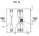
- Fig. 8 is a plan view showing a flow amount measuring apparatus according to a second embodiment of the present invention;
- Fig. 9A is a plan view showing a flow amount measuring apparatus according to a third embodiment of the present invention, and Fig. 9B is a sectional view showing the flow amount measuring apparatus taken along line IXB-IXB in Fig. 9A;
- Fig. 10A is a plan view showing a flow amount measuring apparatus according to a fourth embodiment of the present invention, and Fig. 10B is a sectional view showing the flow amount measuring apparatus along line XB-XB in Fig. 10A;
- Fig. 11 is a plan view showing a flow amount measuring apparatus according to a fifth embodiment of the present invention;
- Fig. 12A is a plan view showing a flow amount measuring apparatus according to a sixth embodiment of the present invention, and Fig. 12B is a sectional view of the flow amount measuring apparatus along line XIIB-XIIB in Fig. 12A;
- Fig. 13 is a circuit diagram showing an equivalent circuit of the flow amount measuring apparatus according to the sixth embodiment;
- Fig. 14 is a diagram showing an equivalent circuit of the flow amount measuring apparatus according to a seventh embodiment of the present invention; and
- Fig. 15 is a diagram showing an equivalent circuit of a flow amount measuring apparatus according to an eighth embodiment of the present invention.
-
- The present invention will be described with reference to various embodiments which are applied to an intake air amount measuring apparatus for internal combustion engines. The same reference numerals designate the same construction.
- Referring to Figs. 1A and 1B, a flow
amount detecting unit 10 is disposed in an engine intake duct (not shown). The flowamount detecting unit 10 comprises asemiconductor substrate 11 made of a silicon or the like. Acavity 11a is formed in the semiconductor 1 at a location where aflow amount detector 21 and aheater 30 are formed. Aninsulating film 12 covers a top surface of thesemiconductor substrate 11 including thecavity 11a. Thecavity 11a is formed by an anisotropic etching from a bottom surface side of thesemiconductor substrate 11 to a boundary surface with theinsulating film 12. An intakeair temperature detector 20,flow amount detector 21 andheater 30 are formed in this order on theinsulating film 12 from the upstream side (left side in the figures) in a forward direction in which the intake air normally flows to be sucked into combustion chambers (not shown). The intakeair temperature detector 20 as a fluid temperature detector is a resistor which changes its resistance in response to the intake air temperature thereby detecting the temperature of the intake air flowing therethrough. Theheater 30 is a heat-generating type resistor and is controlled, by a bridge circuit shown in Fig. 2, to a reference temperature which is a predetermined temperature higher than that of the intake air temperature detected by the intakeair temperature detector 20. The intakeair temperature detector 20 is disposed at an upstream position away from theheater 30 so that the heat of theheater 30 does not influence the temperature detection operation of the intakeair temperature detector 20. Theflow amount detector 21 is a resistor and disposed at the upstream side of theheater 30 with respect to the forward direction of the intake air flow. Theflow amount detector 21 also changes its resistance to detect the intake air flow amount passing therethrough. - As shown in Fig. 1A, the
heater 30 is a thin strip type and turns at a plurality of locations in a manner that each strip cross perpendicularly to the intake air flow direction. It has a predetermined width in the intake air flow direction.Terminals 35 are provided to electrically connect the intakeair temperature detector 20, theflow amount detector 21 and theheater 30 with an external electrical circuit. The intakeair temperature detector 20, theflow amount detector 21 and theheater 30 are covered with an insulatingfilm 13. - The flow
amount detecting unit 10 shown in Fig. 1 is connected to an external electrical circuit as shown in Fig. 2. The intakeair temperature detector 20 and theheater 30 form a bridge circuit withresistors heater 30 is maintained at a reference temperature which is predetermined temperature higher than that detected by the intakeair temperature detector 20. The reference temperature increases and decreases in accordance with the intake air temperature detected by the intakeair temperature detector 20. - When the temperature of the
heater 30 becomes lower than the reference temperature and its resistance decreases, a potential difference appears betweenjunctions comparator 43 produces a high level output to turn on atransistor 44 and supply an electrical current to theheater 30 so that the temperature of theheater 30 rises. When the temperature of theheater 30 reaches the reference temperature and its resistance increases, thetransistor 44 turns off in response to a low level output of thecomparator 43 to interrupt the electrical current supplied to theheater 30. The temperature of theheater 30 is set, by the bridge circuit as constructed above, to the reference temperature which is predetermined temperature higher than that detected by the intakeair temperature detector 20. - In Fig. 2, a circuit which includes the
flow amount detector 21, aresistor 45 having a fixed resistance, anamplifier 46 and the like is for outputting an amplified potential which varies with a ratio of resistances of theflow amount detector 21 and theresistor 45. As theflow amount detector 21 changes its temperature and hence its resistance in accordance with an intake air flow amount and an intake air flow direction, the output of theamplifier 46 responsively changes. - A relation among a temperature distribution in the
heater 30, a detection temperature of theflow amount detector 21 and the reference temperature are shown in Fig. 3. The temperature in theheater 30 at the upstream side of the intake air flow decreases below the reference temperature, because the intake air flow in the forward direction cools the upstream side of theheater 30 more than the downstream side. The total resistance of theheater 30 lowers, because the resistance at the upstream side decreases when the temperature of the upstream side lowers. The electrical current supplied to theheater 30 increases to raise the decreased total resistance, and the temperature at the downstream side of the intake air flow rises above the reference temperature. The total resistance of theheater 30 increases, because the resistance at the downstream side increases with the increase in the temperature at the downstream side. The temperature at the upstream side of theheater 30 is still maintained below the reference temperature, because the intake air flow continues to cool the upstream side. The heat transfer path along which the heat is transferred from the downstream side to the upstream side of the intake air flow in theheater 30 is long, and the heat is not transferred quickly from the downstream side to the upstream side of the intake air flow. As a result, the temperatures at the upstream side and the downstream side of the intake air flow in theheater 30 continues to be lower and higher than the reference temperature, respectively. - The
flow amount detector 21 is located close to the upstream side of the intake air flow of theheater 30 with respect to the forward direction of the intake air flow so that the temperature detected by theflow amount detector 21 becomes substantially equal to the temperature of the upstream side of theheater 30. That is, the detection temperature of theflow amount detector 21 is lower and higher than the reference temperature when the intake air flows in the forward direction and in the reverse direction, respectively. The larger difference between the detection temperature of theflow amount detector 21 and the reference temperature means the larger intake air flow amount irrespective of the intake air flow direction. Changes in the detection temperature of theflow amount detector 21 with respect to the intake air flow direction and the intake air flow amount are shown in Fig. 4. - Here, the characteristics of Fig. 4 showing changes in the detection temperature of the
flow amount detector 21 changes with the intake air temperature, because the reference temperature changes with the detection temperature of the intakeair temperature detector 20, that is, the intake air temperature. The control circuit shown in Fig. 2 thus detects the intake air flow amount while responding to the intake air flow direction under the condition that the intake air temperature does not change. Even under the condition that the intake air temperature changes, the intake air flow amount responsive to the intake air flow direction can be measured by, for instance, varying the other input potential of theamplifier 46, to which the potential of ajunction 52 is applied, in response to the detection temperature of the intakeair temperature detector 20 or the reference temperature of theheater 30. That is, the intake air flow amount can be measured irrespective of changes in the intake air temperature by comparing the temperature detected by theflow amount detector 21 with the detection temperature of the intakeair temperature detector 20 or the reference temperature of theheater 30. Because the reference temperature is set to be predetermined temperature higher than the detection temperature of the intakeair temperature detector 20, the intake air flow amount responsive to the intake air flow direction can be measured by comparing either one of the temperatures with the detection temperature of theflow amount detector 21. It is also possible to measure the intake air flow amount by applying the potential signals of thejunctions - Here, a flow amount meter unit in which flow amount detector are disposed upstream and downstream a heater is described for comparison with the first embodiment. As shown in Figs. 5A and 5B, in a
unit 100, an intakeair temperature detector 110, aflow amount detector 112, aheater 111 and aflow amount detector 113 are disposed on asubstrate 101 from the upstream side in the forward direction of intake air flow. The temperature of theheater 111 is controlled to be a predetermined temperature higher than that detected by the intakeair temperature detector 110. - As shown in Fig. 6, as long as the intake air flows in the forward direction, the detection temperature of the
flow amount detector 112 located upstream theheater 111 is lower than the detection temperature of theflow amount detector 113 located downstream theheater 111. Further, as long as the intake air flows in the reverse direction, the detection temperature of theflow amount detector 113 located upstream theheater 111 in the reverse direction is lower than the detection temperature of theflow amount detector 112 located downstream theheater 111. Theheater 111 turns only at one point and its width in the intake air flow direction is narrow. As a result, there occurs substantially no difference in temperatures in the intake air flow direction and the temperature is set uniformly over the entire area. Therefore, the detection temperature of theflow amount detectors heater 111, because of being cooled by the intake air flow. - The relation of the detection temperature of the
flow amount detector 112 relative to the intake air flow direction and the intake air flow amount is shown in Fig. 7. The detection temperature indicates the temperature of theflow amount detector 112 and theflow amount detector 113 when the intake air flows in the forward direction and in the reverse direction, respectively. As understood from Fig. 7, the difference between the temperatures detected by the flow amount detectors is small, because theheater 111 has no substantial temperature difference in the intake air flow direction. Therefore, the intake air flow amount cannot be measured with high accuracy when the intake air flow amount is small. Further, the detecting unit must be sized large to dispose theflow amount detectors heater 111, respectively. As a result, the heat capacity of theunit 100 becomes large, and the detection sensitivity and the responsiveness become low. - According to the first embodiment, however, the
heater 30 turns at plural points to cross in a direction perpendicular to the intake air flow and has the predetermined width in the intake air flow direction so that the length of the heat transfer path is extended in the intake air flow direction. As a result, the temperature at the upstream side in theheater 30 in the air flow direction becomes lower than the reference temperature because of cooling by the intake air flow. The temperature at the downstream side in theheater 30 in the air flow direction is increased above the reference temperature to maintain the reference temperature. This condition is maintained. The flowamount detecting unit 10 is thus sized small and its heat capacity is decreased, because the intake air flow amount and the intake air flow direction are detected by comparing the detection temperature of theflow amount detector 21 and the reference temperature. In addition, because the difference between the detection temperature of theflow amount detector 21 and the reference temperature is made large, the intake air flow amount and the intake air flow direction are detected with high sensitivity and responsiveness even when changes in the temperature and the flow amount are small. - In a second embodiment shown in Fig. 8, a strip of
heater 31 is turned at a plurality of points so that each strip extends in the intake air flow direction. In thisheater 31, the temperatures at the upstream side and the downstream side of the intake air flow in theheater 31 become lower and higher than the reference temperature, respectively. Therefore, the intake air flow amount responsive to the intake air flow direction are detected by detecting the temperature by theflow amount detector 21. - In a third embodiment, the intake
air temperature detector 20 is arranged so that the heat of theheater 30 does not influence the temperature detection operation. It may however occur that the temperature of thesemiconductor substrate 11 and the intake air temperature under some engine operating conditions such as a dead soak, hot soak or the like condition. If thesemiconductor substrate 11 is solid at a position underneath the intakeair temperature detector 20, the temperature of thesemiconductor substrate 11 influences the intakeair temperature detector 20, thus disabling an accurate detection of the intake air temperature. - For this reason, as shown in Figs. 9A and 9B, a
cavity 11b is formed in thesemiconductor substrate 11 at the position underneath the intakeair temperature sensor 20 so that the intakeair temperature detector 20 is less influenced by the heat of thesemiconductor substrate 11 and is enabled to detect the intake air temperature accurately. - In a fourth embodiment shown in Figs. 10A and 10B, a pair of
slits 14 are formed in the insulatingfilms flow amount detector 21 and theheater 30 are interposed therebetween in the intake air flow direction. Theslits 14 restrict the heat of theheater 30 from being transferred to thesemiconductor substrate 11. As a result, the electrical power required for theheater 30 to generate heat is reduced. - In a fifth embodiment shown in Fig. 11, the
flow amount detector 21 is disposed at the downstream side of theheater 30 with respect to the forward direction of the intake air flow. The relation between the reference temperature and the detection temperature of theflow amount detector 21 does not depend on whether the intake air flow direction is forward or reverse, but depends on whether theflow amount detector 21 is located at the upstream side or the downstream side of the intake air flow. Therefore, the intake air amount is measured even if theflow amount detector 21 is disposed at the downstream side of theheater 30 with respect to the forward direction of the intake air flow. - In a sixth embodiment shown in Figs. 12A, 12B and 13, the intake
air temperature detectors heater 30 does not influence the intake air temperature detecting operations. The control circuit is constructed as shown in Fig. 13 so that the temperatures, that is, resistances, of theflow amount detector 21 and the intakeair temperature detector 22 as the fluid temperature detector. The potential at thejunction 52 between the intakeair temperature detector 22 and thefluid amount detector 21 which changes its temperature in response to changes in the intake air temperature does not change. It rather changes in response to the intake air flow amount and the direction of the intake air flow which thefluid amount detector 21. Therefore, the intake air flow direction and the intake air flow amount are measured irrespective of changes in the intake air temperature by applying the potential at thejunction 52 and a predetermined fixed potential to one and the other inputs of theamplifier 46, respectively. - It is considered that the circuit of the first embodiment shown in Fig. 2 is constructed to maintain the temperature of the
heater 30 constant irrespective of changes in the intake air temperature. If the intake air flow amount detected by theflow amount detector 21 is not influenced by the changes in the intake air flow temperature, the intake air flow direction and the intake air flow amount are measured irrespective of the changes in the intake air temperature by maintaining the input potential applied to the other input of theamplifier 46 at a fixed potential. However, the intake air flow between theheater 30 and theflow amount detector 21 and the thermal conductivity of thesemiconductor substrate 11 actually change with changes in the intake air temperature. Therefore, if the temperature of theheater 30 is set to the fixed temperature, the intake air flow amount detected solely from the temperature detected by theflow amount detector 21 is influenced by changes in the thermal conductivity caused by the intake air temperature. - For this reason, according to a seventh embodiment shown in Fig. 14, a
resistor 60 of a fixed resistance between the intakeair temperature detector 20 and thejunction 50. The range of temperature changes of theheater 30 caused by the temperature changes of the intakeair temperature detector 20 is narrowed in the case of using theresistor 60 than in the case of not using the same. Optimizing the resistance of theresistor 60 cancels out the changes in the thermal conductivity caused by the changes in the intake air temperature between theheater 30 and theflow amount detector 21 and the changes in the temperature of theheater 30. As a result, the intake air flow amount and the intake air flow direction are measured solely from the temperature detected by theflow amount detector 21. That is, even if the other input potential of theamplifier 46 is fixed, the intake air flow amount and the intake air flow direction are measured solely from the temperature detected by theflow amount detector 21. Theresistor 60 thus compensate for changes in the thermal conductivity between theheater 30 and theflow amount detector 21. The intake air flow amount and the intake air flow direction are also measured even if theresistor 60 is not used in the circuit shown in Fig. 14 by optimizing the characteristics of the resistance changes relative to the temperature of the intakeair temperature detector 20. - In an eighth embodiment shown in Fig. 15, the intake
air temperature detector 20 in the circuit of the first embodiment shown in Fig. 2 is replaced with aresistor 61 of a fixed resistance so that the temperature of theheater 30 is set to a fixed temperature. Theflow amount detector 21, the intakeair temperature detector 22 and aresistor 62 of a fixed resistance are connected as shown in Fig. 15, and the potential at the junction between the flow amount detector 2 and the intakeair temperature detector 22 is applied to one input of theamplifier 46. The other input potential of theamplifier 46 is fixed. - If the temperature of the
heater 30 is set to the fixed temperature, the intake air flow amount detected solely from the temperature of theflow amount detector 21 changes in response to the intake air temperature because of changes in the thermal conductivity caused by the temperature of intake air flowing between theheater 30 and theflow amount detector 21. Therefore, the intake air flow amount responsive to the intake air flow direction is detected irrespective of the intake air temperature, by connecting as shown in Fig. 15 the intakeair temperature detector 22 and theresistor 62 having an optimum resistance set in consideration of the changes in the thermal conductivity caused by the intake air temperature, and by applying the potential of thejunction 52 and the fixed potential to one input and the other input of theamplifier 46, respectively. The intake air flow amount responsive to the intake air flow direction is measured even if theresistance 62 is removed from the circuit shown in Fig. 15 by optimally setting the characteristics of the resistance changes of theintake temperature detector 22 relative to temperature. - In the foregoing embodiments for implementing the present invention, the intake air flow amount is detected while taking into consideration the intake air flow direction by determining whether the temperature detected by the
flow amount detector 21 is higher or lower than the reference temperature. However, the temperature detected by theflow amount detector 21 in response to changes in the distance between theflow amount detector 21 and the heater. For instance, if theflow amount detector 21 is distanced away from the heater, the temperature detected by theflow amount detector 21 may become lower than the reference temperature even if theflow amount detector 21 is located at the downstream side of the heater with respect to the intake air flow in the forward direction. Therefore, it is possible to compare the temperature detected by theflow amount detector 21 and a temperature different from the reference temperature but determined to variably change with the reference temperature based on the distance between theflow amount detector 21 and theheater 30. - Though the above description is made with reference to a device which measures the intake air flow amount of the engine in the above plural embodiments, the present invention may also be applied to a device which measures gas flow amount other than air.
- In a thermal-type air flow measuring apparatus, a heater (30) is set to a reference temperature which is a predetermined temperature higher than an intake air temperature detector (20). A flow amount detector (21) is disposed at an upstream side of the heater with respect to a forward direction of an intake air flow. The heater is turned at a plurality of points in a direction perpendicular to the forward direction of the intake air flow and has a predetermined width in the intake air flow direction so that heat transfers less in the intake air flow direction in the heater. If the intake air flow direction reverses, the temperature distribution in the heater also reverses. As a result, an intake air amount varying in response to the air flow direction is detected by comparing the temperature of the flow amount detector with the reference temperature.
Claims (10)
- A flow amount measuring apparatus comprising:a fluid temperature detector (20, 22) for detecting a fluid temperature;a heater (30, 31) controllable to a reference temperature which is either one of a fixed temperature and a variable temperature responsive to the fluid temperature detected by the fluid temperature detector;a flow amount detector (21) disposed at either one of an upstream side and a downstream side of the heater with respect to a direction of fluid flow and changes its temperature in response to the fluid flow amount and the fluid flow direction; anddetecting means (46) for detecting the fluid flow amount variable with the fluid flow direction from the temperature detected by the fluid amount detector.
- A fluid amount measuring apparatus of claim 1, wherein:the detecting means (46) is for producing an output corresponding to a difference between the temperature detected by the fluid amount detector and a fixed temperature.
- A flow amount measuring apparatus of claim 1, wherein:the detecting means (46) is for producing an output corresponding to a difference between the temperature detected by the fluid amount detector and the temperature detected by the fluid temperature detector.
- A flow amount measuring apparatus of claim 1, wherein:the flow amount detector (21) is disposed upstream the heater with respect to a forward direction of a fluid flow;the detecting means (46) is for producing an output varying in dependence on the fluid flow in the forward direction and in a reverse direction when the temperature detected by the flow amount detector is lower and higher than a predetermined temperature, and varying in dependence on a temperature difference between the predetermined temperature and the temperature detected by the flow amount detector.
- A flow amount measuring apparatus of claim 1, wherein:the flow amount detector (21) is disposed downstream the heater with respect to the forward direction of a fluid flow;the detecting means (46) is for producing an output varying in dependence on the fluid flow in a reverse direction and in the forward direction when the temperature detected by the flow amount detector is lower and higher than a predetermined temperature, respectively, and varying in dependence on a temperature difference between the predetermined temperature and the temperature detected by the flow amount detector.
- A flow amount measuring apparatus of any one of claims 1 to 5, wherein:a temperature of the heater (30, 31) at one of an upstream side and a downstream side and another of the upstream side and the downstream side is lower and higher than the reference temperature, respectively.
- A flow amount measuring apparatus of any one of claims 1 to 6, wherein:the flow amount detector (21) is disposed to be capable of detecting a temperature which is lower and higher than the reference temperature when the fluid flow is in a direction from the flow amount detector to the heater and in a direction from the heater to the flow amount detector, respectively.
- A flow amount measuring apparatus of any one of claims 1 to 7, wherein:the heater (30, 31) includes a strip which turns at a plurality of points to have a total width larger than that of the fluid temperature detector and the fluid amount detector.
- A flow amount measuring apparatus of any one of claims 1 to 8, further comprising:a substrate (11) on which the fluid temperature detector (20, 22), the fluid amount detector (21) and the heater (30, 31) are formed, the substrate (11) having a cavity (11b) underneath the fluid temperature detector.
- A flow amount measuring apparatus of any one of claims 1 to 8, further comprising:a substrate (11) on which the fluid temperature detector (20, 22), the fluid amount detector (21) and the heater (30, 31) are formed, the substrate having slits (14) at the upstream side of the flow amount detector and the downstream side of the heater.
Applications Claiming Priority (4)
| Application Number | Priority Date | Filing Date | Title |
|---|---|---|---|
| JP29935398 | 1998-10-21 | ||
| JP29935398 | 1998-10-21 | ||
| JP29051799A JP3981907B2 (en) | 1998-10-21 | 1999-10-13 | Flow measuring device |
| JP29051799 | 1999-10-13 |
Publications (1)
| Publication Number | Publication Date |
|---|---|
| EP0995975A1 true EP0995975A1 (en) | 2000-04-26 |
Family
ID=26558102
Family Applications (1)
| Application Number | Title | Priority Date | Filing Date |
|---|---|---|---|
| EP99120754A Withdrawn EP0995975A1 (en) | 1998-10-21 | 1999-10-20 | Fluid flow amount measuring apparatus responsive to fluid flow in forward and reverse directions |
Country Status (3)
| Country | Link |
|---|---|
| US (1) | US6862930B1 (en) |
| EP (1) | EP0995975A1 (en) |
| JP (1) | JP3981907B2 (en) |
Cited By (3)
| Publication number | Priority date | Publication date | Assignee | Title |
|---|---|---|---|---|
| US6840102B2 (en) | 2002-02-19 | 2005-01-11 | Denso Corporation | Flow amount measuring apparatus |
| EP1790954A3 (en) * | 2000-07-27 | 2007-07-04 | Hitachi, Ltd. | Air flow sensor |
| NL2002633C2 (en) * | 2009-03-17 | 2010-09-20 | Uptime Products B V | METHOD AND APPARATUS FOR DETERMINING THE COLD AIR BALANCE IN A CONDITIONED SPACE WITH ICT EQUIPMENT. |
Families Citing this family (9)
| Publication number | Priority date | Publication date | Assignee | Title |
|---|---|---|---|---|
| JP3981907B2 (en) | 1998-10-21 | 2007-09-26 | 株式会社デンソー | Flow measuring device |
| JP4474771B2 (en) | 2000-12-20 | 2010-06-09 | 株式会社デンソー | Flow measuring device |
| EP1418408B1 (en) | 2001-08-14 | 2014-07-09 | Hitachi, Ltd. | Thermal flow sensor |
| US7360416B2 (en) * | 2005-07-07 | 2008-04-22 | Ricoh Company, Ltd. | Non-contact condensation detecting apparatus |
| US7255001B1 (en) * | 2006-07-25 | 2007-08-14 | Honeywell International Inc. | Thermal fluid flow sensor and method of forming same technical field |
| JP4479744B2 (en) * | 2007-04-27 | 2010-06-09 | 株式会社デンソー | Flow measuring device |
| JP5454603B2 (en) * | 2011-05-18 | 2014-03-26 | 株式会社デンソー | Flow measuring device |
| JP5680178B1 (en) * | 2013-12-26 | 2015-03-04 | 三菱電機株式会社 | Flow sensor and control system for internal combustion engine |
| JP7050591B2 (en) * | 2018-06-15 | 2022-04-08 | アズビル株式会社 | Thermal flow meter |
Citations (6)
| Publication number | Priority date | Publication date | Assignee | Title |
|---|---|---|---|---|
| EP0285451A1 (en) * | 1987-03-31 | 1988-10-05 | Sharp Kabushiki Kaisha | A flow sensor |
| US4884443A (en) * | 1987-12-23 | 1989-12-05 | Siemens-Bendix Automotive Electronics L. P. | Control and detection circuitry for mass airflow sensors |
| US5369994A (en) * | 1992-07-21 | 1994-12-06 | Robert Bosch Gmbh | Flow sensor |
| GB2285511A (en) | 1993-12-13 | 1995-07-12 | Siemens Ag | Method and device for measuring intake air mass |
| US5635635A (en) * | 1993-11-18 | 1997-06-03 | Unisia Jecs Corporation | Method and apparatus for detecting the intake air quantity of an engine |
| US5780735A (en) | 1995-02-15 | 1998-07-14 | Hitachi, Ltd. | Air flow rate measurement apparatus |
Family Cites Families (18)
| Publication number | Priority date | Publication date | Assignee | Title |
|---|---|---|---|---|
| JPS56162014A (en) * | 1980-05-16 | 1981-12-12 | Nippon Denso Co Ltd | Measuring device for flow rate of gas |
| US4501144A (en) | 1982-09-30 | 1985-02-26 | Honeywell Inc. | Flow sensor |
| JPS601525A (en) | 1983-06-20 | 1985-01-07 | Nippon Soken Inc | Semiconductor type flow-rate detecting device |
| JPS60142268A (en) | 1983-12-27 | 1985-07-27 | 株式会社山武 | Flow rate sensor |
| DE3509118C2 (en) | 1985-03-14 | 1994-03-24 | Bosch Gmbh Robert | Method and device for measuring the throughput of a medium flowing through a pipe |
| JPS6214705A (en) | 1985-07-12 | 1987-01-23 | 山本 博康 | Seedling transplanting jig |
| JPH01185416A (en) | 1988-01-20 | 1989-07-25 | Mitsubishi Electric Corp | Thermal flowmeter for internal combustion engine |
| JPH0244211A (en) * | 1988-08-04 | 1990-02-14 | Sharp Corp | flow sensor |
| US4986122A (en) * | 1989-11-08 | 1991-01-22 | Hydro Data Inc. | Fluid velocity measurement instrument |
| US5086650A (en) * | 1991-01-07 | 1992-02-11 | General Motors Corporation | Low noise fluid flow sensor mounting |
| JPH06265385A (en) | 1993-03-15 | 1994-09-20 | Hitachi Ltd | Air flow measuring device |
| DE4308227C2 (en) | 1993-03-16 | 1996-02-01 | Bosch Gmbh Robert | Device for determining the mass of a flowing medium |
| JP3184401B2 (en) | 1994-02-28 | 2001-07-09 | 株式会社ユニシアジェックス | Thermal air flow detector |
| JPH0814978A (en) | 1994-07-05 | 1996-01-19 | Hitachi Ltd | Thermal air flow meter |
| JPH1062220A (en) | 1996-08-26 | 1998-03-06 | Hitachi Ltd | Thermal air flow meter |
| JP3333712B2 (en) | 1997-06-19 | 2002-10-15 | 三菱電機株式会社 | Flow rate detecting element and flow rate sensor using the same |
| JP3364115B2 (en) * | 1997-07-03 | 2003-01-08 | 三菱電機株式会社 | Thermal flow detection element |
| JP3981907B2 (en) | 1998-10-21 | 2007-09-26 | 株式会社デンソー | Flow measuring device |
-
1999
- 1999-10-13 JP JP29051799A patent/JP3981907B2/en not_active Expired - Lifetime
- 1999-10-19 US US09/421,086 patent/US6862930B1/en not_active Expired - Lifetime
- 1999-10-20 EP EP99120754A patent/EP0995975A1/en not_active Withdrawn
Patent Citations (6)
| Publication number | Priority date | Publication date | Assignee | Title |
|---|---|---|---|---|
| EP0285451A1 (en) * | 1987-03-31 | 1988-10-05 | Sharp Kabushiki Kaisha | A flow sensor |
| US4884443A (en) * | 1987-12-23 | 1989-12-05 | Siemens-Bendix Automotive Electronics L. P. | Control and detection circuitry for mass airflow sensors |
| US5369994A (en) * | 1992-07-21 | 1994-12-06 | Robert Bosch Gmbh | Flow sensor |
| US5635635A (en) * | 1993-11-18 | 1997-06-03 | Unisia Jecs Corporation | Method and apparatus for detecting the intake air quantity of an engine |
| GB2285511A (en) | 1993-12-13 | 1995-07-12 | Siemens Ag | Method and device for measuring intake air mass |
| US5780735A (en) | 1995-02-15 | 1998-07-14 | Hitachi, Ltd. | Air flow rate measurement apparatus |
Cited By (4)
| Publication number | Priority date | Publication date | Assignee | Title |
|---|---|---|---|---|
| EP1790954A3 (en) * | 2000-07-27 | 2007-07-04 | Hitachi, Ltd. | Air flow sensor |
| US6840102B2 (en) | 2002-02-19 | 2005-01-11 | Denso Corporation | Flow amount measuring apparatus |
| NL2002633C2 (en) * | 2009-03-17 | 2010-09-20 | Uptime Products B V | METHOD AND APPARATUS FOR DETERMINING THE COLD AIR BALANCE IN A CONDITIONED SPACE WITH ICT EQUIPMENT. |
| WO2010107313A3 (en) * | 2009-03-17 | 2011-01-06 | Uptime Products B.V. | Method and apparatus for determining the balance of cooling air in a conditioned space with ict equipment |
Also Published As
| Publication number | Publication date |
|---|---|
| JP2000193505A (en) | 2000-07-14 |
| US6862930B1 (en) | 2005-03-08 |
| JP3981907B2 (en) | 2007-09-26 |
Similar Documents
| Publication | Publication Date | Title |
|---|---|---|
| US6209402B1 (en) | Measuring element, mass air flow meter therewith and compensating method for accurately measuring air flow | |
| US5050429A (en) | Microbridge flow sensor | |
| US7269999B2 (en) | Thermal airflow meter | |
| JP4157034B2 (en) | Thermal flow meter | |
| US6889545B2 (en) | Flow rate sensor | |
| US6862930B1 (en) | Fluid flow amount measuring apparatus responsive to fluid flow in forward and reverse directions | |
| US6629456B2 (en) | Thermal flowmeter for detecting rate and direction of fluid flow | |
| JP4558647B2 (en) | Thermal fluid flow meter | |
| US7775104B2 (en) | Thermal flowmeter in which relationship among length of heat resistor, heating temperature for the heat resistor, and power supplied to the heat resistor is prescribed | |
| US4831876A (en) | Measurement probe | |
| US8844350B2 (en) | Flow quantity measuring apparatus including branched conductive lines connected to midpoints of series circuits of the bridge circuit | |
| US6301960B1 (en) | Thermo-sensitive flow rate sensor | |
| US7287424B2 (en) | Thermal type flow measurement apparatus having asymmetrical passage for flow rate measurement | |
| US7096723B2 (en) | Method and device for determining the throughput of a flowing medium | |
| US7409859B2 (en) | Thermal type flow measuring apparatus | |
| US7051589B2 (en) | Heating resistor flow rate measuring instrument | |
| US7251995B2 (en) | Fluid flow sensor | |
| US7047805B2 (en) | Fluid flow meter having an auxiliary flow passage | |
| US20050000281A1 (en) | Flow sensor having improved operational performance | |
| JPH06265385A (en) | Air flow measuring device | |
| JP2003004496A (en) | Flow rate measuring instrument | |
| JP3675721B2 (en) | Thermal air flow meter | |
| JP3095322B2 (en) | Thermal air flow detector | |
| JP3577902B2 (en) | Thermal flow sensor | |
| JP2944890B2 (en) | Thermal air flow detector |
Legal Events
| Date | Code | Title | Description |
|---|---|---|---|
| PUAI | Public reference made under article 153(3) epc to a published international application that has entered the european phase |
Free format text: ORIGINAL CODE: 0009012 |
|
| AK | Designated contracting states |
Kind code of ref document: A1 Designated state(s): DE FR |
|
| AX | Request for extension of the european patent |
Free format text: AL;LT;LV;MK;RO;SI |
|
| 17P | Request for examination filed |
Effective date: 20000403 |
|
| AKX | Designation fees paid |
Free format text: DE FR |
|
| R17C | First examination report despatched (corrected) |
Effective date: 20060821 |
|
| STAA | Information on the status of an ep patent application or granted ep patent |
Free format text: STATUS: THE APPLICATION IS DEEMED TO BE WITHDRAWN |
|
| 18D | Application deemed to be withdrawn |
Effective date: 20130503 |