EP0995917A2 - Dichtungsanordnung für zwei verbundene, gegenseitig rotierende Teile, insbesondere für zwei Ringe eines Wälzlagers - Google Patents
Dichtungsanordnung für zwei verbundene, gegenseitig rotierende Teile, insbesondere für zwei Ringe eines Wälzlagers Download PDFInfo
- Publication number
- EP0995917A2 EP0995917A2 EP99120817A EP99120817A EP0995917A2 EP 0995917 A2 EP0995917 A2 EP 0995917A2 EP 99120817 A EP99120817 A EP 99120817A EP 99120817 A EP99120817 A EP 99120817A EP 0995917 A2 EP0995917 A2 EP 0995917A2
- Authority
- EP
- European Patent Office
- Prior art keywords
- annular
- sealing member
- lip
- sealing
- annular sealing
- Prior art date
- Legal status (The legal status is an assumption and is not a legal conclusion. Google has not performed a legal analysis and makes no representation as to the accuracy of the status listed.)
- Granted
Links
- 238000007789 sealing Methods 0.000 title claims abstract description 118
- 238000005096 rolling process Methods 0.000 title claims description 5
- 239000012530 fluid Substances 0.000 claims abstract description 14
- 230000013011 mating Effects 0.000 claims description 6
- 238000002156 mixing Methods 0.000 claims description 2
- 230000001050 lubricating effect Effects 0.000 description 10
- 239000000314 lubricant Substances 0.000 description 4
- 230000007774 longterm Effects 0.000 description 3
- 239000000126 substance Substances 0.000 description 3
- 230000000712 assembly Effects 0.000 description 2
- 238000000429 assembly Methods 0.000 description 2
- 238000001816 cooling Methods 0.000 description 2
- 239000013536 elastomeric material Substances 0.000 description 2
- 239000000356 contaminant Substances 0.000 description 1
- 230000000694 effects Effects 0.000 description 1
- 229920001971 elastomer Polymers 0.000 description 1
- 239000000806 elastomer Substances 0.000 description 1
- 239000004519 grease Substances 0.000 description 1
- 238000013021 overheating Methods 0.000 description 1
- 238000004513 sizing Methods 0.000 description 1
Images

Classifications
-
- F—MECHANICAL ENGINEERING; LIGHTING; HEATING; WEAPONS; BLASTING
- F16—ENGINEERING ELEMENTS AND UNITS; GENERAL MEASURES FOR PRODUCING AND MAINTAINING EFFECTIVE FUNCTIONING OF MACHINES OR INSTALLATIONS; THERMAL INSULATION IN GENERAL
- F16J—PISTONS; CYLINDERS; SEALINGS
- F16J15/00—Sealings
- F16J15/16—Sealings between relatively-moving surfaces
- F16J15/34—Sealings between relatively-moving surfaces with slip-ring pressed against a more or less radial face on one member
- F16J15/3436—Pressing means
- F16J15/3456—Pressing means without external means for pressing the ring against the face, e.g. slip-ring with a resilient lip
-
- F—MECHANICAL ENGINEERING; LIGHTING; HEATING; WEAPONS; BLASTING
- F16—ENGINEERING ELEMENTS AND UNITS; GENERAL MEASURES FOR PRODUCING AND MAINTAINING EFFECTIVE FUNCTIONING OF MACHINES OR INSTALLATIONS; THERMAL INSULATION IN GENERAL
- F16C—SHAFTS; FLEXIBLE SHAFTS; ELEMENTS OR CRANKSHAFT MECHANISMS; ROTARY BODIES OTHER THAN GEARING ELEMENTS; BEARINGS
- F16C33/00—Parts of bearings; Special methods for making bearings or parts thereof
- F16C33/72—Sealings
- F16C33/76—Sealings of ball or roller bearings
- F16C33/78—Sealings of ball or roller bearings with a diaphragm, disc, or ring, with or without resilient members
- F16C33/7816—Details of the sealing or parts thereof, e.g. geometry, material
- F16C33/782—Details of the sealing or parts thereof, e.g. geometry, material of the sealing region
- F16C33/7823—Details of the sealing or parts thereof, e.g. geometry, material of the sealing region of sealing lips
-
- F—MECHANICAL ENGINEERING; LIGHTING; HEATING; WEAPONS; BLASTING
- F16—ENGINEERING ELEMENTS AND UNITS; GENERAL MEASURES FOR PRODUCING AND MAINTAINING EFFECTIVE FUNCTIONING OF MACHINES OR INSTALLATIONS; THERMAL INSULATION IN GENERAL
- F16C—SHAFTS; FLEXIBLE SHAFTS; ELEMENTS OR CRANKSHAFT MECHANISMS; ROTARY BODIES OTHER THAN GEARING ELEMENTS; BEARINGS
- F16C33/00—Parts of bearings; Special methods for making bearings or parts thereof
- F16C33/72—Sealings
- F16C33/76—Sealings of ball or roller bearings
- F16C33/78—Sealings of ball or roller bearings with a diaphragm, disc, or ring, with or without resilient members
- F16C33/784—Sealings of ball or roller bearings with a diaphragm, disc, or ring, with or without resilient members mounted to a groove in the inner surface of the outer race and extending toward the inner race
- F16C33/7843—Sealings of ball or roller bearings with a diaphragm, disc, or ring, with or without resilient members mounted to a groove in the inner surface of the outer race and extending toward the inner race with a single annular sealing disc
- F16C33/7853—Sealings of ball or roller bearings with a diaphragm, disc, or ring, with or without resilient members mounted to a groove in the inner surface of the outer race and extending toward the inner race with a single annular sealing disc with one or more sealing lips to contact the inner race
Definitions
- the present invention relates to a sealing assembly for two mechanical members connected for relative rotation, e.g. the two rings of a rolling bearing.
- a major problem posed by sealing assemblies for rotary members is overheating of sliding-contact sealing members, especially at high rotation speeds which bring about fairly rapid wear of the sealing members.
- a sealing assembly for two mechanical members connected for relative rotation, in particular for two rings of a rolling bearing comprising a substantially rigid shield carried integrally by a first of said mechanical members, and an annular sealing member projecting radially from said shield and in turn comprising a first and a second axial sealing lip, both projecting axially from a first annular face of said annular sealing member and cooperating in sliding manner with a sealing surface, substantially facing said first annular face, of a second of said mechanical members; characterized in that said annular sealing member is elastically deformable to selectively assume a first operating position when said first annular face of said annular sealing member is subjected to a pressure substantially equal to the pressure on a second annular face, opposite said first annular face, of said annular sealing member, and a second operating position when said first annular face is subjected to a pressure significantly lower than the pressure on said second annular face; in said first operating position, said first lip mating with a given amount of axial interference with
- the sealing assembly according to the invention is cheap and easy to produce, provides for effectively lubricating, cooling and maintaining long-term efficiency of the sliding-contact sealing member, significantly reduces lubricant leakage, and improves the ability of the sealing member to exclude contaminants in particularly heavy-duty working conditions.
- number 1 indicates a sealing assembly for two mechanical members 2 and 3 connected for relative rotation and defined respectively, in the non-limiting embodiment shown in Figures 1 and 2, by a first and second ring of a rolling bearing (substantially known and not shown for the sake of simplicity).
- first ring 2 of the bearing will be assumed stationary and radially outwards, and second ring 3 rotating and radially inwards.
- Sealing assembly 1 comprises a substantially rigid shield 4 carried integrally by and fitted in substantially known manner to ring 2 (e.g. via the interposition of a portion of elastomeric material). More specifically, shield 4 comprises a cylindrical portion 5, and a radially inner flange 6.
- Sealing assembly 1 also comprises an elastically deformable annular sealing member 7, e.g. made of elastomeric material, which projects radially from shield 4 and, in use, cooperates in sliding manner with a sealing surface 8 of inner ring 3 practically perpendicular, in the example shown, to the relative rotation axis of rings 2, 3.
- annular sealing member 7 e.g. made of elastomeric material
- Annular sealing member 7 is substantially T-shaped, and comprises a root portion 9 projecting radially from (and secured, e.g. co-molded, in known manner to) a free-end edge of flange 6 of shield 4; an end portion 10 projecting axially from a free radial end 14 of annular sealing member 7; and an intermediate portion 11 extending radially between root portion 9 and end portion 10 and connected integrally to root portion 9 by a narrow section defining an elastically deformable virtual hinge.
- end portion 10 projects axially on opposite sides of free radial end 14 of sealing member 7, and has a longer axial extension than intermediate portion 11.
- a rounded first axial end 12 of end portion 10, facing sealing surface 8 of ring 3, defines a first axial sealing lip 13 which, in use, cooperates in sliding manner with sealing surface 8 of ring 3.
- End portion 10 of annular sealing member 7 also comprises a circumferential radial-end edge 16 which, when undeformed, is defined by a cylindrical surface substantially coaxial with the relative rotation axis of rings 2, 3.
- end portion 10 has a sharp annular edge 18, e.g. of about 90°.
- annular sealing member 7 also comprises a second axial sealing lip 23 projecting axially towards sealing surface 8 of ring 3 from intermediate portion 11 of annular sealing member 7 and defined by an annular edge in turn defined by two converging annular sides 25, 26.
- annular side 26 is substantially perpendicular to the relative rotation axis of rings 2, 3 and, therefore, to the circumferential edge 16 of annular sealing member 7.
- Annular sealing member 7 also comprises an annular spur 27 projecting axially from root portion 9 towards sealing surface 8 of ring 3.
- Annular spur 27 is located radially on the opposite side of second lip 23 to first lip 13, and comprises a pair of diametrically opposite radial slits 28 for the passage of fluid through the spur itself.
- Ring 3 has a circumferential seat 30 defined, in the example shown, by a circumferential groove formed in a radially outer lateral surface 31 of ring 3.
- a substantially flat, annular side 32 of circumferential seat 30 defines sealing surface 8, while a bottom surface 33 of circumferential seat 30, radially facing circumferential edge 16 of first lip 13, comprises a shaped projection 34, so that bottom surface 33, in radial section, has an undulated, substantially S-shaped contour blending with sealing surface 8.
- Annular spur 27 is preferably located inside a cavity 35 defined between rings 2, 3, and at least partially extends axially beyond sealing surface 8 so as to be positioned substantially facing, a given distance from, and substantially coaxial and concentric with lateral surface 31 of ring 3.
- Cavity 35 contains a lubricating fluid (oil or grease) and is closed by annular sealing member 7.
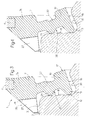
- sealing assembly 1 is assembled with lip 13 mating with a given amount of axial interference with sealing surface 8; lip 23 mates with sealing surface 8 with substantially no interference (i.e. with a small axial clearance) to permit fluid passage between sealing surface 8 and lip 23; and annular spur 27 is positioned facing and a small radial distance from lateral surface 31 of ring 3, so that annular sealing member 7 is positioned as a whole in a first operating position 7a ( Figure 3) wherein only lip 13 cooperates in fluidtight manner with sealing surface 8, while lip 23 permits fluid passage, in particular the passage of lubricating fluid, from cavity 35 towards lip 13.
- annular sealing member 7 is maintained substantially in operating position 7a as long as opposite annular faces 36, 37 of annular sealing member 7 are subjected to substantially equal pressures.
- annular spur 27 has, in known manner, a centrifugal effect inside cavity 35 on the lubricating fluid, which is thus at a predetermined pressure; and, at the same time, radial slits 28 enable lubricating fluid to flow towards, and so lubricate, lips 13, 23.
- the lubricating fluid flowing through radial slits 28, in fact, flows between lip 23 and sealing surface 8, which, mating with no interference, substantially define, in the above operating condition, a labyrinth seal (as opposed to a sliding seal), so that the lubricating fluid also flows towards, and lubricates, lip 13.
- annular sealing member 7 is elastically deformable to also assume, in use, a second operating position 7b ( Figure 4) when the pressure on annular face 36, facing sealing surface 8 and therefore also cavity 35 containing the lubricating fluid, is significantly less than the pressure on the opposite annular face 37.
- annular sealing member 7, in particular portions 10 and 11, is so deformed elastically as to also cause lip 23 to interfere with sealing surface 8, so that, in operating position 7b, lip 23 mates with a given amount of axial interference with, and so cooperates in sliding manner with, sealing surface 8.
- annular sealing member 7 is elastically deformable to selectively assume operating positions 7a and 7b according to the difference in the pressures on annular faces 36, 37. That is, in the event of a pressure difference over and above a predetermined value occurring in operating position 7a - wherein both annular faces 36, 37 are subjected to substantially the same pressure and only lip 13 cooperates in sliding manner with sealing surface 8 - annular sealing member 7 is deformed elastically so that lip 23 also cooperates in sliding manner with sealing surface 8. With both lips 13, 23 cooperating interferentially with sealing surface 8, sealing member 7 is thus better able to prevent the entry of contaminating substances between itself and sealing surface 8.
- the difference in the pressures on annular faces 36, 37 which causes lip 23 to cooperate interferentially with sealing surface 8 may be selected by appropriately sizing portions 10 and 11 of annular sealing member 7, and using appropriately deformable elastomers.
Landscapes
- Engineering & Computer Science (AREA)
- General Engineering & Computer Science (AREA)
- Mechanical Engineering (AREA)
- Rolling Contact Bearings (AREA)
- Sealing With Elastic Sealing Lips (AREA)
- Sealing Of Bearings (AREA)
- Mechanical Sealing (AREA)
Applications Claiming Priority (2)
| Application Number | Priority Date | Filing Date | Title |
|---|---|---|---|
| ITTO980904 | 1998-10-23 | ||
| IT1998TO000904A IT1305136B1 (it) | 1998-10-23 | 1998-10-23 | Complesso di tenuta per due organi meccanici accoppiati in rotazionerelativa, in particolare per due anelli di un cuscinetto a rotolamento |
Publications (3)
| Publication Number | Publication Date |
|---|---|
| EP0995917A2 true EP0995917A2 (de) | 2000-04-26 |
| EP0995917A3 EP0995917A3 (de) | 2000-11-22 |
| EP0995917B1 EP0995917B1 (de) | 2002-04-10 |
Family
ID=11417133
Family Applications (1)
| Application Number | Title | Priority Date | Filing Date |
|---|---|---|---|
| EP99120817A Expired - Lifetime EP0995917B1 (de) | 1998-10-23 | 1999-10-22 | Dichtungsanordnung für zwei verbundene, gegenseitig rotierende Teile, insbesondere für zwei Ringe eines Wälzlagers |
Country Status (7)
| Country | Link |
|---|---|
| US (1) | US6302403B1 (de) |
| EP (1) | EP0995917B1 (de) |
| JP (1) | JP4339467B2 (de) |
| AT (1) | ATE216034T1 (de) |
| DE (1) | DE69901217T2 (de) |
| ES (1) | ES2173694T3 (de) |
| IT (1) | IT1305136B1 (de) |
Cited By (1)
| Publication number | Priority date | Publication date | Assignee | Title |
|---|---|---|---|---|
| EP2093442A1 (de) * | 2006-11-14 | 2009-08-26 | NTN Corporation | Abgedichtetes wälzlager |
Families Citing this family (3)
| Publication number | Priority date | Publication date | Assignee | Title |
|---|---|---|---|---|
| JP4507368B2 (ja) * | 2000-08-25 | 2010-07-21 | 日本精工株式会社 | ボールねじ用シール、ボールねじ |
| DE102012219497A1 (de) * | 2012-10-25 | 2014-04-30 | Schaeffler Technologies Gmbh & Co. Kg | Dichtelement für ein Wälzlager |
| JP6532651B2 (ja) * | 2014-04-10 | 2019-06-19 | 日本精工株式会社 | シールリング付転がり軸受 |
Citations (5)
| Publication number | Priority date | Publication date | Assignee | Title |
|---|---|---|---|---|
| US2856208A (en) * | 1956-02-23 | 1958-10-14 | Gen Motors Corp | Closure |
| US3642335A (en) * | 1969-09-12 | 1972-02-15 | Nippon Seiko Kk | Sealed bearing |
| US4505484A (en) * | 1980-03-12 | 1985-03-19 | Nippon Seiko Kabushiki Kaisha | Sealing device for a rolling bearing |
| EP0198324A2 (de) * | 1985-04-19 | 1986-10-22 | RIV-SKF OFFICINE DI VILLAR PEROSA S.p.A | Dichtungseinheit mit doppeltem Dichtschild |
| EP0846900A1 (de) * | 1996-12-03 | 1998-06-10 | RFT S.p.A. | Wellenabdichtung, insbesondere für die Kühlwasserpumpe eines Kraftfahrzeuges |
Family Cites Families (3)
| Publication number | Priority date | Publication date | Assignee | Title |
|---|---|---|---|---|
| DE3607535A1 (de) * | 1986-03-07 | 1987-09-10 | Kugelfischer G Schaefer & Co | Abgedichtetes waelzlager |
| JP3740219B2 (ja) * | 1996-07-05 | 2006-02-01 | 光洋精工株式会社 | 転がり軸受の密封装置 |
| US5909880A (en) * | 1997-02-21 | 1999-06-08 | The Torrington Company | Polymer bearing seal and sealed bearing |
-
1998
- 1998-10-23 IT IT1998TO000904A patent/IT1305136B1/it active
-
1999
- 1999-10-22 DE DE69901217T patent/DE69901217T2/de not_active Expired - Lifetime
- 1999-10-22 ES ES99120817T patent/ES2173694T3/es not_active Expired - Lifetime
- 1999-10-22 AT AT99120817T patent/ATE216034T1/de not_active IP Right Cessation
- 1999-10-22 EP EP99120817A patent/EP0995917B1/de not_active Expired - Lifetime
- 1999-10-22 JP JP30113199A patent/JP4339467B2/ja not_active Expired - Lifetime
- 1999-10-25 US US09/425,964 patent/US6302403B1/en not_active Expired - Lifetime
Patent Citations (5)
| Publication number | Priority date | Publication date | Assignee | Title |
|---|---|---|---|---|
| US2856208A (en) * | 1956-02-23 | 1958-10-14 | Gen Motors Corp | Closure |
| US3642335A (en) * | 1969-09-12 | 1972-02-15 | Nippon Seiko Kk | Sealed bearing |
| US4505484A (en) * | 1980-03-12 | 1985-03-19 | Nippon Seiko Kabushiki Kaisha | Sealing device for a rolling bearing |
| EP0198324A2 (de) * | 1985-04-19 | 1986-10-22 | RIV-SKF OFFICINE DI VILLAR PEROSA S.p.A | Dichtungseinheit mit doppeltem Dichtschild |
| EP0846900A1 (de) * | 1996-12-03 | 1998-06-10 | RFT S.p.A. | Wellenabdichtung, insbesondere für die Kühlwasserpumpe eines Kraftfahrzeuges |
Cited By (2)
| Publication number | Priority date | Publication date | Assignee | Title |
|---|---|---|---|---|
| EP2093442A1 (de) * | 2006-11-14 | 2009-08-26 | NTN Corporation | Abgedichtetes wälzlager |
| EP2093442A4 (de) * | 2006-11-14 | 2012-12-05 | Ntn Toyo Bearing Co Ltd | Abgedichtetes wälzlager |
Also Published As
| Publication number | Publication date |
|---|---|
| JP2000170778A (ja) | 2000-06-20 |
| DE69901217T2 (de) | 2002-10-17 |
| US6302403B1 (en) | 2001-10-16 |
| EP0995917B1 (de) | 2002-04-10 |
| EP0995917A3 (de) | 2000-11-22 |
| ITTO980904A1 (it) | 2000-04-23 |
| ES2173694T3 (es) | 2002-10-16 |
| IT1305136B1 (it) | 2001-04-10 |
| JP4339467B2 (ja) | 2009-10-07 |
| ATE216034T1 (de) | 2002-04-15 |
| DE69901217D1 (de) | 2002-05-16 |
Similar Documents
| Publication | Publication Date | Title |
|---|---|---|
| US5511886A (en) | Bearing seal with oil deflectors | |
| US5522601A (en) | Locking labyrinth sealing assembly | |
| US4428586A (en) | Combination wear sleeve and excluder lip adapted for easy installation | |
| EP0508013B1 (de) | Dichtelemente für Lager | |
| AU2015204367B2 (en) | Low-friction dynamic seal | |
| US5967524A (en) | Hybrid seal device | |
| US6485022B1 (en) | Metallic labyrinth seal | |
| US3871666A (en) | Shaft packing | |
| US6386546B1 (en) | Seal cartridge | |
| EP0202702A1 (de) | Zentrifugale Abdichtung | |
| US6056293A (en) | Sealing assembly for a rotary shaft, in particular of an automotive engine water pump | |
| KR20070089141A (ko) | 밀봉장치 | |
| WO2013077010A1 (ja) | 密封装置 | |
| US5655781A (en) | Unitized radial and facial seal | |
| CN107461496B (zh) | 密封件及转动组件 | |
| US3762726A (en) | Fluid seal | |
| EP0995917B1 (de) | Dichtungsanordnung für zwei verbundene, gegenseitig rotierende Teile, insbesondere für zwei Ringe eines Wälzlagers | |
| CA1215417A (en) | Sealing assembly for a rolling bearing | |
| CA2074446C (en) | Cassette seal | |
| JP2809199B2 (ja) | ウォータポンプ用軸受シール装置 | |
| JPH0921397A (ja) | ウォータポンプ用軸受シール装置 | |
| US6612583B2 (en) | Bearing seal | |
| US4418920A (en) | Fluid seal for engine crankshaft applications | |
| JP2890355B2 (ja) | ウォータポンプ用軸受シール装置 | |
| JP2002139058A (ja) | ウォータポンプ装置 |
Legal Events
| Date | Code | Title | Description |
|---|---|---|---|
| PUAI | Public reference made under article 153(3) epc to a published international application that has entered the european phase |
Free format text: ORIGINAL CODE: 0009012 |
|
| AK | Designated contracting states |
Kind code of ref document: A2 Designated state(s): AT BE CH CY DE DK ES FI FR GB GR IE IT LI LU MC NL PT SE |
|
| AX | Request for extension of the european patent |
Free format text: AL;LT;LV;MK;RO;SI |
|
| PUAL | Search report despatched |
Free format text: ORIGINAL CODE: 0009013 |
|
| AK | Designated contracting states |
Kind code of ref document: A3 Designated state(s): AT BE CH CY DE DK ES FI FR GB GR IE IT LI LU MC NL PT SE |
|
| AX | Request for extension of the european patent |
Free format text: AL;LT;LV;MK;RO;SI |
|
| RIC1 | Information provided on ipc code assigned before grant |
Free format text: 7F 16C 33/78 A, 7F 16J 15/32 B |
|
| GRAG | Despatch of communication of intention to grant |
Free format text: ORIGINAL CODE: EPIDOS AGRA |
|
| 17P | Request for examination filed |
Effective date: 20010321 |
|
| 17Q | First examination report despatched |
Effective date: 20010606 |
|
| AKX | Designation fees paid |
Free format text: AT BE CH CY DE DK ES FI FR GB GR IE IT LI LU MC NL PT SE |
|
| GRAG | Despatch of communication of intention to grant |
Free format text: ORIGINAL CODE: EPIDOS AGRA |
|
| GRAH | Despatch of communication of intention to grant a patent |
Free format text: ORIGINAL CODE: EPIDOS IGRA |
|
| RAP1 | Party data changed (applicant data changed or rights of an application transferred) |
Owner name: SKF INDUSTRIE S.P.A. |
|
| REG | Reference to a national code |
Ref country code: GB Ref legal event code: IF02 |
|
| GRAH | Despatch of communication of intention to grant a patent |
Free format text: ORIGINAL CODE: EPIDOS IGRA |
|
| GRAA | (expected) grant |
Free format text: ORIGINAL CODE: 0009210 |
|
| AK | Designated contracting states |
Kind code of ref document: B1 Designated state(s): AT BE CH CY DE DK ES FI FR GB GR IE IT LI LU MC NL PT SE |
|
| PG25 | Lapsed in a contracting state [announced via postgrant information from national office to epo] |
Ref country code: NL Free format text: LAPSE BECAUSE OF FAILURE TO SUBMIT A TRANSLATION OF THE DESCRIPTION OR TO PAY THE FEE WITHIN THE PRESCRIBED TIME-LIMIT Effective date: 20020410 Ref country code: LI Free format text: LAPSE BECAUSE OF FAILURE TO SUBMIT A TRANSLATION OF THE DESCRIPTION OR TO PAY THE FEE WITHIN THE PRESCRIBED TIME-LIMIT Effective date: 20020410 Ref country code: IT Free format text: LAPSE BECAUSE OF FAILURE TO SUBMIT A TRANSLATION OF THE DESCRIPTION OR TO PAY THE FEE WITHIN THE PRE;WARNING: LAPSES OF ITALIAN PATENTS WITH EFFECTIVE DATE BEFORE 2007 MAY HAVE OCCURRED AT ANY TIME BEFORE 2007. THE CORRECT EFFECTIVE DATE MAY BE DIFFERENT FROM THE ONE RECORDED.SCRIBED TIME-LIMIT Effective date: 20020410 Ref country code: GR Free format text: LAPSE BECAUSE OF FAILURE TO SUBMIT A TRANSLATION OF THE DESCRIPTION OR TO PAY THE FEE WITHIN THE PRESCRIBED TIME-LIMIT Effective date: 20020410 Ref country code: FI Free format text: LAPSE BECAUSE OF FAILURE TO SUBMIT A TRANSLATION OF THE DESCRIPTION OR TO PAY THE FEE WITHIN THE PRESCRIBED TIME-LIMIT Effective date: 20020410 Ref country code: CH Free format text: LAPSE BECAUSE OF FAILURE TO SUBMIT A TRANSLATION OF THE DESCRIPTION OR TO PAY THE FEE WITHIN THE PRESCRIBED TIME-LIMIT Effective date: 20020410 Ref country code: BE Free format text: LAPSE BECAUSE OF FAILURE TO SUBMIT A TRANSLATION OF THE DESCRIPTION OR TO PAY THE FEE WITHIN THE PRESCRIBED TIME-LIMIT Effective date: 20020410 Ref country code: AT Free format text: LAPSE BECAUSE OF FAILURE TO SUBMIT A TRANSLATION OF THE DESCRIPTION OR TO PAY THE FEE WITHIN THE PRESCRIBED TIME-LIMIT Effective date: 20020410 |
|
| REF | Corresponds to: |
Ref document number: 216034 Country of ref document: AT Date of ref document: 20020415 Kind code of ref document: T |
|
| REG | Reference to a national code |
Ref country code: CH Ref legal event code: EP |
|
| REG | Reference to a national code |
Ref country code: IE Ref legal event code: FG4D |
|
| REF | Corresponds to: |
Ref document number: 69901217 Country of ref document: DE Date of ref document: 20020516 |
|
| PG25 | Lapsed in a contracting state [announced via postgrant information from national office to epo] |
Ref country code: SE Free format text: LAPSE BECAUSE OF FAILURE TO SUBMIT A TRANSLATION OF THE DESCRIPTION OR TO PAY THE FEE WITHIN THE PRESCRIBED TIME-LIMIT Effective date: 20020710 Ref country code: PT Free format text: LAPSE BECAUSE OF FAILURE TO SUBMIT A TRANSLATION OF THE DESCRIPTION OR TO PAY THE FEE WITHIN THE PRESCRIBED TIME-LIMIT Effective date: 20020710 Ref country code: DK Free format text: LAPSE BECAUSE OF FAILURE TO SUBMIT A TRANSLATION OF THE DESCRIPTION OR TO PAY THE FEE WITHIN THE PRESCRIBED TIME-LIMIT Effective date: 20020710 |
|
| ET | Fr: translation filed | ||
| NLV1 | Nl: lapsed or annulled due to failure to fulfill the requirements of art. 29p and 29m of the patents act | ||
| REG | Reference to a national code |
Ref country code: CH Ref legal event code: PL |
|
| REG | Reference to a national code |
Ref country code: ES Ref legal event code: FG2A Ref document number: 2173694 Country of ref document: ES Kind code of ref document: T3 |
|
| PG25 | Lapsed in a contracting state [announced via postgrant information from national office to epo] |
Ref country code: LU Free format text: LAPSE BECAUSE OF NON-PAYMENT OF DUE FEES Effective date: 20021022 Ref country code: IE Free format text: LAPSE BECAUSE OF NON-PAYMENT OF DUE FEES Effective date: 20021022 |
|
| PG25 | Lapsed in a contracting state [announced via postgrant information from national office to epo] |
Ref country code: ES Free format text: LAPSE BECAUSE OF NON-PAYMENT OF DUE FEES Effective date: 20021023 |
|
| PG25 | Lapsed in a contracting state [announced via postgrant information from national office to epo] |
Ref country code: CY Free format text: LAPSE BECAUSE OF FAILURE TO SUBMIT A TRANSLATION OF THE DESCRIPTION OR TO PAY THE FEE WITHIN THE PRESCRIBED TIME-LIMIT Effective date: 20021031 |
|
| PLBE | No opposition filed within time limit |
Free format text: ORIGINAL CODE: 0009261 |
|
| STAA | Information on the status of an ep patent application or granted ep patent |
Free format text: STATUS: NO OPPOSITION FILED WITHIN TIME LIMIT |
|
| 26N | No opposition filed |
Effective date: 20030113 |
|
| PG25 | Lapsed in a contracting state [announced via postgrant information from national office to epo] |
Ref country code: MC Free format text: LAPSE BECAUSE OF NON-PAYMENT OF DUE FEES Effective date: 20030501 |
|
| REG | Reference to a national code |
Ref country code: IE Ref legal event code: MM4A |
|
| REG | Reference to a national code |
Ref country code: ES Ref legal event code: FD2A Effective date: 20031112 |
|
| REG | Reference to a national code |
Ref country code: FR Ref legal event code: PLFP Year of fee payment: 17 |
|
| REG | Reference to a national code |
Ref country code: DE Ref legal event code: R082 Ref document number: 69901217 Country of ref document: DE Representative=s name: PATENTANWAELTE OLBRICHT, BUCHHOLD, KEULERTZ PA, DE |
|
| REG | Reference to a national code |
Ref country code: FR Ref legal event code: PLFP Year of fee payment: 18 |
|
| REG | Reference to a national code |
Ref country code: FR Ref legal event code: PLFP Year of fee payment: 19 |
|
| REG | Reference to a national code |
Ref country code: FR Ref legal event code: PLFP Year of fee payment: 20 |
|
| PGFP | Annual fee paid to national office [announced via postgrant information from national office to epo] |
Ref country code: FR Payment date: 20181030 Year of fee payment: 20 Ref country code: GB Payment date: 20181031 Year of fee payment: 20 |
|
| PGFP | Annual fee paid to national office [announced via postgrant information from national office to epo] |
Ref country code: DE Payment date: 20181228 Year of fee payment: 20 |
|
| REG | Reference to a national code |
Ref country code: DE Ref legal event code: R071 Ref document number: 69901217 Country of ref document: DE |
|
| REG | Reference to a national code |
Ref country code: GB Ref legal event code: PE20 Expiry date: 20191021 |
|
| PG25 | Lapsed in a contracting state [announced via postgrant information from national office to epo] |
Ref country code: GB Free format text: LAPSE BECAUSE OF EXPIRATION OF PROTECTION Effective date: 20191021 |