FIELD OF THE INVENTION
-
This invention relates to slide gate mechanisms for use in the casting of molten
metal. In particular, the present invention describes an article for securely, yet
removably, mounting a refractory plate into such a mechanism.
DESCRIPTION OF THE PRIOR ART
-
In the casting of molten metal, a slide gate mechanism is commonly employed to
control flow of the molten metal from a bottom orifice of a metallurgical vessel. A slide
gate mechanism comprises at least two plates and a supporting frame for each plate.
Each plate fits inside a plate location of a supporting frame. The supporting frames
compressively engage the sliding surfaces of the plates and permit the plates to slide
across one another. Each plate contains at least one throughbore opening that, when
aligned with a throughbore opening on the other plate, permits flow of the molten metal.
-
A plate comprises a refractory plate and a metal sheath for securing the plate in
the supporting frame. The metal sheath may be a can or band. A can will cover at least
parts of the peripheral edge of the refractory plate and the non-sliding surface. The plate
is typically secured in the can with mortar. The metal sheath may also be a band that
circumscribes the peripheral edge of the refractory plate. The band may optionally be
placed in tension to exert a compressive force on the refractory plate. Tension creates a
compressive force on the plate thereby reducing crack opening and crack propagation.
Tension is accomplished by a tightening means. One tightening means is hot banding,
which places a heated band around the refractory. As the band cools, it shrinks to
create a compressive force around the plate. The band may also be a split ring. The split
ring may be a single piece or multiple pieces that may be spread to fit around the
peripheral edge of the refractory plate before tightening. The tightening means will then
comprise bolts, springs, clamps or other mechanical fasteners. The band may also, for
example, be wrapped around the plate and welded in place.
-
A two-plate slide gate mechanism comprises a top plate and a bottom plate. The
top plate is typically fixed in place and attached to an inner nozzle. The inner nozzle is
fixedly secured within the bottom orifice but may protrude beyond the bottom orifice of
the vessel. The bottom plate is movable and attached to a collector nozzle. Both top and
bottom plates are typically fixedly attached to their respective nozzles by, for example,
mortar.
-
While the plates may move relative to each other, they should not move relative
to the nozzle to which they are attached. Movement may destroy the attachment of the
plate to the nozzle and open an interface between the two pieces. Molten metal may
then issue from such an opening and catastrophically affect the function of the slide gate
and the casting of the metal. Consequently, the supporting frame typically prevents the
plate from moving relative to the nozzle.
-
Although secured within the supporting frame, the plates must also be easily
removable as wear and the corrosive and erosive effects of molten metal require the
plates to be replaced periodically. A number of clamping means are used to securely, yet
removably, mount a refractory plate into a slide gate mechanism while maintaining
positive attachment of the plate to the nozzle. For example, the plate and nozzle may
have a boss and complimentary indentation to lock the two pieces together. The
presence of a boss or indentation on the non-sliding surface of the plate necessarily
creates a plate that has only one sliding surface. Additionally, the boss is a ceramic and
may crack under the stresses imposed by the slide gate mechanism.
-
A common technique to secure a plate involves clamping the plate within the
supporting frame by immobilizing the plate with one or more screws, bolts, eccentric
fasteners or other mechanical fasteners. The use of such fasteners requires an
additional operation when clamping the plate in the supporting frame. Such fasteners
can also create high stress concentrations and lead to fracture of the refractory plate.
Certain metal sheathing can reduce stress concentrations. A rigid, metal can, for
example, is able to diffuse stresses over a broad area, and the elasticity of the mortar
may further reduce stresses transmitted to the plate. Stress concentrations may be
greater in banded plates because a band is typically less rigid than a can and no mortar
is present between the band and the refractory plate. Slits or recesses in the refractory
plate beneath the metal band and at the point of loading have been used to reduce such
stress concentrations. Metal sheathing does not completely eliminate stress
concentrations and still requires an additional operation to secure the plate in the
supporting frame.
-
Protrusions or indentations have been included on a plate's non-sliding surface
to reduce the number of mechanical operations necessary to clamp the plate in the
frame. The protrusions and indentations act to lock the plate in place by cooperating
with corresponding features in the supporting frame. The protrusions and indentations
are not coplanar with the sliding surface and, therefore, create torsional forces on the
refractory plate. Such forces can create unacceptable stress concentrations, which may
fracture or distort the can or plate.
-
Thermal expansion disparities between the refractory plate, metal sheath and
supporting frame also produces stress concentrations in the plate. For example, a plate
at around room temperature may be clamped in a supporting frame, which is at
relatively high temperature. As the plate approaches operating temperatures, it expands
against the clamping means to generate stresses that could crack, warp or destroy the
plate or supporting frame.
-
Prior art attempts to securely, yet removably, mount a plate in a supporting frame
of a slide gate mechanism have several deficiencies. Multiple mechanical operations can
be involved in securing the plate in the mechanism. Mechanical clamps, such as screws
or bolts, typically involve point loading, which create stress concentrations. Cracking
and fracture of the refractory plates may follow. Thermal expansion may also generate
stresses between the plate and the metal supporting frame. A metal sheath may reduce
stresses on the refractory plate but has not eliminated fracture caused by the clamping
means. A need persists for a plate, which may be reliably and removably secured in a
slide gate mechanism without additional operations or concentrating mechanical or
thermal stresses in the plate.
SUMMARY OF THE INVENTION
-
The present invention describes a self-clamping plate for use in a slide gate
mechanism. One object of the invention is to secure a plate in a supporting frame of a
slide gate mechanism without the need to perform additional mechanical operations. A
second object of the invention is to reduce stress concentrations and torsional forces in
a refractory plate secured in a supporting frame.
-
One aspect of the invention describes a refractory plate circumscribed by a metal
sheath that may be secured to a supporting frame of a slide gate mechanism by at least
two lugs cooperatively engaging corresponding indentations. The lugs may be either on
the plate or the frame. At least one lug will be on either side of an axis defined by the
direction of the plate's motion when the plate is in the slide gate mechanism.
-
Another aspect of the invention teaches having the lugs near the centerline of the
plate's throughbore opening. Still another aspect of the invention discloses at least one
lug designed to prevent misinsertion of the plate in the slide gate mechanism. Such a
lug may be positioned or vary in shape to prevent misinsertion.
-
One embodiment of the metal sheath is described as a metal can into which the
plate is fixedly secured. Alternatively, the invention describes the metal sheath as a
metal band. The metal band may be a continuous band or a split ring secured to the
refractory plate with a tightening means.
-
An alternative embodiment of the invention describes a plate having a refractory
plate with a chamfered edge. The metal sheath is a clamping ring having an inner
chamfered edge cooperatively engaging the chamfered edge of the refractory plate. The
clamping ring also has an outer peripheral edge that may be secured in a plate location
of a supporting frame by at least two lugs cooperatively engaging corresponding
indentations. The lugs may be either on the supporting frame or the clamping ring. A
mounting means is adapted to secure the clamping ring in the plate location so that the
clamping ring may move freely perpendicular to the working face. The mounting means
also urges the chamfered inner edge of the clamping ring against the chamfered edge of
the refractory plate, so that as the metal and ceramic expand and contract, good contact
will be maintained between the clamping ring and the plate.
-
One aspect of the alternative embodiment describes the mounting means as
comprising a plurality of bolts loosely connecting the clamping ring and the supporting
frame, and a plurality of springs between the frame and the clamping ring that urge the
clamping ring against the refractory plate.
BRIEF DESCRIPTION OF THE DRAWINGS
-
FIG. 1 shows a prior art metal-sheathed refractory plate secured to the slide gate
mechanism with eccentric fasteners.
-
FIG. 2 shows a metal-sheathed refractory plate of the present invention having
lugs on the outside surface of a metal band which lugs engage indentations in the slide
gate mechanism.
-
FIG. 3 shows a metal-sheathed refractory plate of the present invention having
lugs shaped and located to prevent misinsertion of the plate in the slide gate
mechanism.
-
FIG. 4 shows a refractory plate circumscribed by a two-piece, split ring metal
band tightened against the peripheral edge of the plate with a pair of bolts.
-
FIG. 4A shows a non-planar interface between the metal sheath and the
peripheral edge of the refractory plate.
-
FIG. 5 shows a refractory plate having a chamfered peripheral edge fitting into a
clamp ring having the inverse chamfer. Springs urge the clamp ring against the plate
and lugs on the clamp ring secure the plate in the slide gate mechanism.
-
FIG. 6 is a cross-sectional view of Fig. 5 along the A-A plane showing the plate,
clamping ring, bolts holding the ring in place and springs urging the chamfered edge of
the clamping ring against the corresponding chamfered edge of the plate.
DESCRIPTION OF THE PREFERRED EMBODIMENTS
-
As shown in FIG. 1, prior art commonly secures a refractory plate 1 to a
supporting frame 5 by clamping the refractory plate 1 into a plate location 10 of the
frame 5. Clamping may involve an eccentric fastener 11 impinging on a metal sheath 2
surrounding the peripheral edge 1A of the refractory plate 1. Pressure from the
fasteners 11 may create stress concentrations within the refractory plate 1 leading to
fracture.
-
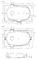
One embodiment of the article of the present invention is shown in FIG. 2. A
metal sheath 2 circumscribes at least part of the peripheral edge 1A of a refractory plate
1, which also has at least one throughbore opening 20 to permit the passage of molten
metal. The throughbore opening 20 has a centerline 21 perpendicular to the axis of
motion 6 of the plate 1. The metal sheath 2 is shown seated at a plate location 10 in a
supporting frame 5 of a slide gate mechanism (not shown). It is to be distinctly
understood that whenever reference is made to a plate location in a slide gate
mechanism, the presence of a supporting frame is implied.
-
A space 9 should be present to accommodate thermal expansion of the metal
sheath 2 and refractory plate 1. At least two lugs 3 are present to secure the outer
peripheral edge 2A of the metal sheath 2 to the supporting frame 5. The lugs 3 are
adapted to fit into indentations 4. It should be appreciated that the lugs 3 could be on
the supporting frame 5 or the outer peripheral edge 2A of the metal sheath 2 with the
indentations 4 in the metal sheath 2 or frame 5, respectively. For clarity and simplicity,
any reference to a lug on the metal sheath will subsume the alternative embodiment
with the lug on the frame. This includes various combinations of lugs and indentations
including, for example, where at least one lug and at least one indentation are each on
the plate.
-
Placement of the lugs along the outer peripheral edge of the plate permits the
lugs to be placed near the sliding surface of the plate. Prior art has described
protrusions on the non-sliding surface of the plate that are inherently distant from the
sliding surface. Torsional stresses increase proportionally to the distance of a protrusion
from the sliding surface. Therefore, lugs on the outer peripheral edge will generate lower
torsional stresses than protrusions on the non-sliding surface. In the present invention,
the lugs will preferably be near the sliding surface.
-
Lugs should fit in the indentations with a mechanical tolerance between 0.1 mm
and 1 mm, preferably 0.1 mm to 0.5 mm. The lugs 3 should be located on each side of
the axis of motion 6. Movement of the frame 5 will cause the lugs 3 to contact faces 7 in
the indentation 4 thereby moving the metal sheath 2 and refractory plate 1. The metal
sheath 2 around the peripheral edge 1A of the refractory plate 1 disperses the stresses
generated by this contact. Stress concentrations at any single point in the refractory
plate 1 are thereby reduced.
-
Lugs may be created by a number of processes. Lugs may be formed from
or welded onto the metal sheath. Lugs may also be attached using adhesive or
mechanical fasteners. Lugs may be machined from the metal sheath or formed by
bending, stamping or pressing. Lugs may even be positioned or machined after the
metal sheath is fixed on the refractory plate. Obviously, numerous methods of forming
lugs may be employed so long as the completed lug is operable.
-
Lugs have width, length and height dimensions. Length refers to the dimension
parallel to the peripheral edge and along the axis of motion. Width refers to the
dimension perpendicular to the peripheral edge and axis of motion, that is, the distance
a lug projects from the sheath's outer peripheral edge. Height refers to the remaining
orthogonal axis dimension, that is, along the thickness of the plate.
-
Lugs should be large enough to provide the mechanical strength necessary to
move the refractory plate but small enough that differential thermal expansion between
the lugs and the indentations does not impair a strong mechanical connection. Larger
lugs will be less likely to detach from the metal sheath and will also be stronger and less
subject to mechanical stresses. However, larger lugs will thermally expand a greater
amount and decrease the fit at any temperature. Additionally, wider lugs tend to induce
a greater torsional stress on the plate force because such stress is roughly proportional
to the width of the lug.
-
To satisfy these competing criteria, a lug should be between 50 and 150,
preferably about 80 to 120, millimeters long, and between 1 and 10, preferably about 4
to 6, millimeters wide. The height of the lug will typically be at least one-half the
thickness of the plate. Preferably, the lug is at least two-thirds the thickness of the
plate.
-
Lugs should extend perpendicular to the motion of the plate. With reference to
FIG. 2, lugs 3 perpendicular to the axis of motion 6 engage the supporting frame 5
through contact faces 7, thereby moving the plate 1. The lugs 3 should be positioned to
minimize torsional forces on the plate 1. Lugs 3 will preferably be on both sides of the
axis of motion 6. Lugs near the centerline 21 of the plate's throughbore opening 20 may
reduce misalignment of the plate and the nozzle caused by thermal variation, thereby
reducing the chance of joint fracture. Near in this case is defined as within 100 mm of
the centerline 21. Lugs away from the centerline may reduce the working temperature
of the lugs during pouring and improve mechanical tolerances. In a preferred
embodiment, two lugs 3 on opposite sides of the axis of motion 6 will be at the
centerline 21 of the plate's throughbore opening 20.
-
The placement and dimensions of the lugs can be varied to prevent misinsertion
of the plate. For example, asymmetrical placement of the lugs will prevent the plate from
being inserted improperly. Varying the length or the width of the lugs will also prevent
misinsertion. FIG. 3 shows a metal sheath 2 having a first lug 3A cooperating with a
first indentation 4A. A second lug 3B is located along the metal sheath 2 asymmetrically
from the first lug 3A and, in this example, the second lug 3B is also differently shaped
from the first lug 3A. The second lug 3B cooperates with a second indentation 4B. The
different placement and shape of the lugs prevent misinsertion.
-
The plate's metal sheath may comprise a metal can or band. When using a metal
can, a refractory plate is typically mortared into the can so that the peripheral edge and
at least part of the non-sliding surface is metal-sheathed. On the non-sliding surface,
the metal can may also have protrusions to align the plate within the mechanism.
Instead of a metal can, a metal band, which is mechanically secured to the plate, may
also be used. Physical dimensions of the sheath are dictated by the need for the sheath
to handle stresses transmitted through the lugs. The sheath may cover the entire
peripheral edge of the refractory plate. Preferably, the sheath covers at least one-half the
thickness of the plate. The thickness of the metal comprising the sheath should be at
least about 3 mm for strength. Preferably, the sheath is about 5-10 mm thick.
-
A metal band may be secured to the plate by a number of known tightening
means. A tightening means is any sort of procedure or fastener intended to secure the
band around the plate, and may include, for example, hot banding, welding, adhesives,
and mechanical fasteners such as clamps, bolts, rivets and the like. Particularly useful
are mechanical fasteners that permit removal of the metal band from the plate. The
metal band may comprise a single piece or multiple pieces. Commonly, the band is an
unbroken, continuous band secured by hot banding or welding. The band may also be a
split ring. A split ring means any discontinuous ring comprising either one or more
pieces. A split ring may be easily fitted around the plate and can later be secured to the
plate by a tightening means. For example, FIG. 4 shows a metal band comprising a first
piece 2A and a second piece 2B. The pieces are tightened around the refractory plate 1
by a pair of bolts 11 that draw the two pieces together and secure the pieces around the
peripheral edge 1A of the refractory plate 1. When the plate is spent, the bolts 11 may
be loosened and the refractory plate 1 removed from the metal band 2. The metal band
2 may be reused and a new refractory plate may be clamped in the metal band. As
shown in FIG. 4A, the metal band 2 and peripheral edge 1A may have a non-linear
interface 12. Such an interface 12 may be grooved or notched to secure the plate 1 to
the metal band 2.
-
The metal sheath, as either a can or band, may be made from more than one
layer of metal. It is known that the heat transfer coefficient perpendicular to a layer of
metal is lower than parallel to the same layer. Layers of metal within the metal sheath
parallel to the height of the refractory plate and perpendicular to the width of the lug can
decrease heat transfer through the sheath. Lower heat transfer may result in lower
operating temperatures for the lugs and, consequently, lower thermally induced
mechanical stresses.
-
An alternative embodiment of the present invention is shown in Figs. 5 and 6. A
metal band is present as a clamping ring 2 having a working face 25 and an inner
chamfered edge 14, which preferably has an angle perpendicular to the working face 25
of between about ten (10) and twenty (20) degrees. The refractory plate 1 is thicker than
the clamping ring 2 and has a peripheral edge 1A chamfered to mate with the inner edge
14 of the clamping ring 2. A mounting means secures the clamping ring 2 to a plate
location 10 in a supporting frame 5 of the slide gate mechanism (not shown) so that in
operation the clamping ring 2 is urged against the plate 1 and can move only
perpendicular to the working surface 2A. As the plate 1 and the clamping ring 2
expand, the clamping ring 2 slides along the chamfered edge to remain in alignment
with the plate 1.
-
FIG. 6 shows a mounting means comprising bolts 21 and springs 22, which
continuously urge together the chamfered edges of the plate 1A and the clamping ring
14. Not shown is a second refractory plate that would compressively engage the plate 1
while the slide gate is in operation. This arrangement permits a secure contact between
the plate 1 and the clamping ring 2 regardless of the dissimilar thermal expansion or
contraction of the plate 1, ring 2 or mechanism 5. Contact around the entire peripheral
edge 1A of the plate 1 is expected to reduce stress concentrations in the plate 1. Such
contact may also impart a crack-closing pre-load on the plate.
-
The mounting means can be any arrangement of mechanical elements that
secures the clamping plate to the slide gate mechanism and urges the clamping plate
against the plate. Obvious variations include bolts, rivet or dowels in combination with
any elastic material or spring that would push the clamping ring against the plate.
-
Obviously, numerous modifications and variations of the present invention are
possible. It is, therefore, to be understood that within the scope of the following claims,
the invention may be practiced otherwise than as specifically described.