EP0995512A2 - Method and device for sealing a hollow profile or similar workpiece in high pressure forming - Google Patents
Method and device for sealing a hollow profile or similar workpiece in high pressure forming Download PDFInfo
- Publication number
- EP0995512A2 EP0995512A2 EP99810889A EP99810889A EP0995512A2 EP 0995512 A2 EP0995512 A2 EP 0995512A2 EP 99810889 A EP99810889 A EP 99810889A EP 99810889 A EP99810889 A EP 99810889A EP 0995512 A2 EP0995512 A2 EP 0995512A2
- Authority
- EP
- European Patent Office
- Prior art keywords
- stamp
- space
- sealing element
- profile
- active medium
- Prior art date
- Legal status (The legal status is an assumption and is not a legal conclusion. Google has not performed a legal analysis and makes no representation as to the accuracy of the status listed.)
- Granted
Links
Images


Classifications
-
- B—PERFORMING OPERATIONS; TRANSPORTING
- B21—MECHANICAL METAL-WORKING WITHOUT ESSENTIALLY REMOVING MATERIAL; PUNCHING METAL
- B21D—WORKING OR PROCESSING OF SHEET METAL OR METAL TUBES, RODS OR PROFILES WITHOUT ESSENTIALLY REMOVING MATERIAL; PUNCHING METAL
- B21D26/00—Shaping without cutting otherwise than using rigid devices or tools or yieldable or resilient pads, i.e. applying fluid pressure or magnetic forces
- B21D26/02—Shaping without cutting otherwise than using rigid devices or tools or yieldable or resilient pads, i.e. applying fluid pressure or magnetic forces by applying fluid pressure
- B21D26/033—Deforming tubular bodies
- B21D26/045—Closing or sealing means
Definitions
- the invention relates to a method and an apparatus for forming a hollow profile or the like.
- Workpiece by means of an internal high pressure generated by a flowable active medium in the sealed profile space of the hollow profile, whereby at least one sealing element from the active medium a receiving space of a stamp-like tool part is guided radially outwards.
- DE 35 32 499 C1 describes a device for hydraulic Widening a pipe section by means of a Tube insertable cone-like cylindrical probe that by means of at least two spaced apart Sealing rings with the pipe section to be expanded Annulus forms, which is filled with pressure medium to expand becomes; the two sealing rings are each in an annular shape Receiving groove U-shaped cross section arranged in the probe and have in the initial state when the Probe into the tube at most the outside diameter of the Corresponding outer diameter. Before the expansion process begins they are used to seal the annular gap radial pressure between the probe and the pipe, the grooves through a to the pressure medium supply connected connecting line supplied becomes.
- the pressure medium supply to the annulus occurs exclusively over at least one of the grooves and will controlled by a sealing ring serving as a valve body, the opening between the receiving groove and the annular space closes until it expands due to elastic expansion has achieved its sealing effect. That groove is in its edge adjacent to the annulus with at least one bevelled incision. If the pressure in the Annulus between the two seals increases the pipe wall widen in this area.
- the profile space covering tool part added and the sealing element to one between the hollow profile and the one attached to it stamp-like tool part created. It can the active medium from the space for the sealing element in the Profile space can be initiated.
- an insert between serves here Pressure line mouth and sealing element as an additional Wear protection. This deposit must consist of one wear-resistant material and can be loose or with the Sealing element to be firmly connected.
- the sealing element can axially and / or radially biased.
- stamp-like tool part a radial shoulder surface as a stop for a front edge of the designed as a single or multi-chamber profile has and on the circumference of an insertable in the profile space
- at least one annular groove for the sealing element is provided, which is to the longitudinal axis of the stamp towards at least one feed space for the active medium spanned and can be lifted off from the feed space by this;
- the stamp heel that can be inserted into the profile space is on the radially protruding shoulder surface added, which with a joint between the abutting front edge of the hollow profile limited to which this was designed as a sealing ring Allows the sealing element to be applied through the active medium.
- the Ring or sealing groove another groove as a feed space for the active medium by at least one in the stamp add running channel to a source for the active medium is; if necessary, the further groove is an inner groove molded into the deepest of the ring or sealing groove and the latter is assigned radially.
- the annular groove is as Shoulder groove shaped with an undercut Cross-sectional part and one as an open contact surface for the Sealing element trained section, above all when the stamp paragraph is a separate part of the approach Stamp is.
- the annular sealing element is therefore on a Paragraph or shoulder of the stamp in the ring groove that extend also axially parallel over that shoulder surface can.
- the active medium flows into the Inner groove under the sealing element and expands it, until it lies in front of that joint. Now flows in one configuration the active medium over the inner edge of the ring or Sealing groove - or through holes - in the workpiece on.
- the holes can be arranged or the inside edge can be designed so that the active medium only in the Workpiece or the profile space flows when the sealing element the joint lies at these critical points.
- sealing ring a band-like inner section with about this in Rib shaped center of cross section.
- Rib shaped center of cross section By this stipulation a cross section is created that corresponds to that of a hat.
- the central rib of this sealing ring is in Installation position on the one hand from a section of the stamp approach and on the other hand from an annular rib of the head part flanked.
- the elastic seal adapts during calibration the changing shape of the hollow profile during the forming or the workpiece. Will the pressure in the workpiece again dismantled, the seal returns to its original position; The stamp and seal can be smoothly removed from the Workpiece are extended.
- the end edge 14 of the hollow profile 10 has to strike the stamp 16 in a sealed manner.
- the stamp 16 is provided with a radial shoulder surface 18 of an outer diameter d, to which a cylindrical stamp extension 20 of a smaller diameter d 1 is connected.
- the height of the circumferential surface 22 of the cylindrical stamp shoulder 20 parallel to the longitudinal axis A of the stamp 16 is denoted by h in FIG. 1.
- annular groove 24 in the peripheral surface 22 thereof molded to accommodate a sealing ring 26.
- the annular groove 24 molded and the cross section of the Annular groove 24 of width b stepped inner groove 25 on both sides smaller width e. Go from this - in the illustrated Embodiment six - radial channels 28, the other at 29 in a central recess 30 of the stamp 16 mouth.
- the cross section of this cylindrical in itself Recess 30 tapers near the inside of the stamp or stamp face 17 in an area 32 to be conical an axial or outflow channel 34.
- an axial channel 34 usable pressure valve which in the embodiment of FIG. 3rd is indicated at 38. This is set so that it opens at the pressure under which the sealing ring 26 of the sealing edge abuts, and so the inlet of a larger volume flow or the lower loss inlet of the Active medium in the profile space 12 allows.
- the Sealing ring 26 made of elastic material 26 which is changing Shape of the hollow profile 10. In this the Relieved of pressure, the sealing ring 26 goes into its initial position back into the ring groove 24 so that the sealing ring 26 with the stamp 16 again smoothly out of the profile space 12 can be extended.
- a sealing ring 40 is inserted which has a band-like inner section 41, from the cross-sectional center of which a rib 44 chamfered at its edges 42 is formed; a narrow edge region of the inner portion 41 of the sealing ring 40 is inserted on the one hand into the undercut part of the shoulder groove 24 a and on the other hand overlapped by an axial ring rib 46 of the head part 19.
- the installation or attachment of the schematically illustrated throttle valve 38 ensures that when the pressure in the profile 10 builds up, pressure is first generated on the sealing ring 40 before the internal pressure is built up in the profile 10; the response of the seal is guaranteed.
- Fig. 5 also shows a two-part stamp 16 b from a head part 19 b and a separate cylindrical stamp extension 20 b , which is inserted into an insert space 48 of the head part 19 b .
- the annular groove 24 of rectangular cross section receives the correspondingly designed sealing ring 26, which is partially covered by the side surface 49 of an annular edge 50 surrounding the insert space 48; the latter offers that shoulder surface 18.
- the shape of the stamp 16 c corresponds approximately to that of the stamp 16 of FIG. 2, but the sealing ring 26 c rests on the peripheral surface 22, which is formed by an annular groove 24 c formed in the shoulder surface 18 parallel to the axis via the shoulder surface 18 is extended.
- the sealing ring 26 c at the other end has a shoulder indentation 52 arranged on its outer edge, into which an edge rib 54 of a stamp cover 56 engages. The latter is screwed at 58 to the cylindrical stamp approach 20 c .
- FIG. 7 shows a stamp 16 d with an axially continuous filling line 60 for the hollow profile 10 and a separate eccentric pressure line 62, which connects to the inner groove 25 with a radial section 64; this pressure line 62/64 is used to control the sealing ring 40 a .
- an impact or wear insert made of metal or the like. Wear-resistant material is designated, which is provided in front of the mouth of a radial section 64 on the inner groove 25.
Landscapes
- Physics & Mathematics (AREA)
- Fluid Mechanics (AREA)
- Engineering & Computer Science (AREA)
- Mechanical Engineering (AREA)
- Sealing Devices (AREA)
- Shaping Metal By Deep-Drawing, Or The Like (AREA)
- Gasket Seals (AREA)
- Casting Or Compression Moulding Of Plastics Or The Like (AREA)
Abstract
Description
Die Erfindung betrifft ein Verfahren sowie eine Vorrichtung zum Umformen eines Hohlprofils od.dgl. Werkstückes mittels eines durch ein strömbares Wirkmedium erzeugten Innenhochdrucks im abgedichteten Profilraum des Hohlprofils, wobei wenigstens ein Dichtungselement durch das Wirkmedium aus einem es aufnehmenden Raum eines stempelartigen Werkzeugteils radial nach außen geführt wird.The invention relates to a method and an apparatus for forming a hollow profile or the like. Workpiece by means of an internal high pressure generated by a flowable active medium in the sealed profile space of the hollow profile, whereby at least one sealing element from the active medium a receiving space of a stamp-like tool part is guided radially outwards.
Beim sog. Innenhochdruck-Umformen (IHU-Verfahren) wird das Hohlprofil durch Innendruck ausgedehnt. Zusätzlich kann das Hohlprofil mittels wenigstens eines Stempels nachgeschoben werden, der am Werkstück stirnseitig angreift. Letzteres kann so aufgeweitet, gestaucht bzw. expandiert werden.With so-called hydroforming (IHU process), this becomes Hollow profile expanded by internal pressure. In addition, that can Hollow profile pushed by means of at least one stamp that attacks the workpiece on the front. The latter can be expanded, compressed or expanded in this way.
Bei einem Doppel- oder Mehrkammerprofil dehnen sich dessen Stege zwischen den einzelnen Kammern anders aus als die übrigen Wandungen. Scharfe Ecken oder plötzliche Wanddickenänderungen im Werkstück führen zudem zu ungleichmäßiger Verformung beim Kalibrieren.With a double or multi-chamber profile, the stretch Bridge between the individual chambers differently than the others Walls. Sharp corners or sudden changes in wall thickness in the workpiece also lead to more uneven Deformation when calibrating.
Es ist bekannt, die Stirnseiten des Hohlprofils abzudichten, um in diesem den Hochdruck zu halten. Bisherige Dichtverfahren bedienen sich konisch geformter PUR- oder Stahldichtstempel, die in das Hohlprofil eingefahren werden. Sie vermögen die ungleichmäßige Verformung nicht auszugleichen und verschleißen schnell durch die beim Einfahren in das Hohlprofil auftretende Reibung. Weicht die Form des Profils zu stark von den Sollwerten ab, muss die Dichtung noch weiter einfahren, was den Verschleiß erhöht; andernfalls kann sie gar nicht mehr abdichten.It is known to seal the end faces of the hollow profile, to keep the high pressure in this. Previous sealing processes use conically shaped PUR or steel seals, which are inserted into the hollow profile. she cannot compensate for the uneven deformation and wear out quickly when entering the Hollow profile friction. Deviates the shape of the profile If the seal deviates too much from the setpoints, run in, which increases wear; otherwise can no longer seal them.
Die DE 35 32 499 C1 beschreibt eine Vorrichtung zum hydraulischen Aufweiten eines Rohrabschnitts mittels einer in das Rohr einführbaren zapfenartigen zylindrischen Sonde, die mittels mindestens zweier im Abstand voneinander befindlicher Dichtringe mit dem aufzuweitenden Rohrabschnitt einen Ringraum bildet, der zum Aufweiten mit Druckmittel gefüllt wird; die beiden Dichtringe sind jeweils in einer ringförmigen Aufnahmenut U-förmigen Querschnitts in der Sonde angeordnet und haben im Ausgangszustand beim Einführen der Sonde in das Rohr einen höchstens dem Außendurchmesser der Sonde entsprechenden Außendurchmesser. Vor Beginn des Aufweitungsvorganges werden sie zur Abdichtung des Ringspaltes zwischen Sonde und Rohr radial mit Druckmittel beaufschlagt, das den Aufnahmenuten durch eine an die Druckmittelzuführung angeschlossene Verbindungsleitung zugeführt wird. Die Druckmittelzufuhr zum Ringraum geschieht ausschließlich über zumindest eine der Aufnahmenuten und wird durch einen als Ventilkörper dienenden Dichtring gesteuert, der eine zwischen Aufnahmenut und Ringraum befindliche Öffnung so lange verschließt, bis er durch elastisches Aufweiten seine Dichtwirkung erreicht hat. Jene Aufnahmenut ist in ihrem dem Ringraum benachbarten Rand mit wenigstens einem schrägen Einschnitt versehen. Wird nun der Druck im Ringraum zwischen den beiden Dichtungen erhöht, beginnt sich die Rohrwand in diesem Bereich zu weiten.DE 35 32 499 C1 describes a device for hydraulic Widening a pipe section by means of a Tube insertable cone-like cylindrical probe that by means of at least two spaced apart Sealing rings with the pipe section to be expanded Annulus forms, which is filled with pressure medium to expand becomes; the two sealing rings are each in an annular shape Receiving groove U-shaped cross section arranged in the probe and have in the initial state when the Probe into the tube at most the outside diameter of the Corresponding outer diameter. Before the expansion process begins they are used to seal the annular gap radial pressure between the probe and the pipe, the the grooves through a to the pressure medium supply connected connecting line supplied becomes. The pressure medium supply to the annulus occurs exclusively over at least one of the grooves and will controlled by a sealing ring serving as a valve body, the opening between the receiving groove and the annular space closes until it expands due to elastic expansion has achieved its sealing effect. That groove is in its edge adjacent to the annulus with at least one bevelled incision. If the pressure in the Annulus between the two seals increases the pipe wall widen in this area.
In Kenntnis dieser Gegebenheiten hat sich der Erfinder das Ziel gesetzt, die Dichtmöglichkeiten zwischen der Paarung aus Hohlprofil und Stempel zu verbessern.Knowing these facts, the inventor did it Aim set the sealing options between the pairing to improve from hollow profile and stamp.
Zur Lösung dieser Aufgabe führen die Lehren der unabhängigen Patentansprüche; die Unteransprüche geben günstige Weiterbildungen an. Zudem fallen in den Rahmen der Erfindung alle Kombinationen aus zumindest zwei der in der Beschreibung, der Zeichnung und/oder den Ansprüchen offenbarten Merkmale.The teachings of the independent lead to the solution of this task Claims; the subclaims give favorable further training on. In addition, fall within the scope of the invention all combinations of at least two of those in the description, the drawing and / or the claims disclosed Characteristics.
Erfindungsgemäß wird an das als Ein- oder Mehrkammerprofil ausgebildete Hohlprofil stirnseitig das den Profilraum überdeckende Werkzeugteil angefügt und das Dichtungselement an einen zwischen dem Hohlprofil und dem an dieses angeschlagenen stempelartigen Werkzeugteil angelegt. Dabei kann das Wirkmedium aus dem Raum für das Dichtungselement in den Profilraum eingeleitet werden.According to the invention as a single or multi-chamber profile trained hollow profile on the front that the profile space covering tool part added and the sealing element to one between the hollow profile and the one attached to it stamp-like tool part created. It can the active medium from the space for the sealing element in the Profile space can be initiated.
Als günstig hat es sich aber auch erwiesen, das Wirkmedium zum einen in den Profilraum sowie zum anderen -- getrennt-- in den Raum für das Dichtungselement einzuleiten, d. h. das Dichtungselement kann über eine gesonderte Druckleitung angesteuert werden, und für den Profilraum besteht eine weitere Zuleitung. So kann vorteilhafterweise dank der getrennten Druckleitungen das Dichtelement völlig entlastet bzw. drucklos geschaltet werden, bevor der Dichtstempel nach dem Kalibrieren aus dem Profil ausgefahren wird. Dadurch ist es möglich, das Dichtungselement in seine Ausgangslage zurück und ohne Verschleiß aus dem Profil auszufahren. Im übrigen dient hier eine Einlage zwischen Druckleitungsmündung und Dichtungselement als zusätzlicher Verschleißschutz. Diese Einlage muss aus einem verschleißfesten Material sein und kann lose oder mit dem Dichtungselement fest verbunden sein.It has also proven to be cheap, the active medium on the one hand in the profile room and on the other - separately-- to be introduced into the space for the sealing element, d. H. the sealing element can via a separate pressure line can be controlled, and there is one for the profile space further supply. So can advantageously thanks to the separate Pressure lines completely relieved the sealing element or be depressurized before the sealing stamp after calibration is extended from the profile. Thereby it is possible to insert the sealing element into its Starting position back and without wear from the profile to extend. Incidentally, an insert between serves here Pressure line mouth and sealing element as an additional Wear protection. This deposit must consist of one wear-resistant material and can be loose or with the Sealing element to be firmly connected.
Nach einem weiteren Merkmal der Erfindung soll wenigstens ein Druckventil im Strömungsweg des Wirkmediums zwischen dem das Dichtungselement aufnehmenden Zuführraum sowie dem Profilraum liegen, das bei dem Druck geöffnet wird, unter welchem das Dichtungselement seine Dichtfunktion erfüllt; es soll den Einlauf eines größeren Volumenstroms oder ein verlustärmeres Einlaufen des Wirkmediums in den Profilraum ermöglichen.According to a further feature of the invention, at least a pressure valve in the flow path of the active medium between the supply space receiving the sealing element and the Profile space, which is opened when printing, below which the sealing element fulfills its sealing function; it is supposed to be the inlet of a larger volume flow or a Lower loss of the active medium in the profile space enable.
Wird das Dichtungselement beidseits eingespannt, kann es axial und/oder radial vorgespannt werden.If the sealing element is clamped on both sides, it can axially and / or radially biased.
Insbesondere zur Durchführung dieses Verfahrens dient eine Vorrichtung, bei der das stempelartige Werkzeugteil eine radiale Schulterfläche als Anschlag für eine Stirnkante des als Ein- oder Mehrkammerprofil ausgebildeten Hohlprofils aufweist sowie am Umfang eines in den Profilraum einführbaren Stempelabsatzes wenigstens eine Ringnut für das Dichtungselement vorgesehen ist, welches zur Stempellängsachse hin zumindest einen Zuführraum für das Wirkmedium überspannt sowie durch dieses vom Zuführraum abhebbar ist; der in den Profilraum einführbare Stempelabsatz ist an die ihn radial überragende Schulterfläche angefügt, welche mit der anschlagenden Stirnkante des Hohlprofils eine Fuge begrenzt, an welche sich das als Dichtungsring gestaltete Dichtungselement durch das Wirkmedium anlegen lässt.One is used in particular to carry out this method Device in which the stamp-like tool part a radial shoulder surface as a stop for a front edge of the designed as a single or multi-chamber profile has and on the circumference of an insertable in the profile space Stamp paragraph at least one annular groove for the sealing element is provided, which is to the longitudinal axis of the stamp towards at least one feed space for the active medium spanned and can be lifted off from the feed space by this; the stamp heel that can be inserted into the profile space is on the radially protruding shoulder surface added, which with a joint between the abutting front edge of the hollow profile limited to which this was designed as a sealing ring Allows the sealing element to be applied through the active medium.
Nach einem weiteren Merkmal der Erfindung schließt an die Ring- oder Dichtungsnut eine weitere Nut als Zuführraum für das Wirkmedium an, die durch zumindest einen im Stempel verlaufenden Kanal an eine Quelle für das Wirkmedium anzufügen ist; gegebenenfalls ist die weitere Nut als Innennut in das Tiefste der Ring- oder Dichtungsnut eingeformt und letzterer radial zugeordnet.According to a further feature of the invention, the Ring or sealing groove another groove as a feed space for the active medium by at least one in the stamp add running channel to a source for the active medium is; if necessary, the further groove is an inner groove molded into the deepest of the ring or sealing groove and the latter is assigned radially.
Bei einer besonderen Ausgestaltung ist die Ringnut als Schulternut geformt mit einem hinterschnittenen Querschnittsteil und einem als offene Auflagefläche für das Dichtungselement ausgebildeten Abschnitt, dies vor allem dann, wenn der Stempelabsatz ein gesondertes Ansatzteil des Stempels ist.In a special embodiment, the annular groove is as Shoulder groove shaped with an undercut Cross-sectional part and one as an open contact surface for the Sealing element trained section, above all when the stamp paragraph is a separate part of the approach Stamp is.
Das ringförmige Dichtungselement befindet sich also auf einem Absatz oder Ansatz des Stempels in jener Ringnut, die sich auch achsparallel über jene Schulterfläche hinaus erstrecken kann. An ihr verläuft eine weitere Nut als Innennut, die das Wirkmedium führt. Das Wirkmedium strömt in die Innennut unter das Dichtungselement und weitet dieses auf, bis es sich vor jene Fuge legt. Nun strömt bei einer Ausgestaltung das Wirkmedium über die Innenkante der Ring- oder Dichtungsnut -- oder über Bohrungen -- in das Werkstück ein. Die Bohrungen können so angeordnet oder die Innenkante kann so ausgeformt sein, dass das Wirkmedium erst in das Werkstück bzw. den Profilraum fließt, wenn das Dichtungselement an diesen kritischen Stellen der Fuge anliegt.The annular sealing element is therefore on a Paragraph or shoulder of the stamp in the ring groove that extend also axially parallel over that shoulder surface can. There is another groove on it as an inner groove, that carries the active medium. The active medium flows into the Inner groove under the sealing element and expands it, until it lies in front of that joint. Now flows in one configuration the active medium over the inner edge of the ring or Sealing groove - or through holes - in the workpiece on. The holes can be arranged or the inside edge can be designed so that the active medium only in the Workpiece or the profile space flows when the sealing element the joint lies at these critical points.
Als günstig hat es sich erwiesen, der freien Endkante des Dichtungsstreifens eine ihn radial haltende Randrippe eines Stempeldeckels aufzulegen; letzterer ist mit der Stirnfläche des Stempelansatzes verbunden.It has proven to be advantageous to use the free end edge of the Sealing strip a radial rib holding it radially Put on stamp cover; the latter is with the face of the stamp approach connected.
Im Rahmen der Erfindung liegt zudem ein Dichtungsring aus einem bandartigen Innenabschnitt mit aus diesem etwa in Querschnittsmitte herausgeformter Rippe. Durch diese Maßgabe entsteht ein Querschnitt, der dem eines Hutes entspricht. Die mittige Rippe dieses Dichtungsringes ist in Einbaustellung einerseits von einem Abschnitt des Stempelansatzes und anderseits von einer Ringrippe des Kopfteils flankiert.Within the scope of the invention there is also a sealing ring a band-like inner section with about this in Rib shaped center of cross section. By this stipulation a cross section is created that corresponds to that of a hat. The central rib of this sealing ring is in Installation position on the one hand from a section of the stamp approach and on the other hand from an annular rib of the head part flanked.
Während des Kalibrierens passt sich die elastische Dichtung der sich beim Umformen ändernden Gestalt des Hohlprofils bzw. des Werkstücks an. Wird der Druck im Werkstück wieder abgebaut, geht die Dichtung in ihre Ausgangslage zurück; Stempel und Dichtung können wieder reibungslos aus dem Werkstück ausgefahren werden.The elastic seal adapts during calibration the changing shape of the hollow profile during the forming or the workpiece. Will the pressure in the workpiece again dismantled, the seal returns to its original position; The stamp and seal can be smoothly removed from the Workpiece are extended.
Mit der Erfindung werden u. a. die folgenden Vorteile erreicht:
- es erfolgt ein berührungsloses Einfahren, also verschleißarmes Abdichten;
- Toleranzen des Hohlprofils oder Werkstücks werden durch die Dichtung kompensiert;
- es wird keine zusätzliche Dichtkraft erforderlich;
- es erfolgt ein Ausgleich ungleichmäßiger Ausdehnung des Hohlprofils während des Kalibriervorgangs durch die Dichtung;
- ein Nachschieben mit Stempel ist ohne zusätzlichen Verschleiß der Dichtung möglich.
- there is a non-contact retraction, ie low-wear sealing;
- Tolerances of the hollow profile or workpiece are compensated for by the seal;
- no additional sealing force is required;
- there is a compensation of uneven expansion of the hollow profile during the calibration process by the seal;
- it can be pushed with a stamp without additional wear on the seal.
Weitere Vorteile, Merkmale und Einzelheiten der Erfindung ergeben sich aus der nachfolgenden Beschreibung eines bevorzugten Ausführungsbeispiels sowie anhand der Zeichnung; diese zeigt in
- Fig. 1, 7:
- jeweils einen Längsschnitt durch einen Teil einer erfindungsgemäßen Vorrichtung;
- Fig. 2:
- einen vergrößerten Ausschnitt aus Fig. 1 in zu dieser geänderter Betriebsstellung;
- Fig. 3, 5, 6:
- Ausschnitte zu jeweils einer anderen Vorrichtung;
- Fig. 4:
- einen vergrößerten Ausschnitt aus Fig. 3.
- 1, 7:
- in each case a longitudinal section through part of a device according to the invention;
- Fig. 2:
- an enlarged section of Figure 1 in this changed operating position.
- 3, 5, 6:
- Excerpts of a different device;
- Fig. 4:
- 3 shows an enlarged detail from FIG. 3.
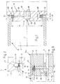
Beim sogenannten Innenhochdruck-Umformen (IHU) wird ein
Hohlprofil 10 durch einen in seinem Profilraum 12 herrschenden
Innendruck aufgeweitet. Zusätzlich kann das Hohlprofil
10 mittels eines an seiner Stirnkante 14 angreifenden
Stempels 16 axial nachgeschoben werden.In so-called hydroforming (IHU), a
Um den Hochdruck im Profilraum 12 zu halten, muss die
Stirnkante 14 des Hohlprofils 10 am Stempel 16 abgedichtet
anschlagen. Hierzu ist der Stempel 16 mit einer radialen
Schulterfläche 18 eines Außendurchmessers d versehen, an
welche ein zylindrischer Stempelansatz 20 eines kleineren
Durchmessers d1 anschließt. Die Höhe der zur Längsachse A
des Stempels 16 parallelen Umfangsfläche 22 des zylindrischen
Stempelabsatzes 20 ist in Fig. 1 mit h bezeichnet.In order to keep the high pressure in the
Am Übergang der ringförmigen Schulterfläche 18 zum Stempelansatz
20 ist in dessen Umfangsfläche 22 eine Ringnut 24
zur Aufnahme eines Dichtungsringes 26 eingeformt. Unter
diesem verläuft eine in das Tiefste -- also den Nutboden 27
-- der Ringnut 24 eingeformte sowie zum Querschnitt der
Ringnut 24 einer Breite b beidseits abgestufte Innennut 25
geringerer Breite e. Von dieser gehen -- im dargestellten
Ausführungsbeispiel sechs -- Radialkanäle 28 aus, die andernends
bei 29 in eine zentrische Ausnehmung 30 des Stempels
16 münden. Der Querschnitt dieser an sich zylindrischen
Ausnehmung 30 verjüngt sich nahe der Stempelinnen-
oder Stempelstirnfläche 17 in einem Bereich 32 konisch zu
einem Axial- oder Ausflusskanal 34 hin.At the transition from the
Zur Durchführung einer Verformung des Hohlprofils 10 fährt
der Stempel 16 mit seinem Dichtungsring 26 reibungslos in
dieses Werkstück bzw. Hohlprofil 10 ein; dabei entsteht
zwischen letzterem sowie der radialen Schulterfläche 18 des
Stempels 16 eine zu dichtende Fuge 36. Durch die Radialkanäle
28 strömt aus der zentrischen Ausnehmung 30 in die beschriebene
-- als Zuführraum dienende -- abgestufte Innennut
25 ein Wirkmedium und weitet den Dichtungsring 26 auf;
dieser legt sich vor jene Fuge 36, und das Wirkmedium
strömt gemäß Pfeil in Fig. 2 über die Innenkante 23 der
Ringnut 24 -- oder über Bohrungen -- in den Profilraum 12
ein. Sowohl die Innenkante 23 als auch die nicht dargestellten
Bohrungen können so ausgebildet sein, dass das
Wirkmedium erst in den Profilraum 12 fließt, wenn der Dichtungsring
26 an den kritischen Stellen vor der Fuge 36 --
diese abdichtend -- liegt.To carry out a deformation of the
In Fig. 1 nicht wiedergegeben ist ein in den Axialkanal 34
einsetzbares Druckventil, das in der Ausführung der Fig. 3
bei 38 angedeutet ist. Dieses wird so eingestellt, dass es
sich bei jenem Druck öffnet, unter welchem der Dichtungsring
26 der Dichtkante anliegt, und so den Einlauf eines
größeren Volumenstroms oder den verlustärmeren Einlauf des
Wirkmediums in den Profilraum 12 zuläßt.Not shown in FIG. 1 is an
Während des Kalibrierens des Hohlprofils 10 passt sich der
Dichtungsring 26 aus elastischem Werkstoff 26 der sich ändernden
Gestalt des Hohlprofiles 10 an. Wird in diesem der
Druck abgebaut, geht der Dichtungsring 26 in seine Ausgangslage
in die Ringnut 24 zurück, so dass der Dichtungsring
26 mit dem Stempel 16 wieder reibungslos aus dem Profilraum
12 ausgefahren zu werden vermag.During the calibration of the
Bei der Ausführung nach Fig. 3, 4 ist der Stempel 16a in
der Ebene seiner Schulterfläche 18 in einen Kopfteil 19 und
den zylindrischen Stempelansatz 20a zweigeteilt. In eine
einseitig hinterschnittene Schulternut 24a ist ein Dichtungsring
40 eingeschoben, der einen bandartigen Innenabschnitt
41 aufweist, aus dessen Querschnittsmitte eine an
ihren Kanten 42 angefaste Rippe 44 herausgeformt ist; ein
schmaler Randbereich des Innenabschnitts 41 des Dichtungsringes
40 ist einerseits in den hinterschnittenen Teil der
Schulternut 24a eingeschoben und anderseits von einer axialen
Ringrippe 46 des Kopfteils 19 übergriffen. Der querschnittlich
einem Hutquerschnitt ähnliche Dichtungsring 40
aus Polyurethan ist also beidseitig durch den zweigeteilten
Stahlstempel 16a eingefasst. Dadurch wird er zum einen
axial vorgespannt und bei einem gewissen Innendruck auch in
seiner Position gehalten. Durch den Ein-/oder Anbau des
schematisch dargestellten Drosselventils 38 ist gewährleistet,
dass bei Druckaufbau im Profil 10 zuerst Druck am
Dichtungsring 40 erzeugt wird, bevor der Innendruck im Profil
10 aufgebaut wird; das Ansprechen der Dichtung ist gewährleistet.In the embodiment of Fig. 3, 4, the
Fig. 5 zeigt ebenfalls einen zweigeteilten Stempel 16b aus
einem Kopfteil 19b und einem gesonderten zylindrischen
Stempelansatz 20b, der in einen Einsatzraum 48 des Kopfteils
19b eingesetzt ist. Die Ringnut 24 rechteckigen Querschnitts
nimmt den entsprechend gestalteten Dichtungsring
26 auf, der teilweise von der Seitenfläche 49 eines den
Einsatzraum 48 umgebenden Ringrandes 50 überdeckt ist;
letzterer bietet jene Schulterfläche 18 an. Fig. 5 also shows a two-
Beim Ausführungsbeispiel der Fig. 6 entspricht die Form des
Stempels 16c etwa der des Stempels 16 der Fig. 2, wobei allerdings
der Dichtungsring 26c der Umfangsfläche 22 aufliegt,
die durch eine achsparallel in die Schulterfläche 18
eingeformte Ringnut 24c über die Schulterfläche 18 hinaus
verlängert ist. Hier weist der Dichtungsring 26c andernends
eine an seine Außenkante angeordnete Schultereinformung 52
auf, in den eine Randrippe 54 eines Stempeldeckels 56 haltend
eingreift. Letzterer ist bei 58 mit dem zylindrischen
Stempelansatz 20c verschraubt.In the embodiment of FIG. 6, the shape of the
In Fig. 7 wird ein Stempel 16d mit einer axial durchgehenden
Fülleitung 60 für das Hohlprofil 10 sowie einer gesonderten
exzentrischen Druckleitung 62 vorgestellt, die mit
einem Radialabschnitt 64 an die Innennut 25 anschließt;
diese Druckleitung 62/64 dient der Ansteuerung des
Dichtungsrings 40a. Mit 66 ist eine Prall- oder
Verschleißeinlage aus Metall od. dgl. verschleißfestem
Werkstoff bezeichnet, die vor der Mündung eines
Radialabschnittes 64 an der Innennut 25 vorgesehen ist.FIG. 7 shows a
Claims (16)
dadurch gekennzeichnet,
dass an das als Ein- oder Mehrkammerprofil ausgebildete Hohlprofil (10) stirnseitig das den Profilraum (12) überdeckende Werkzeugteil (16, 16a bis 16d) angefügt und das Dichtungselement (26, 26c, 40, 40a) an eine zwischen dem Hohlprofil (10) sowie dem an dieses angeschlagenen stempelartigen Werkzeugteil (16, 16a, 16b, 16c, 16d) bestehende Fuge (36) angelegt wird.Method for forming a hollow profile or the like Workpiece (10) by means of an internal high pressure generated by a flowable active medium in the sealed profile space of the hollow profile, at least one sealing element (26) being guided radially outwards from the space (24) of a stamp-like tool part (16) by the active medium,
characterized,
that the tool part (16, 16 a to 16 d ) covering the profile space (12) and the sealing element (26, 26 c , 40, 40 a ) attached to the hollow profile (10) formed as a single or multi-chamber profile on the end face Hollow profile (10) and the existing on this stamp-like tool part (16, 16 a , 16 b , 16 c , 16 d ) existing joint (36) is created.
dadurch gekennzeichnet,
dass das stempelartige Werkzeugteil (16, 16a bis 16d) eine radiale Schulterfläche (18) als Anschlag für eine Stirnkante (14) des als Ein- oder Mehrkammerprofil ausgebildeten Hohlprofils (10) aufweist sowie am Umfang (22) eines in den Profilraum (12) einführbaren Stempelabsatzes (20, 20a, 20b, 20c) wenigstens eine Ringnut (24, 24a, 24c) für das Dichtungselement (26, 26c, 40, 40a) vorgesehen ist, das zur Stempellängsachse (A) hin zumindest einen Zuführraum (25) für das Wirkmedium überspannt sowie durch dieses vom Zuführraum abhebbar ist, wobei gegebenenfalls der in den Profilraum (12) einführbare Stempelabsatz an die ihn radial überragende Schulterfläche (18) angefügt ist, welche mit der anschlagenden Stirnkante (14) des Hohlprofils (10) eine Fuge (36) begrenzt, an welche das als Dichtungsring gestaltete Dichtungselement durch das Wirkmedium anlegbar ausgebildet ist. Device for reshaping a hollow profile or the like workpiece (10) by means of an internal high pressure generated by a flowable active medium in the sealed profile space (12) of the hollow profile (10), at least one sealing element (26) being removed from a space (24 ) a stamp-like tool part (16) is guided radially outwards, in particular for carrying out the method according to one of the preceding claims,
characterized,
that the stamp-like tool part (16, 16 a to 16 d ) has a radial shoulder surface (18) as a stop for an end edge (14) of the hollow profile (10) designed as a single or multi-chamber profile, and on the circumference (22) of a profile space ( 12) insertable stamp paragraph (20, 20 a , 20 b , 20 c ) at least one annular groove (24, 24 a , 24 c ) is provided for the sealing element (26, 26 c , 40, 40 a ), which is to the longitudinal axis of the stamp (A ) towards at least one feed space (25) for the active medium and can be lifted off from the feed space by this, where appropriate the stamp heel which can be inserted into the profile space (12) is attached to the radially projecting shoulder surface (18) which is in contact with the abutting front edge (14 ) of the hollow profile (10) delimits a joint (36) to which the sealing element designed as a sealing ring can be formed by the active medium.
Applications Claiming Priority (4)
| Application Number | Priority Date | Filing Date | Title |
|---|---|---|---|
| DE19846467 | 1998-10-08 | ||
| DE19846467 | 1998-10-08 | ||
| DE19909949 | 1999-03-06 | ||
| DE19909949A DE19909949B4 (en) | 1998-10-08 | 1999-03-06 | Device and method for reshaping a hollow profile or the like workpiece by means of hydroforming |
Publications (3)
| Publication Number | Publication Date |
|---|---|
| EP0995512A2 true EP0995512A2 (en) | 2000-04-26 |
| EP0995512A3 EP0995512A3 (en) | 2001-04-11 |
| EP0995512B1 EP0995512B1 (en) | 2003-10-22 |
Family
ID=26049387
Family Applications (1)
| Application Number | Title | Priority Date | Filing Date |
|---|---|---|---|
| EP99810889A Expired - Lifetime EP0995512B1 (en) | 1998-10-08 | 1999-10-01 | Method and device for sealing a hollow profile or similar workpiece in high pressure forming |
Country Status (3)
| Country | Link |
|---|---|
| EP (1) | EP0995512B1 (en) |
| AT (1) | ATE252429T1 (en) |
| ES (1) | ES2209372T3 (en) |
Cited By (5)
| Publication number | Priority date | Publication date | Assignee | Title |
|---|---|---|---|---|
| EP1208926A2 (en) * | 2000-11-15 | 2002-05-29 | Schuler Hydroforming GmbH & Co. KG | Device for hydroforming of hollow workpieces |
| EP1275448A3 (en) * | 2001-07-14 | 2004-01-02 | Benteler Automobiltechnik GmbH & Co. KG | Device for sealing the end of a tubular workpiece in an internal high pressure forming tool |
| EP1475168A1 (en) * | 2003-03-12 | 2004-11-10 | Forschungsgesellschaft Umformtechnik m.b.H. | Device for sealing the ends of a tubular workpiece for use in an hydroforming method |
| CN114618933A (en) * | 2022-03-01 | 2022-06-14 | 哈尔滨工业大学(威海) | Combined type inflation sealing method and device for pipe stamping deformation process |
| CN117619984A (en) * | 2024-01-25 | 2024-03-01 | 维格斯(上海)流体技术有限公司 | Water expansion forming machine for stainless steel tube processing |
Citations (3)
| Publication number | Priority date | Publication date | Assignee | Title |
|---|---|---|---|---|
| FR1245164A (en) * | 1959-01-09 | 1960-11-04 | Process for manufacturing round tubes and device for carrying out this process | |
| US3625040A (en) * | 1969-08-06 | 1971-12-07 | Koppy Tool Corp | Method and apparatus for forming articles from a tubular blank |
| JPS57165134A (en) * | 1981-04-03 | 1982-10-12 | Hitachi Ltd | Hydraulic bulge working device |
-
1999
- 1999-10-01 ES ES99810889T patent/ES2209372T3/en not_active Expired - Lifetime
- 1999-10-01 EP EP99810889A patent/EP0995512B1/en not_active Expired - Lifetime
- 1999-10-01 AT AT99810889T patent/ATE252429T1/en not_active IP Right Cessation
Patent Citations (3)
| Publication number | Priority date | Publication date | Assignee | Title |
|---|---|---|---|---|
| FR1245164A (en) * | 1959-01-09 | 1960-11-04 | Process for manufacturing round tubes and device for carrying out this process | |
| US3625040A (en) * | 1969-08-06 | 1971-12-07 | Koppy Tool Corp | Method and apparatus for forming articles from a tubular blank |
| JPS57165134A (en) * | 1981-04-03 | 1982-10-12 | Hitachi Ltd | Hydraulic bulge working device |
Non-Patent Citations (1)
| Title |
|---|
| PATENT ABSTRACTS OF JAPAN vol. 007, no. 005 (M-184), 11. Januar 1983 (1983-01-11) -& JP 57 165134 A (HITACHI SEISAKUSHO KK), 12. Oktober 1982 (1982-10-12) * |
Cited By (6)
| Publication number | Priority date | Publication date | Assignee | Title |
|---|---|---|---|---|
| EP1208926A2 (en) * | 2000-11-15 | 2002-05-29 | Schuler Hydroforming GmbH & Co. KG | Device for hydroforming of hollow workpieces |
| EP1208926A3 (en) * | 2000-11-15 | 2003-07-09 | Schuler Hydroforming GmbH & Co. KG | Device for hydroforming of hollow workpieces |
| EP1275448A3 (en) * | 2001-07-14 | 2004-01-02 | Benteler Automobiltechnik GmbH & Co. KG | Device for sealing the end of a tubular workpiece in an internal high pressure forming tool |
| EP1475168A1 (en) * | 2003-03-12 | 2004-11-10 | Forschungsgesellschaft Umformtechnik m.b.H. | Device for sealing the ends of a tubular workpiece for use in an hydroforming method |
| CN114618933A (en) * | 2022-03-01 | 2022-06-14 | 哈尔滨工业大学(威海) | Combined type inflation sealing method and device for pipe stamping deformation process |
| CN117619984A (en) * | 2024-01-25 | 2024-03-01 | 维格斯(上海)流体技术有限公司 | Water expansion forming machine for stainless steel tube processing |
Also Published As
| Publication number | Publication date |
|---|---|
| ES2209372T3 (en) | 2004-06-16 |
| EP0995512B1 (en) | 2003-10-22 |
| ATE252429T1 (en) | 2003-11-15 |
| EP0995512A3 (en) | 2001-04-11 |
Similar Documents
| Publication | Publication Date | Title |
|---|---|---|
| DE19813909B4 (en) | Hydraulically actuated non-return valve for the removal hydraulics in mining underground operations | |
| AT392624B (en) | DEVICE FOR TRANSPORTING MATERIAL BETWEEN SPACES OF DIFFERENT PRESSURES AND METHOD FOR OPERATING THE DEVICE | |
| DE102013204561A1 (en) | Seal arrangement for e.g. pressure medium actuation unit, has wall and movable seal lips whose axial grooves are provided in circumferential direction, where axial grooves of movable seal lip are interconnected over peripheral groove | |
| DE1259816B (en) | Piston for hydraulic pit ram or the like. | |
| EP0995512B1 (en) | Method and device for sealing a hollow profile or similar workpiece in high pressure forming | |
| DE19909949B4 (en) | Device and method for reshaping a hollow profile or the like workpiece by means of hydroforming | |
| DE1229480B (en) | Hydraulic pit ram | |
| DE2438666A1 (en) | HOLDER FOR A WORKING DEVICE | |
| DE102014000814B4 (en) | valve unit | |
| DE10134086A1 (en) | Method and device for connecting two components | |
| DE60025315T2 (en) | sealing arrangement | |
| DE102004009560B4 (en) | cylinder device | |
| DE1813237A1 (en) | Gate valve for abrasive materials | |
| DE102015110113A1 (en) | Gate valves | |
| DE19905849C1 (en) | Hollow profile component transforming unit comprises a stamper section with a flexible plastic section which forms part of its outer area | |
| EP0801015A2 (en) | Sealing system | |
| DE4307265C1 (en) | Device for the end-position damping of a piston in pressure-fluid cylinders | |
| AT394764B (en) | HYDRAULIC PRESSURE TRANSLATOR | |
| EP2924327A1 (en) | Multi-port valve | |
| DE102006028774A1 (en) | Tool fastening nut insert to hollow profile in automobile industry, includes resistance welding apparatus in which one electrode forms plunger with recess surrounding insert | |
| DE10153224B4 (en) | Method and device for molding and / or trimming a hollow body from a hollow profile or the like. workpiece | |
| DE19846323A1 (en) | Internal high pressure deformation process for making single or multi-chamber strip, comprises taking at least one sealing element radially outward through working fluid | |
| EP1350998B1 (en) | Valve | |
| DE10154439B4 (en) | hydraulic cylinders | |
| DE10005060B4 (en) | Device for controlling the tensile force of a rivet setting tool |
Legal Events
| Date | Code | Title | Description |
|---|---|---|---|
| PUAI | Public reference made under article 153(3) epc to a published international application that has entered the european phase |
Free format text: ORIGINAL CODE: 0009012 |
|
| AK | Designated contracting states |
Kind code of ref document: A2 Designated state(s): AT BE CH CY DE DK ES FI FR GB GR IE IT LI LU MC NL PT SE |
|
| AX | Request for extension of the european patent |
Free format text: AL;LT;LV;MK;RO;SI |
|
| PUAL | Search report despatched |
Free format text: ORIGINAL CODE: 0009013 |
|
| AK | Designated contracting states |
Kind code of ref document: A3 Designated state(s): AT BE CH CY DE DK ES FI FR GB GR IE IT LI LU MC NL PT SE |
|
| AX | Request for extension of the european patent |
Free format text: AL;LT;LV;MK;RO;SI |
|
| RAP1 | Party data changed (applicant data changed or rights of an application transferred) |
Owner name: ALCAN TECHNOLOGY & MANAGEMENT AG |
|
| 17P | Request for examination filed |
Effective date: 20011011 |
|
| AKX | Designation fees paid |
Free format text: AT BE CH CY DE DK ES FI FR GB GR IE IT LI LU MC NL PT SE |
|
| AXX | Extension fees paid |
Free format text: SI PAYMENT 20011011 |
|
| 17Q | First examination report despatched |
Effective date: 20020607 |
|
| GRAH | Despatch of communication of intention to grant a patent |
Free format text: ORIGINAL CODE: EPIDOS IGRA |
|
| GRAH | Despatch of communication of intention to grant a patent |
Free format text: ORIGINAL CODE: EPIDOS IGRA |
|
| GRAA | (expected) grant |
Free format text: ORIGINAL CODE: 0009210 |
|
| AK | Designated contracting states |
Kind code of ref document: B1 Designated state(s): AT BE CH CY DE DK ES FI FR GB GR IE IT LI LU MC NL PT SE |
|
| AX | Request for extension of the european patent |
Extension state: SI |
|
| PG25 | Lapsed in a contracting state [announced via postgrant information from national office to epo] |
Ref country code: NL Free format text: LAPSE BECAUSE OF FAILURE TO SUBMIT A TRANSLATION OF THE DESCRIPTION OR TO PAY THE FEE WITHIN THE PRESCRIBED TIME-LIMIT Effective date: 20031022 Ref country code: IT Free format text: LAPSE BECAUSE OF FAILURE TO SUBMIT A TRANSLATION OF THE DESCRIPTION OR TO PAY THE FEE WITHIN THE PRESCRIBED TIME-LIMIT;WARNING: LAPSES OF ITALIAN PATENTS WITH EFFECTIVE DATE BEFORE 2007 MAY HAVE OCCURRED AT ANY TIME BEFORE 2007. THE CORRECT EFFECTIVE DATE MAY BE DIFFERENT FROM THE ONE RECORDED. Effective date: 20031022 Ref country code: IE Free format text: LAPSE BECAUSE OF FAILURE TO SUBMIT A TRANSLATION OF THE DESCRIPTION OR TO PAY THE FEE WITHIN THE PRESCRIBED TIME-LIMIT Effective date: 20031022 Ref country code: FI Free format text: LAPSE BECAUSE OF FAILURE TO SUBMIT A TRANSLATION OF THE DESCRIPTION OR TO PAY THE FEE WITHIN THE PRESCRIBED TIME-LIMIT Effective date: 20031022 Ref country code: CY Free format text: LAPSE BECAUSE OF FAILURE TO SUBMIT A TRANSLATION OF THE DESCRIPTION OR TO PAY THE FEE WITHIN THE PRESCRIBED TIME-LIMIT Effective date: 20031022 |
|
| REG | Reference to a national code |
Ref country code: GB Ref legal event code: FG4D Free format text: NOT ENGLISH |
|
| REG | Reference to a national code |
Ref country code: CH Ref legal event code: EP |
|
| GBT | Gb: translation of ep patent filed (gb section 77(6)(a)/1977) |
Effective date: 20031022 |
|
| REG | Reference to a national code |
Ref country code: IE Ref legal event code: FG4D Free format text: GERMAN |
|
| REF | Corresponds to: |
Ref document number: 59907434 Country of ref document: DE Date of ref document: 20031127 Kind code of ref document: P |
|
| PG25 | Lapsed in a contracting state [announced via postgrant information from national office to epo] |
Ref country code: SE Free format text: LAPSE BECAUSE OF FAILURE TO SUBMIT A TRANSLATION OF THE DESCRIPTION OR TO PAY THE FEE WITHIN THE PRESCRIBED TIME-LIMIT Effective date: 20040122 Ref country code: GR Free format text: LAPSE BECAUSE OF FAILURE TO SUBMIT A TRANSLATION OF THE DESCRIPTION OR TO PAY THE FEE WITHIN THE PRESCRIBED TIME-LIMIT Effective date: 20040122 Ref country code: DK Free format text: LAPSE BECAUSE OF FAILURE TO SUBMIT A TRANSLATION OF THE DESCRIPTION OR TO PAY THE FEE WITHIN THE PRESCRIBED TIME-LIMIT Effective date: 20040122 |
|
| NLV1 | Nl: lapsed or annulled due to failure to fulfill the requirements of art. 29p and 29m of the patents act | ||
| REG | Reference to a national code |
Ref country code: ES Ref legal event code: FG2A Ref document number: 2209372 Country of ref document: ES Kind code of ref document: T3 |
|
| REG | Reference to a national code |
Ref country code: IE Ref legal event code: FD4D |
|
| ET | Fr: translation filed | ||
| PLBE | No opposition filed within time limit |
Free format text: ORIGINAL CODE: 0009261 |
|
| STAA | Information on the status of an ep patent application or granted ep patent |
Free format text: STATUS: NO OPPOSITION FILED WITHIN TIME LIMIT |
|
| PG25 | Lapsed in a contracting state [announced via postgrant information from national office to epo] |
Ref country code: LU Free format text: LAPSE BECAUSE OF NON-PAYMENT OF DUE FEES Effective date: 20041001 Ref country code: GB Free format text: LAPSE BECAUSE OF NON-PAYMENT OF DUE FEES Effective date: 20041001 Ref country code: AT Free format text: LAPSE BECAUSE OF NON-PAYMENT OF DUE FEES Effective date: 20041001 |
|
| PG25 | Lapsed in a contracting state [announced via postgrant information from national office to epo] |
Ref country code: ES Free format text: LAPSE BECAUSE OF NON-PAYMENT OF DUE FEES Effective date: 20041002 |
|
| 26N | No opposition filed |
Effective date: 20040723 |
|
| PG25 | Lapsed in a contracting state [announced via postgrant information from national office to epo] |
Ref country code: MC Free format text: LAPSE BECAUSE OF NON-PAYMENT OF DUE FEES Effective date: 20041031 Ref country code: LI Free format text: LAPSE BECAUSE OF NON-PAYMENT OF DUE FEES Effective date: 20041031 Ref country code: CH Free format text: LAPSE BECAUSE OF NON-PAYMENT OF DUE FEES Effective date: 20041031 Ref country code: BE Free format text: LAPSE BECAUSE OF NON-PAYMENT OF DUE FEES Effective date: 20041031 |
|
| BERE | Be: lapsed |
Owner name: *ALCAN TECHNOLOGY & MANAGEMENT A.G. Effective date: 20041031 |
|
| GBPC | Gb: european patent ceased through non-payment of renewal fee |
Effective date: 20041001 |
|
| REG | Reference to a national code |
Ref country code: CH Ref legal event code: PL |
|
| PG25 | Lapsed in a contracting state [announced via postgrant information from national office to epo] |
Ref country code: FR Free format text: LAPSE BECAUSE OF NON-PAYMENT OF DUE FEES Effective date: 20050630 |
|
| REG | Reference to a national code |
Ref country code: FR Ref legal event code: ST |
|
| REG | Reference to a national code |
Ref country code: ES Ref legal event code: FD2A Effective date: 20041002 |
|
| PGFP | Annual fee paid to national office [announced via postgrant information from national office to epo] |
Ref country code: DE Payment date: 20061130 Year of fee payment: 8 |
|
| BERE | Be: lapsed |
Owner name: *ALCAN TECHNOLOGY & MANAGEMENT A.G. Effective date: 20041031 |
|
| PG25 | Lapsed in a contracting state [announced via postgrant information from national office to epo] |
Ref country code: PT Free format text: LAPSE BECAUSE OF NON-PAYMENT OF DUE FEES Effective date: 20040322 |
|
| PG25 | Lapsed in a contracting state [announced via postgrant information from national office to epo] |
Ref country code: DE Free format text: LAPSE BECAUSE OF NON-PAYMENT OF DUE FEES Effective date: 20080501 |