EP0995267B1 - Multiple mode direct conversion receiver - Google Patents
Multiple mode direct conversion receiver Download PDFInfo
- Publication number
- EP0995267B1 EP0995267B1 EP98931173A EP98931173A EP0995267B1 EP 0995267 B1 EP0995267 B1 EP 0995267B1 EP 98931173 A EP98931173 A EP 98931173A EP 98931173 A EP98931173 A EP 98931173A EP 0995267 B1 EP0995267 B1 EP 0995267B1
- Authority
- EP
- European Patent Office
- Prior art keywords
- quadrature
- signals
- receiver
- phase
- signal
- Prior art date
- Legal status (The legal status is an assumption and is not a legal conclusion. Google has not performed a legal analysis and makes no representation as to the accuracy of the status listed.)
- Expired - Lifetime
Links
Images

Classifications
-
- H—ELECTRICITY
- H04—ELECTRIC COMMUNICATION TECHNIQUE
- H04B—TRANSMISSION
- H04B1/00—Details of transmission systems, not covered by a single one of groups H04B3/00 - H04B13/00; Details of transmission systems not characterised by the medium used for transmission
- H04B1/06—Receivers
- H04B1/16—Circuits
-
- H—ELECTRICITY
- H04—ELECTRIC COMMUNICATION TECHNIQUE
- H04W—WIRELESS COMMUNICATION NETWORKS
- H04W88/00—Devices specially adapted for wireless communication networks, e.g. terminals, base stations or access point devices
- H04W88/02—Terminal devices
- H04W88/06—Terminal devices adapted for operation in multiple networks or having at least two operational modes, e.g. multi-mode terminals
-
- H—ELECTRICITY
- H03—ELECTRONIC CIRCUITRY
- H03J—TUNING RESONANT CIRCUITS; SELECTING RESONANT CIRCUITS
- H03J5/00—Discontinuous tuning; Selecting predetermined frequencies; Selecting frequency bands with or without continuous tuning in one or more of the bands, e.g. push-button tuning, turret tuner
- H03J5/24—Discontinuous tuning; Selecting predetermined frequencies; Selecting frequency bands with or without continuous tuning in one or more of the bands, e.g. push-button tuning, turret tuner with a number of separate pretuned tuning circuits or separate tuning elements selectively brought into circuit, e.g. for waveband selection or for television channel selection
- H03J5/242—Discontinuous tuning; Selecting predetermined frequencies; Selecting frequency bands with or without continuous tuning in one or more of the bands, e.g. push-button tuning, turret tuner with a number of separate pretuned tuning circuits or separate tuning elements selectively brought into circuit, e.g. for waveband selection or for television channel selection used exclusively for band selection
- H03J5/244—Discontinuous tuning; Selecting predetermined frequencies; Selecting frequency bands with or without continuous tuning in one or more of the bands, e.g. push-button tuning, turret tuner with a number of separate pretuned tuning circuits or separate tuning elements selectively brought into circuit, e.g. for waveband selection or for television channel selection used exclusively for band selection using electronic means
-
- H—ELECTRICITY
- H04—ELECTRIC COMMUNICATION TECHNIQUE
- H04B—TRANSMISSION
- H04B1/00—Details of transmission systems, not covered by a single one of groups H04B3/00 - H04B13/00; Details of transmission systems not characterised by the medium used for transmission
- H04B1/005—Details of transmission systems, not covered by a single one of groups H04B3/00 - H04B13/00; Details of transmission systems not characterised by the medium used for transmission adapting radio receivers, transmitters andtransceivers for operation on two or more bands, i.e. frequency ranges
- H04B1/0053—Details of transmission systems, not covered by a single one of groups H04B3/00 - H04B13/00; Details of transmission systems not characterised by the medium used for transmission adapting radio receivers, transmitters andtransceivers for operation on two or more bands, i.e. frequency ranges with common antenna for more than one band
- H04B1/0057—Details of transmission systems, not covered by a single one of groups H04B3/00 - H04B13/00; Details of transmission systems not characterised by the medium used for transmission adapting radio receivers, transmitters andtransceivers for operation on two or more bands, i.e. frequency ranges with common antenna for more than one band using diplexing or multiplexing filters for selecting the desired band
-
- H—ELECTRICITY
- H04—ELECTRIC COMMUNICATION TECHNIQUE
- H04B—TRANSMISSION
- H04B1/00—Details of transmission systems, not covered by a single one of groups H04B3/00 - H04B13/00; Details of transmission systems not characterised by the medium used for transmission
- H04B1/005—Details of transmission systems, not covered by a single one of groups H04B3/00 - H04B13/00; Details of transmission systems not characterised by the medium used for transmission adapting radio receivers, transmitters andtransceivers for operation on two or more bands, i.e. frequency ranges
- H04B1/0053—Details of transmission systems, not covered by a single one of groups H04B3/00 - H04B13/00; Details of transmission systems not characterised by the medium used for transmission adapting radio receivers, transmitters andtransceivers for operation on two or more bands, i.e. frequency ranges with common antenna for more than one band
- H04B1/006—Details of transmission systems, not covered by a single one of groups H04B3/00 - H04B13/00; Details of transmission systems not characterised by the medium used for transmission adapting radio receivers, transmitters andtransceivers for operation on two or more bands, i.e. frequency ranges with common antenna for more than one band using switches for selecting the desired band
-
- H—ELECTRICITY
- H04—ELECTRIC COMMUNICATION TECHNIQUE
- H04B—TRANSMISSION
- H04B1/00—Details of transmission systems, not covered by a single one of groups H04B3/00 - H04B13/00; Details of transmission systems not characterised by the medium used for transmission
- H04B1/38—Transceivers, i.e. devices in which transmitter and receiver form a structural unit and in which at least one part is used for functions of transmitting and receiving
- H04B1/40—Circuits
- H04B1/403—Circuits using the same oscillator for generating both the transmitter frequency and the receiver local oscillator frequency
- H04B1/406—Circuits using the same oscillator for generating both the transmitter frequency and the receiver local oscillator frequency with more than one transmission mode, e.g. analog and digital modes
Definitions
- the present invention relates generally to multiple-band wireless communication devices and systems. More particularly, the present invention relates to multiple-band wireless communication devices and systems incorporating direct conversion rather than superheterodyne circuitry.
- GSM Global System for Mobile communications
- PCS Personal Communication Services
- DCS Digital Communication System
- wireless communication devices are of the single-band type, because it is difficult to incorporate multi-band capabilities into a wireless communication device, given the size and cost limitations of typical devices.
- most wireless communication devices use receivers which incorporate superheterodyne circuitry, in which received signals at a first frequency are converted to one or more second, intermediate frequencies for processing by the receiver. The intermediate frequencies can differ substantially from the first frequency.
- An exemplary known superheterodyne receiver is shown in FIG. 1, in which signals are received at an antenna 10, filtered in a band-pass filter 12, amplified in an amplifier 14, and converted to a first intermediate frequency by local oscillator LO1 and mixer 16.
- US 5 564 076 shows a dual mode digital radio transceiver for adapted to receive signals from a terrestrial network and a satellite network, respectively. In the terrestrial mode the receiver uses direct conversion, i.e. the received frequency band is converted directly to baseband. In the satellite mode, however, intermediate frequency conversion is used similarly to the known superheterodyne receiver described above.
- the received satellite frequency band is first converted to an intermediate frequency band, which is in the same range as the terrestrial frequency band received in the terrestrial mode, and then this intermediate frequency band is converted down to baseband in the circuitry used for converting the terrestrial frequency band.
- this receiver has to process signals at multiple frequencies.
- a wireless communication device it would be desirable for a wireless communication device to be able to receive signals at multiple frequency bands while minimizing the duplication of receiver hardware.
- the present invention overcomes the above-described problems, and provides additional advantages, by providing for a wireless communication device which can receive signals at multiple frequency bands without requiring significant hardware duplication.
- the wireless communication device according to the present invention uses direct conversion, wherein the use of intermediate frequencies is either eliminated or any frequency conversion is limited to frequencies within the bandwidth of the received signals.
- a multiple-band communication receiver includes an antenna or other receiving means for receiving communication signals on one of a plurality of frequency bands; one or more band pass filters for filtering communication signals in each of the plurality of frequency bands; amplifiers for selectively amplifying filtered communication signals in one of the plurality of bands; one or more quadrature generators for generating in-phase and quadrature signals from the amplified signals; low pass filters for filtering the in-phase and quadrature signals; and baseband processing circuitry for processing the low-pass filtered in-phase and quadrature signals.
- the quadrature signals are within the frequency range of the received signals.
- certain portions of the receiver circuitry are re-used to simplify the circuit.
- further embodiments of the invention are disclosed in which low-noise amplifiers are divided into frequency-specific amplifier portions and generic amplifier portions and in which mixers, quadrature generators, and/or voltage-controlled oscillators are re-used.
- low pass filters can be used to filter the quadrature signals in place of the band pass filters required in a typical superheterodyne receiver. Since low pass filters are more easily implemented than band pass filters, the receiver circuit can be further simplified.
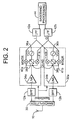
- FIG. 2 shows a block diagram of a direct conversion receiver according to a first preferred embodiment of the present invention.
- the receiver includes an antenna 10 for receiving signals and a bandsplitter 30 for splitting the received signals into first and second bands.
- First and second band pass filters 12a and 12b filter the split signals in the first and second bands, respectively.
- These band pass filters are frequency (band) specific, and can be omitted if the receiver linearity is relatively high.
- bandsplitter 30 can be omitted if band pass filters are used. In most cases, band pass filters are desirable to minimize power consumption.
- a single multiband filter having one input and multiple outputs (one output per band) could replace the bandsplitter 30 and band pass filters 12a and 12b.
- the filtered signals output by filters 12a and 12b are supplied to processing units 32a and 32b, respectively, which convert the bandpass-filtered signals into baseband signals for further processing.
- Processing units 32a and 32b generate in-phase and quadrature components of the signals in the first frequency band or second frequency band, depending upon which band is selected. Band selection can be performed by the subscriber or by a control signal supplied with the received communication signal.
- Included within processing units 32a and 32b are low-noise amplifiers 34a and 34b, respectively, and mixing circuitry. Since the mixing circuitry of each processing unit 32a and 32b is substantially identical, the mixing circuitry of processing unit 32a only will be described.
- the mixing circuitry of processing unit 32a includes a voltage controlled oscillator (VCO) 36a for generating an oscillator signal, a quadrature generator 38a for separating the oscillator signal into in-phase (I) and quadrature (Q) components (i.e., signals separated by 90° in phase), and mixers 40a and 41a for mixing the I signal and Q signal, respectively, with the amplified signal output by amplifier 34a.
- VCO voltage controlled oscillator
- quadrature generator 38a for separating the oscillator signal into in-phase (I) and quadrature (Q) components (i.e., signals separated by 90° in phase)
- mixers 40a and 41a for mixing the I signal and Q signal, respectively, with the amplified signal output by amplifier 34a.
- the mixing circuitry of processing unit 32b similarly outputs I and Q signals in the same frequency band.
- the quadrature generators 38a and 38b generate quadrature signals which drive the mixers.
- the frequencies of the signals output by mixers 40a,b and 41a,b are within the same frequency range as the bandwidth of the received signals.
- oscillators 36a and 36b are in the same frequency range as the received signals, although the first and second bands can have different bandwidths.
- many hardware components of the receiver can be re-used, since there is no conversion of signals to an intermediate frequency outside of the frequency range of the bandwidth of the received signals.
- the low pass filters 42a and 42b are re-used.
- the in-phase (I) signals and quadrature (Q) signals output by the selected processing unit are provided to an in-phase low pass filter 42a and a quadrature low pass filter 42b, respectively.
- These low pass filters 42a and 42b preferably have programmable bandwidths to enable the receiver to accommodate two bands having different bandwidths.
- the filtered I and Q signals are then passed to baseband processing circuitry 44, which can be conventional baseband processing circuitry as is well-known in the art. It will be appreciated that since direct conversion avoids the use of intermediate frequencies outside of the range of the received signals, the signals output by processing units 32a and 32b can be filtered in low pass filters rather than band pass filters.
- band pass filters are necessary. This difference provides a significant advantage, since low pass filters can be implemented more easily than band pass filters, and programmable low pass filters are more easily implemented than programmable band pass filters. Because the channel selection filtering can be performed with programmable low pass filters, it is possible to implement a dual band receiver with the two bands having different bandwidths.
- a low pass filter can be designed relatively easily with a programmable bandwidth if it is integrated either as an analog or as a digital filter.
- bandpass filters are typically discrete filters which cannot be programmed for different bandwidths.
- the relatively simple architecture of the direct-conversion receiver of FIG. 2 simplifies the frequency planning of the wireless communication device. It should be appreciated that while a two-band receiver is shown, the principles of the invention can be applied to design a receiver having three or more bands.
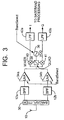
- FIG. 3 shows a block diagram of a second embodiment of the present invention.
- a single mixing circuit with a single voltage controlled oscillator (VCO) 36 and mixers 40 and 41, is used to mix the amplified signals generated in each frequency band.
- the mixing circuitry generates in-phase (I) and quadrature (Q) signals which are filtered in low pass filters 42a and 42b.
- the VCO 36 should have a relatively large bandwidth, sufficient to include all of the frequency bands which the receiver is capable of receiving.
- the VCO 36 can be switchable between multiple oscillation frequencies.
- the quadrature generator 38 can be replaced by a frequency divider which generates quadrature local oscillator (LO) signals from the oscillation signal generated by VCO 36.
- LO local oscillator
- a differential signal at a frequency 2f is divided by two, and the rising edge of each signal controls the edge at the divided signal. Since one half wavelength at 2f is equal to one quarter of a wavelength at frequency f, the resulting signals are quadrature signals.
- the VCO 36 must operate at an appropriate multiple of the desired LO frequency; for example, for a quadrature generator operating at one or two frequencies, the frequency divider divides by 2 or 2 and 4, respectively. This approach can require a better semiconductor process with a higher f T or a higher current consumption; however, this approach is a robust wideband implementation and can reduce spurious emissions.
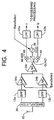
- FIG. 4 shows a block diagram of a third embodiment of the present invention.
- This embodiment is substantially similar to the embodiment of FIG. 3, except that the amplifier means is divided.
- the low noise amplifiers 34a and 34b are bandspecific, and a low noise amplifier 34c is provided which is generic for two or more bands, or which includes a portion of a low noise amplifier such that a combination of, for example, 34a and 34c form a complete low raise amplifier (in other words, a portion of a low noise amplifier can be common to multiple bands).
- splitting the low noise amplifier means into band-specifi c and generic components allows the first portion of the low noise amplifier means (amplifiers 34a and 34b) to provide a band select function, and reduces the overall circuit complexity by re-using a portion of the low-noise amplifier circuitry. If the multiple-band receiver is to receive GSM and DCS signals, it is preferable to use bandspecific LNAs for each band because current consumption will be less in the GSM LNA compared to the DCS LNA; therefore, the current consumption of the receiver can be reduced by using a split amplifier.
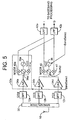
- FIG. 5 shows a block diagram of a fourth embodiment of the present invention.
- the embodiment of FIG. 5 shows a three band receiver for receiving signals on three bands (e.g., GSM, DCS, and PCS).
- GSM Global System for Mobile Communications
- the bandsplitter 30 splits the received signal into three bands, and band pass filters 12a, 12b, and 12c filter the split signals as appropriate for the three bands (in this example, GSM, DCS, and PCS, respectively).
- the GSM signal branch includes a processing unit 32a which is substantially identical to the similarly-designated unit in FIG. 2.
- Processing unit 32a outputs in-phase (I) and quadrature (Q) signals to in-phase and quadrature low pass filters 42a and 42b, respectively.
- the DCS and PCS branches of this circuit include separate low-noise amplifiers 34b and 34d, and a single mixing circuitry unit that includes a tunable, programmable, or switchable high bandwidth VCO 36 as described above with respect to FIG. 4.
- the common mixing circuitry unit generates in-phase and quadrature signals and provides these signals to the in-phase and quadrature low pass filters 42a and 42b, respectively.
- FIG. 5 could easily be modified to include band-specific and common low-noise amplifiers for the branches sharing a single mixing circuit and VCO.
- band-specific and common low-noise amplifiers for the branches sharing a single mixing circuit and VCO.
- direct conversion By providing for a relatively low number of frequency conversion operations, each of which results in a frequency within the frequency range of the bandwidth of the received signals (i.e., direct conversion), significant signal processing advantages can be achieved.
- a multiple-mode communication receiver can be greatly simplified with components such as LNAs, quadrature generators, mixers, VCOs and low pass filters re-used.
- low pass filters can be used in place of the band pass filters typically required for superheterodyne circuitry. Because programmable low pass filters are more easily implemented than band pass filters, the receiver circuitry can be further simplified.
Landscapes
- Engineering & Computer Science (AREA)
- Computer Networks & Wireless Communication (AREA)
- Signal Processing (AREA)
- Superheterodyne Receivers (AREA)
- Circuits Of Receivers In General (AREA)
- Digital Transmission Methods That Use Modulated Carrier Waves (AREA)
- Transceivers (AREA)
Abstract
Description
- The present invention relates generally to multiple-band wireless communication devices and systems. More particularly, the present invention relates to multiple-band wireless communication devices and systems incorporating direct conversion rather than superheterodyne circuitry.
- As the field of wireless communications continues to develop at a rapid pace, the increasing number of systems and frequency bands in use conflicts with the consumer demand for increased mobility. That is, a problem results when different consumers subscribe to wireless communication systems using different technical standards. To avoid this problem, global standardized systems have been proposed in which the same frequency band is in use by all wireless communication systems. However, this solution is impractical because wireless communication systems are operators desire to maximize the return on their inv estment in the many different systems which already exist or which are already under development. Further, history suggests that it would be extremely difficult for all manufacturers to agree on a single standardized system.
- An alternative solution to the problem of maximizing mobility where multiple wireless communication systems exist is to incorporate dual- or multi-mode capabilities in a wireless communication device to enable a subscriber to communicate on different wireless communication systems. This solution is particularly desirable where the different wireless communication systems operate at different carrier frequencies or frequency bands, but use the same modulation scheme and same baseband processing scheme. The well-known Global System for Mobile communications (GSM), Personal Communication Services (PCS), and Digital Communication System (DCS) systems share such similarities.
- However, almost all known wireless communication devices are of the single-band type, because it is difficult to incorporate multi-band capabilities into a wireless communication device, given the size and cost limitations of typical devices. Further, most wireless communication devices use receivers which incorporate superheterodyne circuitry, in which received signals at a first frequency are converted to one or more second, intermediate frequencies for processing by the receiver. The intermediate frequencies can differ substantially from the first frequency. An exemplary known superheterodyne receiver is shown in FIG. 1, in which signals are received at an
antenna 10, filtered in a band-pass filter 12, amplified in anamplifier 14, and converted to a first intermediate frequency by local oscillator LO1 andmixer 16. The signal at the first intermediate frequency is then processed byband pass filter 18 andamplifier 20, and converted to a second intermediate frequency by local oscillator LO2 andmixer 22. This second intermediate frequency signal is filtered inband pass filter 24 and is processed by further circuitry (not shown). Because a superheterodyne receiver processes signals at multiple frequencies, it is difficult to provide multi-mode capabilities without duplicating many receiver hardware components. US 5 564 076 shows a dual mode digital radio transceiver for adapted to receive signals from a terrestrial network and a satellite network, respectively. In the terrestrial mode the receiver uses direct conversion, i.e. the received frequency band is converted directly to baseband. In the satellite mode, however, intermediate frequency conversion is used similarly to the known superheterodyne receiver described above. The received satellite frequency band is first converted to an intermediate frequency band, which is in the same range as the terrestrial frequency band received in the terrestrial mode, and then this intermediate frequency band is converted down to baseband in the circuitry used for converting the terrestrial frequency band. Thus also this receiver has to process signals at multiple frequencies. - Accordingly, it would be desirable for a wireless communication device to be able to receive signals at multiple frequency bands while minimizing the duplication of receiver hardware.
- The present invention overcomes the above-described problems, and provides additional advantages, by providing for a wireless communication device which can receive signals at multiple frequency bands without requiring significant hardware duplication. To achieve this result, the wireless communication device according to the present invention uses direct conversion, wherein the use of intermediate frequencies is either eliminated or any frequency conversion is limited to frequencies within the bandwidth of the received signals.
- According to a first embodiment of the present invention, a multiple-band communication receiver includes an antenna or other receiving means for receiving communication signals on one of a plurality of frequency bands; one or more band pass filters for filtering communication signals in each of the plurality of frequency bands; amplifiers for selectively amplifying filtered communication signals in one of the plurality of bands; one or more quadrature generators for generating in-phase and quadrature signals from the amplified signals; low pass filters for filtering the in-phase and quadrature signals; and baseband processing circuitry for processing the low-pass filtered in-phase and quadrature signals. The quadrature signals are within the frequency range of the received signals.
- In accordance with the invention, certain portions of the receiver circuitry are re-used to simplify the circuit. Thus, further embodiments of the invention are disclosed in which low-noise amplifiers are divided into frequency-specific amplifier portions and generic amplifier portions and in which mixers, quadrature generators, and/or voltage-controlled oscillators are re-used. Because direct conversion principles are employed, low pass filters can be used to filter the quadrature signals in place of the band pass filters required in a typical superheterodyne receiver. Since low pass filters are more easily implemented than band pass filters, the receiver circuit can be further simplified.
- A more complete understanding of the present invention can be obtained upon reading the following Detailed Description of the Preferred Embodiments, in conjunction with the accompanying drawings, in which like reference indicia are used to designate like elements, and in which:
- FIG. 1 is a block diagram of a conventional superheterodyne receiver;
- FIG. 2 is a block diagram of a direct-conversion receiver according to a first preferred embodiment of the present invention;
- FIG. 3 is a block diagram of a direct-conversion receiver according to a second preferred embodiment of the present invention;
- FIG. 4 is a block diagram of a direct-conversion receiver according to a third preferred embodiment of the present invention; and
- FIG. 5 is a block diagram of a direct-conversion receiver according to a fourth preferred embodiment of the present invention.
-
- FIG. 2 shows a block diagram of a direct conversion receiver according to a first preferred embodiment of the present invention. The receiver includes an
antenna 10 for receiving signals and abandsplitter 30 for splitting the received signals into first and second bands. First and secondband pass filters bandsplitter 30 can be omitted if band pass filters are used. In most cases, band pass filters are desirable to minimize power consumption. As another alternative, a single multiband filter having one input and multiple outputs (one output per band) could replace thebandsplitter 30 andband pass filters filters processing units 32a and 32b, respectively, which convert the bandpass-filtered signals into baseband signals for further processing.Processing units 32a and 32b generate in-phase and quadrature components of the signals in the first frequency band or second frequency band, depending upon which band is selected. Band selection can be performed by the subscriber or by a control signal supplied with the received communication signal. Included withinprocessing units 32a and 32b are low-noise amplifiers processing unit 32a and 32b is substantially identical, the mixing circuitry ofprocessing unit 32a only will be described. The mixing circuitry ofprocessing unit 32a includes a voltage controlled oscillator (VCO) 36a for generating an oscillator signal, aquadrature generator 38a for separating the oscillator signal into in-phase (I) and quadrature (Q) components (i.e., signals separated by 90° in phase), andmixers amplifier 34a. The mixing circuitry of processing unit 32b similarly outputs I and Q signals in the same frequency band. Thequadrature generators - In accordance with the direct conversion principle, the frequencies of the signals output by
mixers 40a,b and 41a,b are within the same frequency range as the bandwidth of the received signals. Thus,oscillators low pass filters - The in-phase (I) signals and quadrature (Q) signals output by the selected processing unit are provided to an in-phase
low pass filter 42a and a quadraturelow pass filter 42b, respectively. Theselow pass filters baseband processing circuitry 44, which can be conventional baseband processing circuitry as is well-known in the art. It will be appreciated that since direct conversion avoids the use of intermediate frequencies outside of the range of the received signals, the signals output byprocessing units 32a and 32b can be filtered in low pass filters rather than band pass filters. In contrast, because a superheterodyne receiver uses intermediate frequencies outside of the range of the received signals, band pass filters are necessary. This difference provides a significant advantage, since low pass filters can be implemented more easily than band pass filters, and programmable low pass filters are more easily implemented than programmable band pass filters. Because the channel selection filtering can be performed with programmable low pass filters, it is possible to implement a dual band receiver with the two bands having different bandwidths. A low pass filter can be designed relatively easily with a programmable bandwidth if it is integrated either as an analog or as a digital filter. In contrast, bandpass filters are typically discrete filters which cannot be programmed for different bandwidths. Further, the relatively simple architecture of the direct-conversion receiver of FIG. 2 simplifies the frequency planning of the wireless communication device. It should be appreciated that while a two-band receiver is shown, the principles of the invention can be applied to design a receiver having three or more bands. - FIG. 3 shows a block diagram of a second embodiment of the present invention. In this embodiment, a single mixing circuit, with a single voltage controlled oscillator (VCO) 36 and
mixers low pass filters VCO 36 should have a relatively large bandwidth, sufficient to include all of the frequency bands which the receiver is capable of receiving. Alternatively, theVCO 36 can be switchable between multiple oscillation frequencies. Also, thequadrature generator 38 can be replaced by a frequency divider which generates quadrature local oscillator (LO) signals from the oscillation signal generated byVCO 36. By dividing a signal's frequency by two, it is possible to generate two quadrature signals. A differential signal at a frequency 2f is divided by two, and the rising edge of each signal controls the edge at the divided signal. Since one half wavelength at 2f is equal to one quarter of a wavelength at frequency f, the resulting signals are quadrature signals. If a frequency divider is used, theVCO 36 must operate at an appropriate multiple of the desired LO frequency; for example, for a quadrature generator operating at one or two frequencies, the frequency divider divides by 2 or 2 and 4, respectively. This approach can require a better semiconductor process with a higher fT or a higher current consumption; however, this approach is a robust wideband implementation and can reduce spurious emissions. While this embodiment shows the use of a single quadrature generator and a single VCO, it should be appreciated that multiple VCO's (with appropriate switching means) can be used with a si ngle quadrature generator, or multiple VCO's can be used with multiple quadrature generators, or a single VCO can be used with multiple quadrature generators. - FIG. 4 shows a block diagram of a third embodiment of the present invention. This embodiment is substantially similar to the embodiment of FIG. 3, except that the amplifier means is divided. In particular, the
low noise amplifiers low noise amplifier 34c is provided which is generic for two or more bands, or which includes a portion of a low noise amplifier such that a combination of, for example, 34a and 34c form a complete low raise amplifier (in other words, a portion of a low noise amplifier can be common to multiple bands). Splitting the low noise amplifier means into band-specifi c and generic components allows the first portion of the low noise amplifier means (amplifiers - FIG. 5 shows a block diagram of a fourth embodiment of the present invention. The embodiment of FIG. 5 shows a three band receiver for receiving signals on three bands (e.g., GSM, DCS, and PCS). This embodiment combines the features of the embodiments of FIG. 2 and FIG 3; it will be appreciated that other combinations can be designed. In this embodiment, the
bandsplitter 30 splits the received signal into three bands, andband pass filters processing unit 32a which is substantially identical to the similarly-designated unit in FIG. 2.Processing unit 32a outputs in-phase (I) and quadrature (Q) signals to in-phase and quadraturelow pass filters noise amplifiers high bandwidth VCO 36 as described above with respect to FIG. 4. The common mixing circuitry unit generates in-phase and quadrature signals and provides these signals to the in-phase and quadraturelow pass filters - It will be appreciated that many circuit combinations other than those described above can be designed in accordance with the principles of the present invention. For example, the embodiment of FIG. 5 could easily be modified to include band-specific and common low-noise amplifiers for the branches sharing a single mixing circuit and VCO. By providing for a relatively low number of frequency conversion operations, each of which results in a frequency within the frequency range of the bandwidth of the received signals (i.e., direct conversion), significant signal processing advantages can be achieved. In particular, a multiple-mode communication receiver can be greatly simplified with components such as LNAs, quadrature generators, mixers, VCOs and low pass filters re-used. Further, as a result of using the direct conversion principle, low pass filters can be used in place of the band pass filters typically required for superheterodyne circuitry. Because programmable low pass filters are more easily implemented than band pass filters, the receiver circuitry can be further simplified.
- While the foregoing description includes numerous details and specificities, it is to be understood that these are for purposes of explanation only. Many modifications will be readily apparent to those of ordinary skill in the art which are clearly within the scope of the invention, as defined by the following claims and their legal equivalents.
Claims (18)
- A multiple-band communication receiver, comprising:characterized in that the multiple-band communication receiver is adapted to use direct conversion for converting all of the received communication signals in any one of the plurality of frequency bands.receiving means (10) for receiving communication signals in any one of a plurality of frequency bands, the received communication signals having a bandwidth;amplifier means (34a, 34b; 34c; 34d) for selectively amplifying the received communication signals in one of the plurality of frequency bands;quadrature generation means (40, 41; 40a, 41 a, 40b, 41b) for generating in-phase and quadrature signals from the amplified signals;low pass filtering means (42a, 42b) for filtering the in-phase and quadrature signals; andbaseband processing means (44) for processing the filtered in-phase and quadrature signals,
- The receiver of claim 1, further comprising band pass filtering means (12a, 12b) for filtering communication signals in each of the plurality of frequency bands.
- The receiver of claim 1, wherein the quadrature generation means includes mixing means (40a, 40b, 41b, 41b) for mixing the amplified signals with in-phase and quadrature oscillator signals, the in-phase and quadrature oscillator signals being of a frequency within the bandwidth of the received communication signals.
- The receiver of claim 1, wherein the low pass filtering means (42a, 42b) includes a low pass filter having a programmable bandwidth.
- The receiver of claim wherein the quadrature generation means includes a single voltage controlled oscillator (36).
- The receiver of claim 1, wherein the quadrature generation means includes multiple voltage controlled oscillators (36a, 36b).
- The receiver of claim 1, wherein the amplifier means further includes at least one common amplifier (34c) for amplifying signals output by the frequency-specific low noise amplifiers.
- The receiver of claim 1, wherein the quadrature generation means includes a quadrature generator (36, 38, 40, 41) shared between two or more of the plurality of frequency bands.
- The receiver of claim 1, wherein the quadrature generation means includes multiple quadrature generators (40a, 40b, 41a, 41b, 36a, 36b, 38a, 38b).
- The receiver of claim 1, wherein the quadrature generation means includes at least one oscillator (36) having a selectable oscillation frequency.
- The receiver of claim 1, wherein the quadrature generation means includes at least one oscillator (36) and a frequency dividing means for dividing an oscillator signal generated by one of the at least one oscillator.
- The receiver of claim 1, wherein the plurality of frequency bands each has a different bandwidth.
- A method for receiving a communication signal, comprising the steps of:characterized in that direct conversion is used for converting all received communication signals in any one of the plurality of frequency bands.receiving a communication signal in any one of a plurality of frequency bands, the communication signal having a bandwidth;band-pass filtering (12) the received communication signal;amplifying (34) the band-pass filtered signal;mixing (40, 41) the band-pass filtered signal with in-phase and quadrature oscillator (36, 38) signals to generate an in-phase and a quadrature received signal; andlow pass filtering (42) the in-phase received signal and the quadrature received signal in a low pass in-phase filter and a low pass quadrature filter, respectively,
- The method of claim 13, wherein the in-phase received signal and the quadrature received signal are within the bandwidth of the communication signal.
- The method of claim 13, wherein the low pass in-phase filter (42a) and the low pass quadrature filter (42b) have programmable bandwidths which can be changed to accommodate communication signals of different bandwidths.
- The method of claim 13, further comprising the step of generating the in-phase and quadrature oscillator signals (38) from an oscillator (36) having a variable oscillation frequency prior to the step of mixing.
- The method of claim 13, wherein the step of amplifying is performed by first amplifying the band-pass filtered signal in a frequency-specific low noise amplifier (34a, 34b), and then amplifying the first amplified signal in a generic low noise amplifier capable of amplifying signals having different frequency ranges.
- The method of claim 13, further comprising the steps of generating a first oscillator signal and frequency-dividing the first oscillator signal to generate the in-phase and quadrature oscillator signals (38) prior to the step of mixing (40, 41).
Applications Claiming Priority (3)
| Application Number | Priority Date | Filing Date | Title |
|---|---|---|---|
| US886244 | 1997-07-01 | ||
| US08/886,244 US6029052A (en) | 1997-07-01 | 1997-07-01 | Multiple-mode direct conversion receiver |
| PCT/SE1998/001219 WO1999001933A2 (en) | 1997-07-01 | 1998-06-23 | Multiple mode direct conversion receiver |
Publications (2)
| Publication Number | Publication Date |
|---|---|
| EP0995267A2 EP0995267A2 (en) | 2000-04-26 |
| EP0995267B1 true EP0995267B1 (en) | 2005-12-07 |
Family
ID=25388694
Family Applications (1)
| Application Number | Title | Priority Date | Filing Date |
|---|---|---|---|
| EP98931173A Expired - Lifetime EP0995267B1 (en) | 1997-07-01 | 1998-06-23 | Multiple mode direct conversion receiver |
Country Status (19)
| Country | Link |
|---|---|
| US (1) | US6029052A (en) |
| EP (1) | EP0995267B1 (en) |
| JP (1) | JP4070032B2 (en) |
| KR (1) | KR100540409B1 (en) |
| CN (1) | CN1123134C (en) |
| AR (1) | AR016121A1 (en) |
| AU (1) | AU745063B2 (en) |
| BR (1) | BR9810376B1 (en) |
| CA (1) | CA2295292C (en) |
| CO (1) | CO4790124A1 (en) |
| DE (1) | DE69832705T2 (en) |
| EE (1) | EE9900606A (en) |
| HK (1) | HK1029461A1 (en) |
| ID (1) | ID25842A (en) |
| MY (1) | MY120748A (en) |
| NO (1) | NO996283L (en) |
| RU (1) | RU2202854C2 (en) |
| TR (1) | TR199903304T2 (en) |
| WO (1) | WO1999001933A2 (en) |
Families Citing this family (99)
| Publication number | Priority date | Publication date | Assignee | Title |
|---|---|---|---|---|
| US6131047A (en) | 1997-12-30 | 2000-10-10 | Ericsson Inc. | Radiotelephones having contact-sensitive user interfaces and methods of operating same |
| US6510310B1 (en) * | 1998-01-26 | 2003-01-21 | Conexant Systems, Inc. | Dual mode phone architecture utilizing a single transmit-receive switch |
| JP3898830B2 (en) * | 1998-03-04 | 2007-03-28 | 株式会社日立製作所 | Multiband wireless terminal device |
| US6125271A (en) * | 1998-03-06 | 2000-09-26 | Conexant Systems, Inc. | Front end filter circuitry for a dual band GSM/DCS cellular phone |
| US6332083B1 (en) * | 1998-03-30 | 2001-12-18 | Nokia Mobile Phones Limited | Apparatus and associated method, for operating on receive signals received at a receiver |
| US6208875B1 (en) * | 1998-04-08 | 2001-03-27 | Conexant Systems, Inc. | RF architecture for cellular dual-band telephones |
| US6219531B1 (en) * | 1998-09-04 | 2001-04-17 | Ericsson Inc. | Architecture and frequency plan for a UHF portable radio |
| EP1033820A4 (en) * | 1998-09-30 | 2004-08-11 | Mitsubishi Electric Corp | Even harmonic direct conversion receiver and a transceiver comprising the same |
| FI112741B (en) * | 1998-11-26 | 2003-12-31 | Nokia Corp | Method and arrangement for transmitting and receiving RF signals at various radio interfaces of communication systems |
| US6246866B1 (en) * | 1998-12-04 | 2001-06-12 | Motorola, Inc. | Dual band receiver |
| US6298224B1 (en) * | 1999-02-22 | 2001-10-02 | Motorola, Inc. | Multiple frequency band receiver |
| US6360087B1 (en) * | 1999-03-02 | 2002-03-19 | Conexant Systems, Inc | Direct conversion receiver |
| US6658237B1 (en) * | 1999-03-02 | 2003-12-02 | Skyworks Solutions, Inc. | Multi-Band transceiver utilizing direct conversion receiver |
| FI112561B (en) | 1999-06-10 | 2003-12-15 | Nokia Corp | Transmitter / receiver for transmitting and receiving RF signal on at least two frequency ranges |
| SE517137C2 (en) * | 1999-09-13 | 2002-04-23 | Ericsson Telefon Ab L M | Dual band VCO |
| US6686830B1 (en) * | 2000-06-28 | 2004-02-03 | Applied Wireless Identifications Group | Homodyne I/Q transceiver for a spread spectrum reader |
| DE10035116C2 (en) * | 2000-07-19 | 2002-12-19 | Infineon Technologies Ag | High-frequency interface for dual standard baseband chips |
| JP4505981B2 (en) * | 2000-10-24 | 2010-07-21 | ソニー株式会社 | Spread spectrum receiver |
| SE519258C2 (en) * | 2000-11-24 | 2003-02-04 | Ericsson Telefon Ab L M | Transmitter |
| EP1213844B1 (en) * | 2000-12-07 | 2004-03-17 | Motorola, Inc. | Multibranch communications receiver |
| US6694129B2 (en) * | 2001-01-12 | 2004-02-17 | Qualcomm, Incorporated | Direct conversion digital domain control |
| US6754508B1 (en) | 2001-01-25 | 2004-06-22 | National Semiconductor Corporation | Multiple-band wireless transceiver with quadrature conversion transmitter and receiver circuits |
| US6735426B1 (en) | 2001-01-25 | 2004-05-11 | National Semiconductor Corporation | Multiple-band wireless transceiver with quadrature conversion transmitter and receiver circuits |
| US7076225B2 (en) | 2001-02-16 | 2006-07-11 | Qualcomm Incorporated | Variable gain selection in direct conversion receiver |
| US7904110B2 (en) * | 2001-05-17 | 2011-03-08 | Sirf Technology Inc. | System and method for receiving digital satellite radio and GPS |
| JP3873671B2 (en) * | 2001-06-12 | 2007-01-24 | ソニー株式会社 | Communication device |
| KR20030002452A (en) | 2001-06-29 | 2003-01-09 | 엘지전자 주식회사 | Triple band embodiment circuit in mobile phone |
| JP3672189B2 (en) * | 2001-07-13 | 2005-07-13 | ソニー株式会社 | Radio signal receiving apparatus and demodulation processing circuit |
| JP2005504476A (en) * | 2001-09-19 | 2005-02-10 | シーメンス アクチエンゲゼルシヤフト | Multi-band receiver and related method |
| FI20011866A0 (en) * | 2001-09-21 | 2001-09-21 | Nokia Corp | Multi-input amplifier |
| KR100459549B1 (en) * | 2001-10-13 | 2004-12-03 | 삼성전자주식회사 | Direct conversion receiver for supporting multi-standard specifications in mobile communication system |
| JP2003152815A (en) * | 2001-11-14 | 2003-05-23 | Hitachi Ltd | Semiconductor integrated circuit for communication |
| SG103321A1 (en) * | 2001-11-17 | 2004-04-29 | St Microelectronics Asia | Low-power code division multiple access receiver |
| US7099688B2 (en) * | 2001-12-07 | 2006-08-29 | Matsushita Electric Industrial Co., Ltd. | Combined Low-IF/direct down conversion baseband architecture for 3G GSM/WCDMA receivers |
| US7356326B2 (en) * | 2001-12-12 | 2008-04-08 | Samsung Electronics Co., Ltd. | Direct-conversion receiver for removing DC offset |
| KR20030058414A (en) * | 2001-12-31 | 2003-07-07 | 삼성전자주식회사 | Multi-frequency band transceiver by way of variable band pass filter |
| GB0205698D0 (en) * | 2002-03-12 | 2002-04-24 | Zarlink Semiconductor Ltd | Tuner |
| JP4152944B2 (en) * | 2002-06-07 | 2008-09-17 | インターデイジタル テクノロジー コーポレーション | System and method for direct conversion multi-carrier processor |
| US7162271B2 (en) * | 2002-06-28 | 2007-01-09 | Lucent Technologies Inc. | Band pass filter and method of filtering for a base station in a wireless communication system |
| GB0216450D0 (en) * | 2002-07-16 | 2002-08-21 | Zarlink Semiconductor Ltd | Tuner |
| EP1383236A1 (en) * | 2002-07-16 | 2004-01-21 | Lucent Technologies Inc. | Reconfigurable multibandfilter |
| US6816021B2 (en) * | 2002-08-27 | 2004-11-09 | Koninklijke Philips Electronics N.V. | Multiple band local oscillator frequency generation circuit |
| DE10239855A1 (en) * | 2002-08-29 | 2004-03-11 | Infineon Technologies Ag | Circuit arrangement with high-frequency mixer and receiver arrangement with the circuit arrangement |
| KR100785003B1 (en) * | 2002-09-06 | 2007-12-11 | 삼성전자주식회사 | Multiband transceiver using control voltage of phase locked loop, and method therefor |
| TW566011B (en) * | 2002-09-23 | 2003-12-11 | Ind Tech Res Inst | Dual mode receiving method and device |
| US20040072542A1 (en) * | 2002-10-10 | 2004-04-15 | Sanford John Richard | Communication device with integration in separate transmitter and receiver antennas |
| US20040072551A1 (en) * | 2002-10-10 | 2004-04-15 | Sanford John Richard | Communication device with front-end integration |
| US20040072549A1 (en) * | 2002-10-10 | 2004-04-15 | Sanford John Richard | Communication device with front-end antenna and filter integration |
| GB2394133A (en) * | 2002-10-17 | 2004-04-14 | Toumaz Technology Ltd | Radio receiver with reconfigurable filtering arrangement |
| US7299020B2 (en) * | 2002-12-10 | 2007-11-20 | Nanoamp Solutions, Inc. | Tunable multi-band receiver by on-chip selectable filtering |
| AU2003286365A1 (en) * | 2002-12-30 | 2004-07-22 | Koninklijke Philips Electronics N.V. | Multimode receiver. |
| KR100664916B1 (en) | 2003-05-07 | 2007-01-04 | 삼성전자주식회사 | UWB Transceiver for dynamically reducing interference and Transceiving Method thereof |
| US8149952B2 (en) * | 2003-10-29 | 2012-04-03 | Skyworks Solutions, Inc. | Multi-mode receiver |
| CN1625065A (en) * | 2003-12-05 | 2005-06-08 | 皇家飞利浦电子股份有限公司 | Receiver for radio communication system |
| EP1723729A1 (en) * | 2004-03-10 | 2006-11-22 | Quorum Systems, Inc. | Transmitter and receiver architecture for multi-mode wireless device |
| US7519344B2 (en) * | 2004-03-31 | 2009-04-14 | Intel Corporation | Bandpass amplifier, method, and system |
| US9602144B2 (en) * | 2004-08-26 | 2017-03-21 | Interdigital Technology Corporation | Method and apparatus for processing multiple wireless communication services |
| EP1792394A1 (en) * | 2004-09-14 | 2007-06-06 | Koninklijke Philips Electronics N.V. | Device for ultra wide band frequency generating |
| EP1845626A1 (en) * | 2005-01-14 | 2007-10-17 | NEC Corporation | Communication device, multi-band reception device, and reception device |
| US7333831B2 (en) * | 2005-02-07 | 2008-02-19 | Nxp B.V. | Interchangeable receive inputs for band and system swappability in communication systems and related methods |
| US7392026B2 (en) * | 2005-04-04 | 2008-06-24 | Freescale Semiconductor, Inc. | Multi-band mixer and quadrature signal generator for a multi-mode radio receiver |
| CN100433543C (en) * | 2005-05-09 | 2008-11-12 | 凌阳科技股份有限公司 | High carrier inhibited up-conversion mixing system |
| KR100755696B1 (en) * | 2005-11-09 | 2007-09-05 | 삼성전자주식회사 | Wireless receiving device for using terrestrial and sattelite digital broadcasting in common |
| KR101172349B1 (en) * | 2006-01-24 | 2012-08-14 | 삼성전자주식회사 | Multi-frequency Synthesizing Apparatus and Method for Multi-band RF Receiver |
| JP2007295457A (en) * | 2006-04-27 | 2007-11-08 | Matsushita Electric Ind Co Ltd | Receiver and electronic device using same |
| KR100793059B1 (en) | 2006-11-14 | 2008-01-10 | 한국전자통신연구원 | Apparatus and method for receiving multiple band signal of multiple mode |
| EP2225831B1 (en) * | 2007-12-28 | 2013-02-13 | Astrium Limited | Filtering communications channels within telecommunications satellites |
| US8279913B2 (en) * | 2008-03-19 | 2012-10-02 | Intel Mobile Communications GmbH | Configurable transceiver |
| DE102008026698A1 (en) * | 2008-06-04 | 2009-12-17 | Fraunhofer-Gesellschaft zur Förderung der angewandten Forschung e.V. | Multi-frequency band receiver |
| US8385865B2 (en) * | 2008-08-12 | 2013-02-26 | Sony Mobile Communications Ab | Evolved EDGE receiver |
| FI20086252A0 (en) | 2008-12-30 | 2008-12-30 | Nokia Corp | radio set |
| US20110159809A1 (en) * | 2009-12-30 | 2011-06-30 | Peter Kenington | Active antenna array with a single common clock and a method for relaying a plurality of radio signals |
| EP2416499A1 (en) * | 2010-08-06 | 2012-02-08 | Nxp B.V. | A multimode SAW-less receiver with a translational loop for input matching |
| CN102098071B (en) * | 2010-12-13 | 2014-06-04 | 华为技术有限公司 | Method, device and system for transmitting communication signals |
| US8903330B2 (en) | 2010-12-13 | 2014-12-02 | Huawei Technologies Co., Ltd. | Communication signal transmission method, device and system |
| WO2012106889A1 (en) * | 2011-07-14 | 2012-08-16 | 华为技术有限公司 | Receiver and receiving method thereof |
| US12081243B2 (en) * | 2011-08-16 | 2024-09-03 | Qualcomm Incorporated | Low noise amplifiers with combined outputs |
| CN102404882A (en) * | 2011-11-04 | 2012-04-04 | 中兴通讯股份有限公司 | Multi-mode radio frequency receiving and processing chip and multi-mode terminal |
| CN102510582B (en) * | 2011-11-04 | 2018-08-07 | 南京中兴软件有限责任公司 | Multi-mode radio frequency emits processing chip and multimode terminal |
| US20130156074A1 (en) * | 2011-12-14 | 2013-06-20 | Aviacomm Inc. | Wideband rf front-end |
| EP2624462B1 (en) | 2012-02-03 | 2017-07-12 | Telefonaktiebolaget LM Ericsson (publ) | Down-conversion circuit |
| US9362958B2 (en) * | 2012-03-02 | 2016-06-07 | Qualcomm Incorporated | Single chip signal splitting carrier aggregation receiver architecture |
| CN102843116B (en) * | 2012-07-16 | 2019-01-04 | 中兴通讯股份有限公司 | Wideband filtered device and method for multimode rake receiver |
| US9877330B2 (en) * | 2013-05-30 | 2018-01-23 | Celeno Communications (Israel) Ltd. | WLAN device with auxiliary receiver chain |
| US9882593B2 (en) * | 2013-05-30 | 2018-01-30 | Celeno Communications (Israel) Ltd. | Coexistence between primary chains and auxiliary receiver chain in a WLAN device |
| RU2542939C1 (en) * | 2013-10-09 | 2015-02-27 | Общество с ограниченной ответственностью "Алсет Веллен" | Direct transform receiver having quadrature three-phase architecture, method for direct signal transform using said receiver and method of controlling tuning of said receiver |
| US9154217B1 (en) * | 2013-10-29 | 2015-10-06 | Anokiwave, Inc. | Direct conversion remote satellite communications terminal |
| TWI533647B (en) * | 2014-01-17 | 2016-05-11 | 國立中山大學 | Frequency-shift key receiver |
| CN104135301B (en) * | 2014-08-07 | 2017-01-11 | 华为技术有限公司 | Radio frequency receiver and receiving method |
| US9793935B2 (en) | 2015-07-02 | 2017-10-17 | Mediatek Inc. | Multi-mixer system and method for reducing interference within multi-mixer system |
| US9712113B2 (en) * | 2015-12-01 | 2017-07-18 | Analog Devices Global | Local oscillator paths |
| US9755678B2 (en) | 2015-12-01 | 2017-09-05 | Analog Devices Global | Low noise transconductance amplifiers |
| CN106443731B (en) * | 2016-10-27 | 2019-05-21 | 广州润芯信息技术有限公司 | Frequency spectrum dividing device and method in a kind of single-chip of multimode input and output |
| EP3672177A1 (en) * | 2018-12-20 | 2020-06-24 | GN Hearing A/S | Hearing device having dual band radio using image frequency |
| RU2716604C1 (en) * | 2019-05-07 | 2020-03-13 | Тимофей Андреевич Семенюк | Means for interlocking radio fuselors |
| WO2020236209A1 (en) | 2019-05-22 | 2020-11-26 | Adesto Technologies Corporation | Pulse width signal overlap compensation techniques |
| RU2720698C1 (en) * | 2019-07-15 | 2020-05-12 | Тимофей Андреевич Семенюк | Device for blocking unauthorized devices |
| RU2724039C1 (en) * | 2019-07-15 | 2020-06-18 | Тимофей Андреевич Семенюк | Device for blocking unauthorized transmission of control information |
| RU2736515C1 (en) * | 2020-02-13 | 2020-11-17 | Владимир Григорьевич Бартенев | Dsp tuner frequency measurement and indication method and device for its implementation |
Family Cites Families (21)
| Publication number | Priority date | Publication date | Assignee | Title |
|---|---|---|---|---|
| US3940697A (en) * | 1974-12-02 | 1976-02-24 | Hy-Gain Electronics Corporation | Multiple band scanning radio |
| JPS618661Y2 (en) * | 1979-08-11 | 1986-03-18 | ||
| GB2155262B (en) * | 1984-03-01 | 1988-01-20 | Standard Telephones Cables Ltd | Radio receiver |
| US4598422A (en) * | 1984-08-24 | 1986-07-01 | General Electric Company | Harmonic tuning system for radio receivers |
| GB2166324A (en) * | 1984-10-25 | 1986-04-30 | Stc Plc | A multi-mode radio transceiver |
| KR920002046B1 (en) * | 1987-01-20 | 1992-03-10 | 마쯔시다덴기산교 가부시기가이샤 | Receiver |
| JPS63242030A (en) * | 1987-03-30 | 1988-10-07 | Toshiba Corp | Broad band frequency synthesizer receiver |
| CA1329640C (en) * | 1987-07-24 | 1994-05-17 | Miyoshi Yamauchi | Outdoor unit low noise converter for satellite broadcast reception use |
| US4978944A (en) * | 1987-10-20 | 1990-12-18 | Telefind Corporation | Paging receiver with dynamically programmable channel frequencies |
| US4972509A (en) * | 1988-06-20 | 1990-11-20 | Sony Coporation | Band switching circuit of a tuner |
| CA2014916C (en) * | 1989-04-20 | 1994-11-08 | Yoichiro Minami | Direct conversion receiver with dithering local carrier frequency for detecting transmitted carrier frequency |
| US5003621A (en) * | 1989-11-02 | 1991-03-26 | Motorola, Inc. | Direct conversion FM receiver |
| US5280636A (en) * | 1991-06-13 | 1994-01-18 | Hughes Aircraft Company | Multi-band digital receiving apparatus and method with bandwidth reduction |
| WO1994005087A1 (en) * | 1992-08-25 | 1994-03-03 | Wireless Access, Inc. | A direct conversion receiver for multiple protocols |
| FR2707063B1 (en) * | 1993-06-25 | 1995-09-22 | Alcatel Mobile Comm France | |
| GB2321576B (en) * | 1993-12-22 | 1998-09-16 | Nokia Mobile Phones Ltd | Multi-mode radio telephone |
| FI941862A (en) * | 1994-04-21 | 1995-10-22 | Nokia Mobile Phones Ltd | Method and radio frequency system for generating frequencies for receivers and transmitters of two radio communication systems operating in different frequency bands and a receiver and transmitter operating in two different frequency bands and the use of the former in a mobile telephone |
| JP2586333B2 (en) * | 1994-05-13 | 1997-02-26 | 日本電気株式会社 | Wireless communication device |
| US5579347A (en) * | 1994-12-28 | 1996-11-26 | Telefonaktiebolaget Lm Ericsson | Digitally compensated direct conversion receiver |
| EP0780993A3 (en) * | 1995-12-21 | 2000-01-19 | Lucent Technologies Inc. | Radiotelephone transceiver operative over more than one frequency range |
| US5926751A (en) * | 1997-02-19 | 1999-07-20 | Motorola, Inc. | Method and apparatus for receiving communication signals |
-
1997
- 1997-07-01 US US08/886,244 patent/US6029052A/en not_active Expired - Lifetime
-
1998
- 1998-06-23 EP EP98931173A patent/EP0995267B1/en not_active Expired - Lifetime
- 1998-06-23 EE EEP199900606A patent/EE9900606A/en unknown
- 1998-06-23 JP JP50701099A patent/JP4070032B2/en not_active Expired - Lifetime
- 1998-06-23 BR BRPI9810376-8B1A patent/BR9810376B1/en active IP Right Grant
- 1998-06-23 KR KR1020007000010A patent/KR100540409B1/en not_active IP Right Cessation
- 1998-06-23 TR TR1999/03304T patent/TR199903304T2/en unknown
- 1998-06-23 DE DE69832705T patent/DE69832705T2/en not_active Expired - Lifetime
- 1998-06-23 RU RU2000102344/09A patent/RU2202854C2/en active
- 1998-06-23 CN CN98806831A patent/CN1123134C/en not_active Expired - Lifetime
- 1998-06-23 ID IDW20000189A patent/ID25842A/en unknown
- 1998-06-23 AU AU81359/98A patent/AU745063B2/en not_active Expired
- 1998-06-23 CA CA002295292A patent/CA2295292C/en not_active Expired - Lifetime
- 1998-06-23 WO PCT/SE1998/001219 patent/WO1999001933A2/en active Search and Examination
- 1998-06-24 MY MYPI98002861A patent/MY120748A/en unknown
- 1998-06-30 AR ARP980103169A patent/AR016121A1/en active IP Right Grant
- 1998-06-30 CO CO98036793A patent/CO4790124A1/en unknown
-
1999
- 1999-12-17 NO NO996283A patent/NO996283L/en not_active Application Discontinuation
-
2001
- 2001-01-08 HK HK01100168A patent/HK1029461A1/en not_active IP Right Cessation
Also Published As
| Publication number | Publication date |
|---|---|
| CO4790124A1 (en) | 1999-05-31 |
| BR9810376B1 (en) | 2013-09-03 |
| DE69832705T2 (en) | 2006-06-22 |
| MY120748A (en) | 2005-11-30 |
| CA2295292A1 (en) | 1999-01-14 |
| AU745063B2 (en) | 2002-03-07 |
| ID25842A (en) | 2000-11-09 |
| EE9900606A (en) | 2000-08-15 |
| JP2002508132A (en) | 2002-03-12 |
| WO1999001933A3 (en) | 1999-04-01 |
| NO996283L (en) | 2000-02-29 |
| AR016121A1 (en) | 2001-06-20 |
| DE69832705D1 (en) | 2006-01-12 |
| JP4070032B2 (en) | 2008-04-02 |
| NO996283D0 (en) | 1999-12-17 |
| US6029052A (en) | 2000-02-22 |
| BR9810376A (en) | 2000-12-05 |
| CN1123134C (en) | 2003-10-01 |
| RU2202854C2 (en) | 2003-04-20 |
| KR100540409B1 (en) | 2006-01-10 |
| HK1029461A1 (en) | 2001-03-30 |
| EP0995267A2 (en) | 2000-04-26 |
| WO1999001933A2 (en) | 1999-01-14 |
| CA2295292C (en) | 2008-06-10 |
| KR20010015530A (en) | 2001-02-26 |
| TR199903304T2 (en) | 2000-06-21 |
| CN1261996A (en) | 2000-08-02 |
| AU8135998A (en) | 1999-01-25 |
Similar Documents
| Publication | Publication Date | Title |
|---|---|---|
| EP0995267B1 (en) | Multiple mode direct conversion receiver | |
| US6766178B1 (en) | RF architecture for cellular multi-band telephones | |
| US7003274B1 (en) | Frequency synthesizer and synthesis method for generating a multiband local oscillator signal | |
| US7266352B2 (en) | Multiple band RF transmitters and receivers having independently variable RF and IF local oscillators and independent high-side and low-side RF local oscillators | |
| US7092676B2 (en) | Shared functional block multi-mode multi-band communication transceivers | |
| US4027242A (en) | Double superheterodyne multichannel receiver with a phase-locked loop frequency synthesizer | |
| US5966646A (en) | Dual-band radio receiver | |
| JPH09261106A (en) | Mobile radio equipment operated for plural frequency bands | |
| US20070202815A1 (en) | Up/down conversion circuitry for radio transceiver | |
| US20040259518A1 (en) | Multi standard transceiver architecture for wlan | |
| US20020164961A1 (en) | Transmitter and receiver circuit for radio frequency signals | |
| US20040116097A1 (en) | Tunable multi-band receiver by on-chip selectable filtering | |
| US6912376B1 (en) | Mobile phone transceiver | |
| KR100646314B1 (en) | Multi-input multi-frequency synthesizing apparatus and method for multi-band rf receiver | |
| US6993356B2 (en) | Frequency generating system for a mobile radio dual-band transceiver | |
| US6952593B2 (en) | Multi-band tranceivers with reduced frequency sources for digital transmissions | |
| US6826237B1 (en) | Radio transmitter | |
| EP0945990B1 (en) | Multiband receiver for multiband radio signals and multiband mobile telephone comprising a receiver |
Legal Events
| Date | Code | Title | Description |
|---|---|---|---|
| PUAI | Public reference made under article 153(3) epc to a published international application that has entered the european phase |
Free format text: ORIGINAL CODE: 0009012 |
|
| 17P | Request for examination filed |
Effective date: 19991213 |
|
| AK | Designated contracting states |
Kind code of ref document: A2 Designated state(s): BE DE ES FI FR GB IT NL PT SE |
|
| RIN1 | Information on inventor provided before grant (corrected) |
Inventor name: MANNERST LE, JACOB Inventor name: CARLSSON, TORSTEN Inventor name: KUENKEL, LARS, PETER Inventor name: GUSTAFSSON, KJELL Inventor name: CELANDER, JAN Inventor name: JAKOBSSON, PETER Inventor name: LINDQUIST, BJOERN Inventor name: ISBERG, MARTIN |
|
| RAP1 | Party data changed (applicant data changed or rights of an application transferred) |
Owner name: TELEFONAKTIEBOLAGET LM ERICSSON (PUBL) |
|
| 17Q | First examination report despatched |
Effective date: 20040802 |
|
| GRAP | Despatch of communication of intention to grant a patent |
Free format text: ORIGINAL CODE: EPIDOSNIGR1 |
|
| RIN1 | Information on inventor provided before grant (corrected) |
Inventor name: MANNERST LE, JACOB Inventor name: CARLSSON, TORSTEN Inventor name: KUENKEL, LARS, PETER Inventor name: GUSTAFSSON, KJELL Inventor name: CELANDER, JAN Inventor name: JAKOBSEN, PETER Inventor name: LINDQUIST, BJOERN Inventor name: ISBERG, MARTIN |
|
| RIN1 | Information on inventor provided before grant (corrected) |
Inventor name: MANNERSTALE, JACOB Inventor name: CARLSSON, TORSTEN Inventor name: KUENKEL, LARS, PETER Inventor name: GUSTAFSSON, KJELL Inventor name: CELANDER, JAN Inventor name: JAKOBSEN, PETER Inventor name: LINDQUIST, BJOERN Inventor name: ISBERG, MARTIN |
|
| GRAS | Grant fee paid |
Free format text: ORIGINAL CODE: EPIDOSNIGR3 |
|
| GRAA | (expected) grant |
Free format text: ORIGINAL CODE: 0009210 |
|
| AK | Designated contracting states |
Kind code of ref document: B1 Designated state(s): BE DE ES FI FR GB IT NL PT SE |
|
| PG25 | Lapsed in a contracting state [announced via postgrant information from national office to epo] |
Ref country code: NL Free format text: LAPSE BECAUSE OF FAILURE TO SUBMIT A TRANSLATION OF THE DESCRIPTION OR TO PAY THE FEE WITHIN THE PRESCRIBED TIME-LIMIT Effective date: 20051207 Ref country code: IT Free format text: LAPSE BECAUSE OF FAILURE TO SUBMIT A TRANSLATION OF THE DESCRIPTION OR TO PAY THE FEE WITHIN THE PRESCRIBED TIME-LIMIT;WARNING: LAPSES OF ITALIAN PATENTS WITH EFFECTIVE DATE BEFORE 2007 MAY HAVE OCCURRED AT ANY TIME BEFORE 2007. THE CORRECT EFFECTIVE DATE MAY BE DIFFERENT FROM THE ONE RECORDED. Effective date: 20051207 Ref country code: FI Free format text: LAPSE BECAUSE OF FAILURE TO SUBMIT A TRANSLATION OF THE DESCRIPTION OR TO PAY THE FEE WITHIN THE PRESCRIBED TIME-LIMIT Effective date: 20051207 Ref country code: BE Free format text: LAPSE BECAUSE OF FAILURE TO SUBMIT A TRANSLATION OF THE DESCRIPTION OR TO PAY THE FEE WITHIN THE PRESCRIBED TIME-LIMIT Effective date: 20051207 |
|
| REG | Reference to a national code |
Ref country code: GB Ref legal event code: FG4D |
|
| REF | Corresponds to: |
Ref document number: 69832705 Country of ref document: DE Date of ref document: 20060112 Kind code of ref document: P |
|
| PG25 | Lapsed in a contracting state [announced via postgrant information from national office to epo] |
Ref country code: SE Free format text: LAPSE BECAUSE OF FAILURE TO SUBMIT A TRANSLATION OF THE DESCRIPTION OR TO PAY THE FEE WITHIN THE PRESCRIBED TIME-LIMIT Effective date: 20060307 |
|
| PG25 | Lapsed in a contracting state [announced via postgrant information from national office to epo] |
Ref country code: ES Free format text: LAPSE BECAUSE OF FAILURE TO SUBMIT A TRANSLATION OF THE DESCRIPTION OR TO PAY THE FEE WITHIN THE PRESCRIBED TIME-LIMIT Effective date: 20060318 |
|
| PG25 | Lapsed in a contracting state [announced via postgrant information from national office to epo] |
Ref country code: PT Free format text: LAPSE BECAUSE OF FAILURE TO SUBMIT A TRANSLATION OF THE DESCRIPTION OR TO PAY THE FEE WITHIN THE PRESCRIBED TIME-LIMIT Effective date: 20060508 |
|
| NLV1 | Nl: lapsed or annulled due to failure to fulfill the requirements of art. 29p and 29m of the patents act | ||
| ET | Fr: translation filed | ||
| PLBE | No opposition filed within time limit |
Free format text: ORIGINAL CODE: 0009261 |
|
| STAA | Information on the status of an ep patent application or granted ep patent |
Free format text: STATUS: NO OPPOSITION FILED WITHIN TIME LIMIT |
|
| 26N | No opposition filed |
Effective date: 20060908 |
|
| REG | Reference to a national code |
Ref country code: GB Ref legal event code: 7276 |
|
| REG | Reference to a national code |
Ref country code: GB Ref legal event code: S72Z |
|
| REG | Reference to a national code |
Ref country code: FR Ref legal event code: PLFP Year of fee payment: 19 |
|
| REG | Reference to a national code |
Ref country code: FR Ref legal event code: PLFP Year of fee payment: 20 |
|
| PGFP | Annual fee paid to national office [announced via postgrant information from national office to epo] |
Ref country code: GB Payment date: 20170627 Year of fee payment: 20 Ref country code: FR Payment date: 20170627 Year of fee payment: 20 |
|
| PGFP | Annual fee paid to national office [announced via postgrant information from national office to epo] |
Ref country code: DE Payment date: 20170628 Year of fee payment: 20 |
|
| REG | Reference to a national code |
Ref country code: DE Ref legal event code: R071 Ref document number: 69832705 Country of ref document: DE |
|
| REG | Reference to a national code |
Ref country code: GB Ref legal event code: PE20 Expiry date: 20180622 |
|
| PG25 | Lapsed in a contracting state [announced via postgrant information from national office to epo] |
Ref country code: GB Free format text: LAPSE BECAUSE OF EXPIRATION OF PROTECTION Effective date: 20180622 |