EP0995030B1 - Pompe d'injection directe de combustible pour moteur a allumage commande et systeme d'injection comportant une telle pompe - Google Patents
Pompe d'injection directe de combustible pour moteur a allumage commande et systeme d'injection comportant une telle pompe Download PDFInfo
- Publication number
- EP0995030B1 EP0995030B1 EP98936458A EP98936458A EP0995030B1 EP 0995030 B1 EP0995030 B1 EP 0995030B1 EP 98936458 A EP98936458 A EP 98936458A EP 98936458 A EP98936458 A EP 98936458A EP 0995030 B1 EP0995030 B1 EP 0995030B1
- Authority
- EP
- European Patent Office
- Prior art keywords
- compartment
- pump according
- pump
- injection
- chamber
- Prior art date
- Legal status (The legal status is an assumption and is not a legal conclusion. Google has not performed a legal analysis and makes no representation as to the accuracy of the status listed.)
- Expired - Lifetime
Links
- 238000002347 injection Methods 0.000 title claims description 17
- 239000007924 injection Substances 0.000 title claims description 17
- 239000000446 fuel Substances 0.000 title claims description 12
- 238000006073 displacement reaction Methods 0.000 claims description 8
- 239000007788 liquid Substances 0.000 claims description 7
- 239000012530 fluid Substances 0.000 claims description 4
- 238000007599 discharging Methods 0.000 claims 1
- 239000012528 membrane Substances 0.000 description 13
- 238000009826 distribution Methods 0.000 description 7
- 206010010904 Convulsion Diseases 0.000 description 3
- 230000000712 assembly Effects 0.000 description 3
- 238000000429 assembly Methods 0.000 description 3
- 239000000203 mixture Substances 0.000 description 3
- 230000000750 progressive effect Effects 0.000 description 3
- 238000002485 combustion reaction Methods 0.000 description 2
- 239000010705 motor oil Substances 0.000 description 2
- 230000001105 regulatory effect Effects 0.000 description 2
- 230000006835 compression Effects 0.000 description 1
- 238000007906 compression Methods 0.000 description 1
- 238000010276 construction Methods 0.000 description 1
- 238000010586 diagram Methods 0.000 description 1
- 229920001971 elastomer Polymers 0.000 description 1
- 239000000806 elastomer Substances 0.000 description 1
- 230000001050 lubricating effect Effects 0.000 description 1
- 239000003209 petroleum derivative Substances 0.000 description 1
- 238000005096 rolling process Methods 0.000 description 1
Images

Classifications
-
- F—MECHANICAL ENGINEERING; LIGHTING; HEATING; WEAPONS; BLASTING
- F02—COMBUSTION ENGINES; HOT-GAS OR COMBUSTION-PRODUCT ENGINE PLANTS
- F02M—SUPPLYING COMBUSTION ENGINES IN GENERAL WITH COMBUSTIBLE MIXTURES OR CONSTITUENTS THEREOF
- F02M59/00—Pumps specially adapted for fuel-injection and not provided for in groups F02M39/00 -F02M57/00, e.g. rotary cylinder-block type of pumps
- F02M59/12—Pumps specially adapted for fuel-injection and not provided for in groups F02M39/00 -F02M57/00, e.g. rotary cylinder-block type of pumps having other positive-displacement pumping elements, e.g. rotary
- F02M59/14—Pumps specially adapted for fuel-injection and not provided for in groups F02M39/00 -F02M57/00, e.g. rotary cylinder-block type of pumps having other positive-displacement pumping elements, e.g. rotary of elastic-wall type
-
- F—MECHANICAL ENGINEERING; LIGHTING; HEATING; WEAPONS; BLASTING
- F02—COMBUSTION ENGINES; HOT-GAS OR COMBUSTION-PRODUCT ENGINE PLANTS
- F02M—SUPPLYING COMBUSTION ENGINES IN GENERAL WITH COMBUSTIBLE MIXTURES OR CONSTITUENTS THEREOF
- F02M37/00—Apparatus or systems for feeding liquid fuel from storage containers to carburettors or fuel-injection apparatus; Arrangements for purifying liquid fuel specially adapted for, or arranged on, internal-combustion engines
- F02M37/04—Feeding by means of driven pumps
- F02M37/046—Arrangements for driving diaphragm-type pumps
-
- F—MECHANICAL ENGINEERING; LIGHTING; HEATING; WEAPONS; BLASTING
- F02—COMBUSTION ENGINES; HOT-GAS OR COMBUSTION-PRODUCT ENGINE PLANTS
- F02M—SUPPLYING COMBUSTION ENGINES IN GENERAL WITH COMBUSTIBLE MIXTURES OR CONSTITUENTS THEREOF
- F02M37/00—Apparatus or systems for feeding liquid fuel from storage containers to carburettors or fuel-injection apparatus; Arrangements for purifying liquid fuel specially adapted for, or arranged on, internal-combustion engines
- F02M37/04—Feeding by means of driven pumps
- F02M37/12—Feeding by means of driven pumps fluid-driven, e.g. by compressed combustion-air
-
- F—MECHANICAL ENGINEERING; LIGHTING; HEATING; WEAPONS; BLASTING
- F04—POSITIVE - DISPLACEMENT MACHINES FOR LIQUIDS; PUMPS FOR LIQUIDS OR ELASTIC FLUIDS
- F04B—POSITIVE-DISPLACEMENT MACHINES FOR LIQUIDS; PUMPS
- F04B43/00—Machines, pumps, or pumping installations having flexible working members
- F04B43/02—Machines, pumps, or pumping installations having flexible working members having plate-like flexible members, e.g. diaphragms
- F04B43/06—Pumps having fluid drive
- F04B43/067—Pumps having fluid drive the fluid being actuated directly by a piston
Definitions
- the invention relates to pumps intended for injection. direct fuel into the combustion chambers of a spark ignition engine.
- the fuels used in positive ignition engines do not lubricate the surfaces with which they are in contact.
- Positive displacement piston pumps fuel directly, risk of seizure.
- the pressure cannot be regulated of these pumps, whose displacement is fixed, only by dissipating energy in a return path, which deteriorates the energy balance, heats fuel and can cause cavitations.
- a pump comprising chambers of fuel compression each delimited by a membrane separated by hydraulic fluid from a piston actuated by a turntable.
- the piston stroke and the volume of liquid occupying the compartment delimited by the piston and the membrane is constant, which leaves entirely the problem of regulating flow and pressure remains injection.
- the present invention aims to provide an injection pump at high pressure responding better than those previously known to the requirements of the practice, in particular in that that it allows simple regulation of the volume moved by the pump, and this with a construction that virtually eliminates the risk of seizure.
- the invention provides in particular a pump according to the claim 1.
- each room fill intermediate occupied by a hydraulic fluid having a lubricating action, an adjusting action adding to its anti-seizing action.
- This adjustment action can be progressive or all or nothing.
- progressiveness can be obtained by adjusting the cross-section of a fluid return leak hydraulic discharge, using a solenoid valve analog control or step by step.
- the presence of a leak reduces the displacement imposed on the membrane by the piston.
- the modules can be assigned each to a room combustion engine. However, it is more advantageous to use several injectors controlled, generally by electromagnetic path, which allows to have a source single pressurized fuel supply.
- the modules can be connected to an injection rail common supplying all the injectors, the number of sets in service being chosen according to the regime of the engine.
- Any of the sets can be put out service simply by connecting the compartment to the landfill.
- the pump module shown schematically in Figure 1 comprises a housing 10 made of several assembled parts, delimiting a fuel supply chamber 12 under high pressure. Room 12 communicates with the outside by an inlet nozzle 14 and a discharge nozzle 16. Check valves are interposed between the end caps and room 12.
- the feed chamber 12 has a movable wall constituted by a flexible membrane 18, generally in elastomer.
- the periphery of the membrane 18 is pinched between two of the component parts of the housing 10.
- On the membrane 18 is supported by a cup 20 provided with a rim intended to lean on a stop ring 22 of the housing.
- a spring return 24 tends to apply the rim of the cup against the stop ring 22, thereby fixing the position of membrane rest.
- the membrane 18 separates the chamber 12 from a compartment 26 delimited by a bore 28 formed in the housing and by a piston 30 which is animated, during operation of the pump, a back and forth movement usually caused by a rotary cam 32.
- a spring 33 exerting a weak force compared to the force of the spring 24, tends to maintain the piston 30 pressing against cam 32.
- the compartment 26 is intended to contain a liquid hydraulic (which can be engine oil) under a pressure adjustable either gradually or in all or nothing. In the first case, we can gradually modify the effective displacement of the membrane 18 during the movement back and forth of the piston and therefore the flow rate of the pump.
- a liquid hydraulic which can be engine oil
- the pressure in compartment 26 can for example be switched using a three-way solenoid valve. This valve can be provided to isolate the chamber 26, the connect to a specific pressure source or connect it to a discharge tarpaulin.
- the compartment 26 is connected, by a intake check valve 34, to a source such as engine oil inlet 36.
- the pump comprises several assemblies each having a supply chamber 12 and a compartment 26.
- rooms 12 are arranged side by side and the cups 20 move in the vertical direction of the figure.
- Pistons 30 move on the contrary in radially arranged bores and are controlled by the same cam 32 or plate.
- the pistons move parallel to each other others in the same axial direction.
- the connections between the chambers 12 can be those shown in Figure 3 when the pump has three sets regularly distributed around the axis of the housing 10.
- the inlet nozzle 14 is connected, by non-return valves respective, to the chambers by two holes 40 of the box arranged in a V.
- the discharge end piece 16 is connected, by mutually orthogonal bores 42, to recesses 43 placed at the exit of rooms 12.
- the holes open at the periphery of the housing by extensions not shown, closed by the traffic jam.
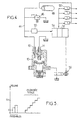
- FIG 4 shows, by way of example, a system injection using a pump of the kind shown in Figure 1 (only one module being shown.
- the discharge nozzle 16 is connected to a distribution ramp 44 fitted with a valve 46 overpressure safety and accumulator 48.
- the distribution ramp supplies the injectors 50, of which opening in sequence is caused by a generator electric pulse 52 controlled by a computer 54, in which is loaded a software fixing the strategy of piloting of injectors and pump.
- the calculator 54 can have a classic general constitution. He receives signals representative of the operating parameters engine position (throttle position, angular position of the flywheel, exhaust composition, etc.) as well as the output signal from a pressure sensor 55 which prevails in the distribution ramp 44.
- the computer deduces from this data the flow to be supplied by the pump and controls the solenoid valve 56 accordingly. Piloting the solenoid valve 56 by the management computer 54 can occur at a frequency much lower than the frequency pump actuation. Because the flow is controlled by adjusting the effective displacement of the membrane, therefore the volume driven back and forth from piston, there is no pressure drop comparable to that caused by a rolling of the fuel on a back to the tank.
- the pump will consist of several sets or modules, i.e. will have a constitution of the kind shown in Figures 2 and 3. Each set will have its own solenoid valve 56 or its own distributor, and may be ordered all or nothing.
- the sets or modules advantageously have 28 compartments and 12 different chambers.
- the pistons different sets can have diameters different and in particular contact surfaces with the liquid varying in geometric progression.
- a difference between membrane surfaces provides different flow rates for the same cam rotation speed and for the same piston stroke, simply by connecting one or more of the compartments at the landfill.
Landscapes
- Engineering & Computer Science (AREA)
- Mechanical Engineering (AREA)
- General Engineering & Computer Science (AREA)
- Chemical & Material Sciences (AREA)
- Combustion & Propulsion (AREA)
- Fuel-Injection Apparatus (AREA)
- Reciprocating Pumps (AREA)
Description
- la figure 1 est une vue schématique en coupe de la partie hydraulique ensemble ou module de pompe ;
- la figure 2 est une vue en coupe partielle d'une pompe comprenant plusieurs ensembles reliés à une alimentation et à une rampe de distribution commune ;
- la figure 3 est une vue de dessus schématique de la figure 2 ;
- la figure 4 est un schéma d'ensemble d'un système d'injection comportant une pompe du genre montré en figure 1 ;
- la figure 5 montre une répartition possible des cylindrées de plusieurs ensembles appartenant à une même pompe.
Claims (8)
- Pompe d'injection comprenant, dans un boítier (10), plusieurs modules ayant chacun au moins une chambre (12) d'alimentation d'un circuit d'injection, séparée par une membrane déformable (18) d'un compartiment (26) délimité par un alésage (28) du boítier et par un piston (30) animé d'un mouvement de va et vient, ladite chambre (12) étant reliée à une alimentation en carburant et au circuit d'injection par des clapets anti-retour respectifs, des moyens étant prévus pour ajuster indépendamment la pression du liquide qui occupe chaque compartiment (26), tous les pistons étant commandés par un même organe.
- Pompe selon la revendication 1, caractérisée en ce que chaque compartiment est relié à une admission de fluide hydraulique par l'intermédiaire d'un clapet anti-retour (34) et à une électrovanne (56) d'isolement du compartiment et de décharge.
- Pompe selon la revendication 1 ou 2, caractérisée en ce que la chambre (12) contient une coupelle (20) repoussée par un ressort (24) vers la membrane, munie de moyens limitant les déplacements qu'elle impose à la membrane.
- Pompe selon la revendication 1, 2 ou 3, caractérisée en ce que toutes les chambres d'alimentation (12) sont reliées entre elles.
- Pompe selon la revendication 4, caractérisée en ce que les pistons (30) des différents modules ont des diamètres différents.
- Pompe selon la revendication 5, caractérisée en ce que les pistons ont des surfaces de contact avec le liquide variant en progression géométrique.
- Système d'injection de combustible pour moteur à allumage commandé, comprenant une pompe selon la revendication 1 ou 2, caractérisée en ce que les moyens d'ajustement de la pression sont prévus pour à volonté relier chaque compartiment à une bâche de décharge ou l'en séparer.
- Système selon la revendication 7, caractérisé en ce que lesdits moyens comprennent une électrovanne (36) par compartiment.
Applications Claiming Priority (3)
| Application Number | Priority Date | Filing Date | Title |
|---|---|---|---|
| FR9708595A FR2765635B1 (fr) | 1997-07-07 | 1997-07-07 | Pompe d'injection directe de combustible pour moteur a allumage commande et systeme d'injection comportant une telle pompe |
| FR9708595 | 1997-07-07 | ||
| PCT/FR1998/001451 WO1999002851A1 (fr) | 1997-07-07 | 1998-07-07 | Pompe d'injection directe de combustible pour moteur a allumage commande et systeme d'injection comportant une telle pompe |
Publications (2)
| Publication Number | Publication Date |
|---|---|
| EP0995030A1 EP0995030A1 (fr) | 2000-04-26 |
| EP0995030B1 true EP0995030B1 (fr) | 2002-03-27 |
Family
ID=9508951
Family Applications (1)
| Application Number | Title | Priority Date | Filing Date |
|---|---|---|---|
| EP98936458A Expired - Lifetime EP0995030B1 (fr) | 1997-07-07 | 1998-07-07 | Pompe d'injection directe de combustible pour moteur a allumage commande et systeme d'injection comportant une telle pompe |
Country Status (6)
| Country | Link |
|---|---|
| US (1) | US6178951B1 (fr) |
| EP (1) | EP0995030B1 (fr) |
| JP (1) | JP2002508047A (fr) |
| DE (1) | DE69804460T2 (fr) |
| FR (1) | FR2765635B1 (fr) |
| WO (1) | WO1999002851A1 (fr) |
Families Citing this family (10)
| Publication number | Priority date | Publication date | Assignee | Title |
|---|---|---|---|---|
| FR2826068B1 (fr) * | 2001-06-19 | 2004-02-13 | Siemens Automotive Hydraulics | Dispositif de regulation de debit pour pompe transfert a carburant |
| FR2832492B1 (fr) * | 2001-11-20 | 2004-02-06 | Snecma Moteurs | Perfectionnements apportes aux injecteurs de turbomachine |
| AU2003246384A1 (en) * | 2003-07-04 | 2005-01-28 | Leslie James Warren | Liquid pump and method for pumping a liquid that may have gas coming out of solution |
| US7290561B2 (en) * | 2004-12-16 | 2007-11-06 | Diversified Dynamics Corporation | Pulsation causing valve for a plural piston pump |
| US7278443B2 (en) * | 2004-12-16 | 2007-10-09 | Diversified Dynamics Corporation | Pulsation causing valve for a plural piston pump |
| US20060140778A1 (en) * | 2004-12-28 | 2006-06-29 | Warren Leslie J | Reciprocating positive displacement pump for deionized water and method of cooling and lubricating therefor |
| US20060239834A1 (en) * | 2005-04-20 | 2006-10-26 | Larson Steve A | Metered pulse pump |
| US7552720B2 (en) * | 2007-11-20 | 2009-06-30 | Hitachi, Ltd | Fuel pump control for a direct injection internal combustion engine |
| JP5051279B2 (ja) * | 2009-12-21 | 2012-10-17 | 株式会社デンソー | 定残圧弁 |
| DE102010039831B4 (de) * | 2010-08-26 | 2022-02-03 | Prominent Gmbh | Membranpumpe sowie Verfahren zum Einstellen einer solchen |
Family Cites Families (12)
| Publication number | Priority date | Publication date | Assignee | Title |
|---|---|---|---|---|
| FR1038510A (fr) * | 1951-06-19 | 1953-09-29 | Pompe à injection pour carburant | |
| US2960936A (en) * | 1958-07-11 | 1960-11-22 | William M Dean | Fuel injection pump |
| FR1211846A (fr) * | 1958-10-18 | 1960-03-18 | Pompe hydraulique pour pulvérisateurs agricoles | |
| DE1528474B1 (de) * | 1966-03-01 | 1970-07-23 | Lewa Herbert Ott Fa | Hydraulische Steuereinrichtung an einer Membranpumpe |
| US3918846A (en) * | 1973-07-19 | 1975-11-11 | Lear Motors Corp | Vapor generator feedwater pump |
| US4501533A (en) * | 1979-11-15 | 1985-02-26 | Bower Jr Frank A | Apparatus for delivering liquid under pressure |
| DE3706697A1 (de) * | 1987-03-02 | 1988-09-15 | Breinlich Richard Dr | Hochdruckmembrane fuer grosse foerdermenge |
| US5249932A (en) * | 1991-10-07 | 1993-10-05 | Erik Van Bork | Apparatus for controlling diaphragm extension in a diaphragm metering pump |
| JPH062664A (ja) * | 1992-06-22 | 1994-01-11 | Nippon Soken Inc | ダイアフラム式ポンプ |
| JPH06173811A (ja) * | 1992-10-08 | 1994-06-21 | Nippon Soken Inc | 燃料噴射装置 |
| DE4327970C2 (de) * | 1993-08-19 | 1997-07-03 | Ott Kg Lewa | Hydraulisch angetriebene Membranpumpe mit mechanischer Membranhubbegrenzung |
| US6113361A (en) * | 1999-02-02 | 2000-09-05 | Stanadyne Automotive Corp. | Intensified high-pressure common-rail supply pump |
-
1997
- 1997-07-07 FR FR9708595A patent/FR2765635B1/fr not_active Expired - Lifetime
-
1998
- 1998-07-07 JP JP50824999A patent/JP2002508047A/ja active Pending
- 1998-07-07 WO PCT/FR1998/001451 patent/WO1999002851A1/fr not_active Ceased
- 1998-07-07 US US09/462,275 patent/US6178951B1/en not_active Expired - Lifetime
- 1998-07-07 DE DE69804460T patent/DE69804460T2/de not_active Expired - Lifetime
- 1998-07-07 EP EP98936458A patent/EP0995030B1/fr not_active Expired - Lifetime
Also Published As
| Publication number | Publication date |
|---|---|
| US6178951B1 (en) | 2001-01-30 |
| JP2002508047A (ja) | 2002-03-12 |
| WO1999002851A1 (fr) | 1999-01-21 |
| EP0995030A1 (fr) | 2000-04-26 |
| FR2765635B1 (fr) | 1999-09-03 |
| DE69804460D1 (de) | 2002-05-02 |
| FR2765635A1 (fr) | 1999-01-08 |
| DE69804460T2 (de) | 2002-11-14 |
Similar Documents
| Publication | Publication Date | Title |
|---|---|---|
| EP0980466B1 (fr) | Dispositif permettant de faire varier la cylindree et/ou le rapport volumetrique effectifs d'un moteur a pistons pendant son fonctionnement | |
| CA2692703C (fr) | Centrale hydraulique pour moteur a taux de compression variable | |
| EP0407436B1 (fr) | Groupe motopropulseur, notamment pour vehicule automobile et vehicule comportant un tel groupe | |
| US5772413A (en) | Bellows type pump | |
| JPH10503823A (ja) | 間欠作動式トランスファーポンプを有する往復動型の燃料ポンプ | |
| EP0995030A1 (fr) | Pompe d'injection directe de combustible pour moteur a allumage commande et systeme d'injection comportant une telle pompe | |
| US6210127B1 (en) | Fuel pump | |
| FR2805857A1 (fr) | Pompe d'alimentation d'un systeme d'injection de carburant et d'une commande hydraulique de soupape d'un moteur a combustion interne | |
| JPS6090980A (ja) | ユニツト燃料インジエクタ | |
| JP2020133506A (ja) | 燃料噴射ポンプ | |
| US6622706B2 (en) | Pump, pump components and method | |
| GB2178112A (en) | Distributor-type injection pump for an internal combustion engine | |
| FR2659116A1 (fr) | Compresseur multi-etages de volume variable autolubrifiant. | |
| FR2498686A1 (fr) | Dispositif d'alimentation en carburant d'un moteur a combustion interne | |
| US4788959A (en) | Fuel injection pump | |
| EP0731886A1 (fr) | Dispositif de lubrification d'un assemblage entre deux pieces mecaniques mobiles l'une par rapport a l'autre, notamment articulation bielle-piston | |
| FR2711433A1 (fr) | Régulateur coaxial de débit. | |
| FR2515256A1 (fr) | Pompe mixte a carburant et huile actionnee par pression | |
| FR2586758A1 (fr) | Injecteur de carburant et installation d'injection de carburant | |
| EP4709982A1 (fr) | Adaptateur de pression ameliore pour systeme hydraulique | |
| WO2024231634A1 (fr) | Adaptateur de pression ameliore pour systeme hydraulique | |
| WO2024231637A1 (fr) | Adaptateur de pression ameliore pour systeme hydraulique | |
| WO1999036686A1 (fr) | Pompe hydraulique a palier d'entrainement monte sur un moteur | |
| EP4709983A1 (fr) | Machine hydraulique multi cylindrees amelioree | |
| JP3981484B2 (ja) | 燃料噴射ポンプの脈動圧低減構造 |
Legal Events
| Date | Code | Title | Description |
|---|---|---|---|
| PUAI | Public reference made under article 153(3) epc to a published international application that has entered the european phase |
Free format text: ORIGINAL CODE: 0009012 |
|
| 17P | Request for examination filed |
Effective date: 20000113 |
|
| AK | Designated contracting states |
Kind code of ref document: A1 Designated state(s): DE IT |
|
| GRAG | Despatch of communication of intention to grant |
Free format text: ORIGINAL CODE: EPIDOS AGRA |
|
| 17Q | First examination report despatched |
Effective date: 20010704 |
|
| GRAG | Despatch of communication of intention to grant |
Free format text: ORIGINAL CODE: EPIDOS AGRA |
|
| GRAH | Despatch of communication of intention to grant a patent |
Free format text: ORIGINAL CODE: EPIDOS IGRA |
|
| GRAH | Despatch of communication of intention to grant a patent |
Free format text: ORIGINAL CODE: EPIDOS IGRA |
|
| GRAA | (expected) grant |
Free format text: ORIGINAL CODE: 0009210 |
|
| AK | Designated contracting states |
Kind code of ref document: B1 Designated state(s): DE IT |
|
| REF | Corresponds to: |
Ref document number: 69804460 Country of ref document: DE Date of ref document: 20020502 |
|
| PLBE | No opposition filed within time limit |
Free format text: ORIGINAL CODE: 0009261 |
|
| STAA | Information on the status of an ep patent application or granted ep patent |
Free format text: STATUS: NO OPPOSITION FILED WITHIN TIME LIMIT |
|
| 26N | No opposition filed |
Effective date: 20021230 |
|
| PGFP | Annual fee paid to national office [announced via postgrant information from national office to epo] |
Ref country code: DE Payment date: 20160719 Year of fee payment: 19 Ref country code: IT Payment date: 20160725 Year of fee payment: 19 |
|
| REG | Reference to a national code |
Ref country code: DE Ref legal event code: R119 Ref document number: 69804460 Country of ref document: DE |
|
| PG25 | Lapsed in a contracting state [announced via postgrant information from national office to epo] |
Ref country code: DE Free format text: LAPSE BECAUSE OF NON-PAYMENT OF DUE FEES Effective date: 20180201 |
|
| PG25 | Lapsed in a contracting state [announced via postgrant information from national office to epo] |
Ref country code: IT Free format text: LAPSE BECAUSE OF NON-PAYMENT OF DUE FEES Effective date: 20170707 |