EP0995023B1 - Power control circuit for electromagnetic actuator such as an injector or an electrovalve - Google Patents
Power control circuit for electromagnetic actuator such as an injector or an electrovalve Download PDFInfo
- Publication number
- EP0995023B1 EP0995023B1 EP98936459A EP98936459A EP0995023B1 EP 0995023 B1 EP0995023 B1 EP 0995023B1 EP 98936459 A EP98936459 A EP 98936459A EP 98936459 A EP98936459 A EP 98936459A EP 0995023 B1 EP0995023 B1 EP 0995023B1
- Authority
- EP
- European Patent Office
- Prior art keywords
- coil
- switching means
- capacitor
- actuating
- closure
- Prior art date
- Legal status (The legal status is an assumption and is not a legal conclusion. Google has not performed a legal analysis and makes no representation as to the accuracy of the status listed.)
- Expired - Lifetime
Links
Images


Classifications
-
- F—MECHANICAL ENGINEERING; LIGHTING; HEATING; WEAPONS; BLASTING
- F02—COMBUSTION ENGINES; HOT-GAS OR COMBUSTION-PRODUCT ENGINE PLANTS
- F02D—CONTROLLING COMBUSTION ENGINES
- F02D41/00—Electrical control of supply of combustible mixture or its constituents
- F02D41/20—Output circuits, e.g. for controlling currents in command coils
-
- H—ELECTRICITY
- H01—ELECTRIC ELEMENTS
- H01F—MAGNETS; INDUCTANCES; TRANSFORMERS; SELECTION OF MATERIALS FOR THEIR MAGNETIC PROPERTIES
- H01F7/00—Magnets
- H01F7/06—Electromagnets; Actuators including electromagnets
- H01F7/08—Electromagnets; Actuators including electromagnets with armatures
- H01F7/18—Circuit arrangements for obtaining desired operating characteristics, e.g. for slow operation, for sequential energisation of windings, for high-speed energisation of windings
- H01F7/1805—Circuit arrangements for holding the operation of electromagnets or for holding the armature in attracted position with reduced energising current
- H01F7/1816—Circuit arrangements for holding the operation of electromagnets or for holding the armature in attracted position with reduced energising current making use of an energy accumulator
-
- F—MECHANICAL ENGINEERING; LIGHTING; HEATING; WEAPONS; BLASTING
- F02—COMBUSTION ENGINES; HOT-GAS OR COMBUSTION-PRODUCT ENGINE PLANTS
- F02D—CONTROLLING COMBUSTION ENGINES
- F02D41/00—Electrical control of supply of combustible mixture or its constituents
- F02D41/20—Output circuits, e.g. for controlling currents in command coils
- F02D2041/2003—Output circuits, e.g. for controlling currents in command coils using means for creating a boost voltage, i.e. generation or use of a voltage higher than the battery voltage, e.g. to speed up injector opening
- F02D2041/2006—Output circuits, e.g. for controlling currents in command coils using means for creating a boost voltage, i.e. generation or use of a voltage higher than the battery voltage, e.g. to speed up injector opening by using a boost capacitor
-
- F—MECHANICAL ENGINEERING; LIGHTING; HEATING; WEAPONS; BLASTING
- F02—COMBUSTION ENGINES; HOT-GAS OR COMBUSTION-PRODUCT ENGINE PLANTS
- F02D—CONTROLLING COMBUSTION ENGINES
- F02D41/00—Electrical control of supply of combustible mixture or its constituents
- F02D41/20—Output circuits, e.g. for controlling currents in command coils
- F02D2041/2003—Output circuits, e.g. for controlling currents in command coils using means for creating a boost voltage, i.e. generation or use of a voltage higher than the battery voltage, e.g. to speed up injector opening
- F02D2041/201—Output circuits, e.g. for controlling currents in command coils using means for creating a boost voltage, i.e. generation or use of a voltage higher than the battery voltage, e.g. to speed up injector opening by using a boost inductance
-
- F—MECHANICAL ENGINEERING; LIGHTING; HEATING; WEAPONS; BLASTING
- F02—COMBUSTION ENGINES; HOT-GAS OR COMBUSTION-PRODUCT ENGINE PLANTS
- F02D—CONTROLLING COMBUSTION ENGINES
- F02D41/00—Electrical control of supply of combustible mixture or its constituents
- F02D41/20—Output circuits, e.g. for controlling currents in command coils
- F02D2041/2003—Output circuits, e.g. for controlling currents in command coils using means for creating a boost voltage, i.e. generation or use of a voltage higher than the battery voltage, e.g. to speed up injector opening
- F02D2041/2013—Output circuits, e.g. for controlling currents in command coils using means for creating a boost voltage, i.e. generation or use of a voltage higher than the battery voltage, e.g. to speed up injector opening by using a boost voltage source
-
- F—MECHANICAL ENGINEERING; LIGHTING; HEATING; WEAPONS; BLASTING
- F02—COMBUSTION ENGINES; HOT-GAS OR COMBUSTION-PRODUCT ENGINE PLANTS
- F02D—CONTROLLING COMBUSTION ENGINES
- F02D41/00—Electrical control of supply of combustible mixture or its constituents
- F02D41/20—Output circuits, e.g. for controlling currents in command coils
- F02D2041/202—Output circuits, e.g. for controlling currents in command coils characterised by the control of the circuit
- F02D2041/2024—Output circuits, e.g. for controlling currents in command coils characterised by the control of the circuit the control switching a load after time-on and time-off pulses
- F02D2041/2027—Control of the current by pulse width modulation or duty cycle control
-
- F—MECHANICAL ENGINEERING; LIGHTING; HEATING; WEAPONS; BLASTING
- F02—COMBUSTION ENGINES; HOT-GAS OR COMBUSTION-PRODUCT ENGINE PLANTS
- F02D—CONTROLLING COMBUSTION ENGINES
- F02D41/00—Electrical control of supply of combustible mixture or its constituents
- F02D41/30—Controlling fuel injection
- F02D41/38—Controlling fuel injection of the high pressure type
- F02D2041/389—Controlling fuel injection of the high pressure type for injecting directly into the cylinder
-
- H—ELECTRICITY
- H01—ELECTRIC ELEMENTS
- H01F—MAGNETS; INDUCTANCES; TRANSFORMERS; SELECTION OF MATERIALS FOR THEIR MAGNETIC PROPERTIES
- H01F7/00—Magnets
- H01F7/06—Electromagnets; Actuators including electromagnets
- H01F7/08—Electromagnets; Actuators including electromagnets with armatures
- H01F7/18—Circuit arrangements for obtaining desired operating characteristics, e.g. for slow operation, for sequential energisation of windings, for high-speed energisation of windings
- H01F7/1805—Circuit arrangements for holding the operation of electromagnets or for holding the armature in attracted position with reduced energising current
- H01F7/1816—Circuit arrangements for holding the operation of electromagnets or for holding the armature in attracted position with reduced energising current making use of an energy accumulator
- H01F2007/1822—Circuit arrangements for holding the operation of electromagnets or for holding the armature in attracted position with reduced energising current making use of an energy accumulator using a capacitor to produce a boost voltage
Definitions
- the invention relates to a circuit for controlling power, for the power supply of a actuating coil of at least one electromagnetic actuator, such as a solenoid valve or a fuel, in particular for internal combustion engine direct injection.
- injectors have a very short response time to both opening and closing, so that the durations of the fuel injection phases by the injectors correspond as precisely as possible to the durations calculated by an electronic control unit and calculation, commonly called engine control computer, which notably controls the injection of fuel, and, if necessary ignition, if necessary, from operating parameters engine speed, such as engine speed, pressure of air to the intake manifold, temperature of the engine cooling, oxygen content in gases which are detected by appropriate detectors.
- engine control computer which notably controls the injection of fuel, and, if necessary ignition, if necessary, from operating parameters engine speed, such as engine speed, pressure of air to the intake manifold, temperature of the engine cooling, oxygen content in gases which are detected by appropriate detectors.
- electromagnetic injectors are open by the power supply electric from their actuating coil so as to develop a sufficiently intense electromagnetic force on a movable member of the injector, called needle, to spread it, against return springs, against a seat which it is kept applied with sealing by said springs in the closed position.
- FR-A-2 538 942 EP-A-0 548 915 and FR-A-2 735 591 of power control circuits, for power supply electric of an actuating coil of at least one electromagnetic actuator, such as a fuel
- circuits including an accumulation stage or booster, connected to a power source direct current at low voltage, such as motor vehicle battery, and comprising a capacitor of energy accumulation, a self induction coil for the accumulation of energy, and of the first means switches, cyclically controlled at closing and at opening by a switching control unit, for ensure in succession at least two consistent sequences each to charge the self induction coil from said power source and then charging the capacitor from the self induction coil and through a diode, and second switching means, controlled by the closing by said control unit to ensure supply of said actuating coil by discharge of said capacitor, to also obtain the establishment fast of a high inrush current.
- the actuating coil of the electromagnetic actuator directly as a coil self induction for energy accumulation in the floor booster, to simplify the implementation and reduce the cost of such power control circuits.
- the problem underlying the invention is to perfect these power control circuits known from so that their energy storage stage can store then discharge more energy than known circuits to be able to actuate electromagnetic actuators requiring great control power, such as electro-magnetic injectors for direct injection of fuel in the combustion chambers of diesel engines or spark ignition engines, in which the injectors are supplied with high pressure fuel and are returned to the closed position by springs of powerful recall, without the control circuits of power of the invention to be much more complex nor much more expensive than known circuits.
- the power control circuit of the invention is characterized in that said self induction coil is separate from said actuation coil, and in that after charging the capacitor and before supplying said coil actuation, said switching control unit controls the closing of said first switching means to charge said self induction coil, so that the closure of said second switching means, said actuating coil is powered by simultaneous discharge of said capacitor and of said self induction coil.
- the circuit of power control of the invention is no more complex neither significantly more expensive, and essentially requires a modification of the control mode of the switching means which is provided by the switching control unit.
- This modification of the command mode is reduced to a modification control software when, advantageously, the switching means include electronic switches, in particular transistorized, controlled by a command logic delivered by the switching control unit, which includes at least one microprocessor or microcontroller.
- the circuit of the invention advantageously comprises in addition to the third switching means, interposed between the power source and the self induction coil, and orders; by the closing control unit for ensure the initial charges of the capacitor and the self induction coil, then after closing the second switching means, cyclically controlled at opening and closing to ensure in the coil actuation, a lower intensity holding current to that of the inrush current resulting from the discharge of the capacitor and the self induction coil.
- the self induction coil and the capacitor are used, as a first step, as reservoir, of energy, restored in a second time to provide high inrush current with rise time very fast, but the self induction coil and the capacitor can, in combination with the third means switches, used for the maintenance of a holding current, thanks to a DC converter structure in direct current which has the advantage of being of low radiation electro-magnetic, because it can work almost resonance, so that the power circuit of the invention can meet electromagnetic emission standards more stringent which will soon be in force, especially for on-board equipment on vehicles automobiles, such as solenoid valves and injectors, especially for direct fuel injection installation.
- third switching means it is possible after the closing of the second switch means controlling the simultaneous discharge of the capacitor and the inductor induction in the actuating coil, and before the holding current delivery, cyclic control the third switching means at the opening and at the closing by the switching control unit, so maintain the inrush current at an intensity close to that resulting from the simultaneous discharge of the capacitor and from the self induction coil to the actuation coil.
- This maintenance phase of the inrush current at a level high can thus take place between the initial phase quick establishment of inrush current and phase setting the holding current at a lower level intensity.
- the third switching means are advantageously controlled by the control unit with a variable opening duty cycle to ensure holding current and / or maintaining the inrush current.
- the second switching means are controlled at opening by the control unit, preferably when the actuating coil is traversed by the holding current, so as to quickly cancel the current in this coil, to obtain a brief cut of the current, necessary to obtain good accuracy of actuator operation.
- the circuit of the invention is also advantageous by the fact that the booster stage can supply in parallel the actuating coils of at least two actuators electromagnetic, and in particular the coils of all the injectors of an internal combustion engine.
- the second and third switching means can be ordered at closing to obtain a recovery of at least two feed times actuating coils, which allows recoveries to be managed injection duration, with a single power circuit, in the case of applications to injection engines.
- the third means switches and the self induction coil form a converter which advantageously ensures an increase holding current during these recoveries.
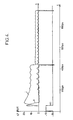
- the power control circuit of Figure 1 includes a self induction coil 1 connected by a end in series with a switch 2 connected to the terminal "+" from a DC power source 3 at low voltage Vbat, which is the battery of a motor vehicle, whose terminal "-" is earthed.
- coil 1 is connected in parallel to another switch 4, connected to ground, and via a diode 5, on the one hand to a terminal of a capacitor 6, whose other terminal is connected to ground, and, on the other hand, with four actuator actuator coils 7, 8, 9 and 10, which are connected in parallel with each other, and each of which is connected to ground via one respectively of four power switches 11, 12, 13 and 14, the overvoltage at the terminals of each coil of injector 7 to 10 being limited, for example to around 80V, by a Zenner diode 15 in parallel on the switch 11, 12, 13 or 14 corresponding.
- a capacitor 17, with a value of about 0.5 ⁇ F at about 5 ⁇ F, and a reverse diode 18 are each mounted in parallel on switch 2, and diode 18 can be the diode integrated in a MOS type switching transistor channel P constituting the switch 2.
- a diode reverse 19 is connected in parallel on switch 4, and this diode can be the integrated diode of a transistor N-type MOS switching device constituting the switch 4.
- All switches 2, 4, 11, 12, 13 and 14 are solid state electronic switches controlled by opening and closing by control signals low and high level logic delivered by a unit of switching logic control 16 with microprocessors or microcontrollers, and which is connected to each of the switches ordered through a command line.
- Coil 1 for example having a coefficient self-induction from about 10 ⁇ H to about 50 ⁇ H, is a energy storage coil.
- the capacitor 6, by example with a capacity between 1 and 10 ⁇ F, is a capacitor of a technology other than chemical, of preferably for storing capacitive energy and for ensure energy transfer from the self induction coil 1 to at least one injector coil 7 to 10.
- Switch 4 is cyclically controlled at the closing and opening by unit 16 to ensure, when switch 2 is closed, the coil load 1, for a time varying from approximately 20 ⁇ s to approximately 100 ⁇ s, when switch 4 is closed, then to ensure the charging of the capacitor 6 through the diode 5, by transfer of inductive energy from coil 1, when switch 4 is open.
- Switch 2 is also ordered to close by unit 16 during a time from about 10 ⁇ s to about 70 ⁇ s, to ensure the load of coil 1, then in a later phase explained below, switch 2 is controlled so cyclic at closing and opening by unit 16 for maintain the current at a determined value, about 3 to 5 A, in at least one of the injector coils 7 to 10 supplied by closing the switch 11 to 14 correspondent. Indeed, each of the switches 11 to 14 is intended to ensure the conduction of the coil of injector 7 to 10 corresponding.
- Diode 5 is for function of avoiding the discharge of the capacitor 6 by the switches 2 and 4 when closed.
- the circuit operation sequencing, controlled by unit 16 is as follows: closing switches 2 and 4 causes the load of the coil 1, traversed by a current iL which increases linearly from 0 to about 15 A for a time of about 20 ⁇ s to about 100 ⁇ s.
- the opening switch 4 causes the capacitor 6 to charge by energy transfer from coil 1 to the capacitor 6, through diode 5.
- the voltage across the capacitor 6 grows along an exponential curve, at the same time that a current peak occurs.
- This sequence comprising a charge of coil 1 followed by a charge of capacitor 6 is renewed a certain number of times up to charge capacitor 6 at a voltage of 80 V about.
- one of the injector switches by example switch 11 is closed, while switch 2 remains closed and switch 4 is open (see Figures 3 and 4), so that a simultaneous discharge of coil 1 and capacitor 6 into the coil injector 7, traversed by an intense inrush current, which reaches 15 to 20 A after a time of 30 to 50 ⁇ s, and corresponds to the sum of the currents resulting from the discharge capacitive of capacitor 6 and the inductive discharge of coil 1.
- an intense inrush current which reaches 15 to 20 A after a time of 30 to 50 ⁇ s, and corresponds to the sum of the currents resulting from the discharge capacitive of capacitor 6 and the inductive discharge of coil 1.
- the control unit 16 cyclically controls the switch 2 with a variable aperture duty cycle, which is then lowered to decrease the current to an intensity of 3 to 5 A approximately, then keep it around this value to ensure a holding current of the injector in its coil 7.
- the booster stage comprising the coil 1, the diode 5, the switch 4 and the capacitor 6, supplies parallel the injector coils 7 to 10.
- Switch 2 and the two switches for example 11 and 12 of the two injector coils 7 and 8 to be supplied with recovery are controlled upon opening by the control unit 16 of so as to ensure this recovery of feeding times.
- Curves (a) and (b) in Figure 6 show the currents i1 and i2 in the injector coils 7 and 8 after the two time-shifted switch 4 closures - see curve (d) - to load coil 1 just before shifted closings of switches 11 and 12, which are at the origin of currents i1 and 12.
- the charges of coil 1 resulting from the closings of switch 4 are visible on the curve (c) of figure 6, representing the current iL in this coil 1.
- the switch 2 command with a variable duty cycle after the openings of the switch 4 allows maintaining the inrush current then obtaining the inrush current maintenance.
Landscapes
- Engineering & Computer Science (AREA)
- Physics & Mathematics (AREA)
- Electromagnetism (AREA)
- Power Engineering (AREA)
- Chemical & Material Sciences (AREA)
- Combustion & Propulsion (AREA)
- Mechanical Engineering (AREA)
- General Engineering & Computer Science (AREA)
- Electrical Control Of Air Or Fuel Supplied To Internal-Combustion Engine (AREA)
- Fuel-Injection Apparatus (AREA)
Abstract
Description
L'invention concerne un circuit de commande de puissance, pour l'alimentation en courant électrique d'une bobine d'actionnement d'au moins un actionneur électro-magnétique, tel qu'une électrovanne ou un injecteur de carburant, en particulier pour moteur à combustion interne à injection directe.The invention relates to a circuit for controlling power, for the power supply of a actuating coil of at least one electromagnetic actuator, such as a solenoid valve or a fuel, in particular for internal combustion engine direct injection.
Il est connu que certains actionneurs électro-magnétiques, tels que les électrovannes, notamment pour les installations de recirculation des gaz d'échappement de moteur à combustion interne de véhicules automobiles, et les injecteurs de carburant de moteurs à combustion interne, comprennent des bobines ou enroulements d'actionnements devant être alimentés par des courants d'appel de forte intensité, à établissement et à coupure rapides, afin d'obtenir des durées d'actionnement précises, en particulier des durées précises d'injection de carburant par des injecteurs.It is known that certain electromagnetic actuators, such as solenoid valves, especially for exhaust gas recirculation systems internal combustion engine of motor vehicles, and fuel injectors for internal combustion engines, include actuator coils or windings to be supplied by strong inrush currents intensity, quick set-up and shutdown, so obtain precise actuation times, in particular specific times of fuel injection by injectors.
En effet, le bon fonctionnement d'un moteur à injection, aux plans tout à la fois de la puissance délivrée, de la pollution et de la consommation, suppose que les injecteurs présentent un temps de réponse très court à l'ouverture comme à la fermeture, afin que les durées effectives des phases d'injection de carburant par les injecteurs correspondent aussi précisément que possible aux durées calculées par une unité électronique de commande et calcul, communément appelée calculateur de contrôle moteur, qui commande notamment l'injection du carburant, et, le cas échéant, l'allumage à partir de paramètres de fonctionnement du moteur, tels que régime de rotation du moteur, pression d'air au collecteur d'admission, température du fluide de refroidissement du moteur, teneur en oxygène dans les gaz d'échappement, qui sont détectés par des détecteurs appropriés. Indeed, the proper functioning of an engine injection, at the same time of the power delivered, pollution and consumption, assumes that injectors have a very short response time to both opening and closing, so that the durations of the fuel injection phases by the injectors correspond as precisely as possible to the durations calculated by an electronic control unit and calculation, commonly called engine control computer, which notably controls the injection of fuel, and, if necessary ignition, if necessary, from operating parameters engine speed, such as engine speed, pressure of air to the intake manifold, temperature of the engine cooling, oxygen content in gases which are detected by appropriate detectors.
Il est de plus connu que les injecteurs électro-magnétiques sont ouverts par l'alimentation en courant électrique de leur bobine d'actionnement de sorte à développer une force électro-magnétique suffisamment intense sur un organe mobile de l'injecteur, appelé aiguille, pour l'écarter, à l'encontre de ressorts de rappel, d'un siège contre lequel il est maintenu appliqué avec étanchéité par lesdits ressorts en position de fermeture.It is moreover known that electromagnetic injectors are open by the power supply electric from their actuating coil so as to develop a sufficiently intense electromagnetic force on a movable member of the injector, called needle, to spread it, against return springs, against a seat which it is kept applied with sealing by said springs in the closed position.
Pour obtenir un actionnement rapide, en particulier à l'ouverture, d'un injecteur sous une tension d'alimentation de sa bobine d'actionnement que cette dernière ne supporterait pas en permanence comme étant bien supérieure à la tension d'alimentation normale de cette bobine à partir d'une source d'alimentation conventionnelle à basse tension et à courant continu, telle qu'une batterie de véhicule automobile, et alors que la tension d'alimentation normale doit suffire à assurer le maintien de l'injecteur dans son état d'ouverture après une ouverture rapide initiale, il a déjà été proposé d'associer à la commande d'un injecteur électromagnétique un étage d'accumulation d'énergie, qui est soumis à des moyens de commande de décharge en phase initiale d'alimentation de la bobine d'actionnement de chaque injecteur considéré, afin d'obtenir, dans cette phase initiale, un courant d'appel élevé, capable d'assurer une ouverture rapide de l'injecteur, puis, dans une phase ultérieure, un courant de maintien d'intensité réduite par rapport à celle du courant d'appel, et permettant de maintenir l'injecteur ouvert par l'alimentation de sa bobine d'actionnement.To obtain rapid actuation, in particular at the opening, of an injector under a supply voltage of its actuating coil that the latter does not not endure permanently as being far superior at the normal supply voltage of this coil from a conventional low voltage power source and direct current, such as a vehicle battery automotive, and while the normal supply voltage must be sufficient to maintain the injector in its opening state after initial quick opening it has already proposed to associate with the order of an injector electromagnetic an energy accumulation stage, which is subject to phase discharge control means initial supply of the actuation coil each injector considered, in order to obtain, in this phase initial, a high inrush current, capable of ensuring a rapid opening of the injector, then, in a phase subsequent, a holding current of reduced intensity by compared to that of the inrush current, and allowing keep the injector open by feeding its coil actuating.
Par FR-A-2 425 137, on a proposé un tel circuit de commande de puissance avec étage d'accumulation d'énergie par charge d'une bobine de self induction raccordée à la source d'alimentation à basse tension et associée à des premiers moyens commutateurs commandés à la fermeture pour charger la bobine de self induction, puis à l'ouverture en même temps que des seconds moyens commutateurs, associés à la bobine d'actionnement de l'actionneur électro-magnétique et préalablement ouverts sont commandés à la fermeture, pour décharger la bobine de self induction dans la bobine d'actionnement et obtenir dans cette dernière l'établissement rapide d'un courant d'appel élevé.By FR-A-2 425 137, such a circuit has been proposed. power control with energy storage stage by charging a self induction coil connected to the low voltage power source and associated with first switching means controlled upon closing for load the self induction coil, then at the opening at the same time as second switching means, associated with the actuating coil of the electromagnetic actuator and previously opened are ordered at closing, for discharge the self induction coil into the coil of actuation and obtain in the latter the establishment fast of a high inrush current.
Parallèlement aux circuits de commande de puissance à décharge selfique, il a été proposé des circuits analogues à décharge capacitive. En particulier, on connait par FR-A-2 538 942, EP-A-0 548 915 et FR-A-2 735 591 des circuits de commande de puissance, pour l'alimentation électrique d'une bobine d'actionnement d'au moins un actionneur électro-magnétique, tel qu'un injecteur de carburant, les circuits comprenant un étage d'accumulation d'énergie ou survolteur, connecté à une source d'alimentation en courant continu à basse tension, telle qu'une batterie de véhicule automobile, et comportant un condensateur d'accumulation d'énergie, une bobine de self induction pour l'accumulation d'énergie, et des premiers moyens commutateurs, commandés cycliquement à la fermeture et à l'ouverture par une unité de commande de commutation, pour assurer en succession au moins deux séquences consistant chacune à charger la bobine de self induction à partir de ladite source d'alimentation, puis à charger le condensateur à partir de la bobine de self induction et au travers d'une diode, et des deuxièmes moyens commutateurs, commandés à la fermeture par ladite unité de commande pour assurer une alimentation de ladite bobine d'actionnement par la décharge dudit condensateur, pour obtenir également l'établissement rapide d'un courant d'appel élevé.In addition to power control circuits with inductive discharge, similar circuits have been proposed capacitive discharge. In particular, we know by FR-A-2 538 942, EP-A-0 548 915 and FR-A-2 735 591 of power control circuits, for power supply electric of an actuating coil of at least one electromagnetic actuator, such as a fuel, circuits including an accumulation stage or booster, connected to a power source direct current at low voltage, such as motor vehicle battery, and comprising a capacitor of energy accumulation, a self induction coil for the accumulation of energy, and of the first means switches, cyclically controlled at closing and at opening by a switching control unit, for ensure in succession at least two consistent sequences each to charge the self induction coil from said power source and then charging the capacitor from the self induction coil and through a diode, and second switching means, controlled by the closing by said control unit to ensure supply of said actuating coil by discharge of said capacitor, to also obtain the establishment fast of a high inrush current.
Dans les circuits de commande de puissance à décharge capacitive décrits dans les trois documents de brevet précités, on utilise la bobine d'actionnement de l'actionneur électro-magnétique directement comme bobine de self induction pour l'accumulation d'énergie dans l'étage survolteur, afin de simplifier la réalisation et réduire le coût de tels circuits de commande de puissance. In power control circuits to capacitive discharge described in the three documents of aforementioned patent, the actuating coil of the electromagnetic actuator directly as a coil self induction for energy accumulation in the floor booster, to simplify the implementation and reduce the cost of such power control circuits.
Le problème à la base de l'invention est de perfectionner ces circuits de commande de puissance connus de sorte que leur étage d'accumulation d'énergie puisse stocker puis décharger davantage d'énergie que les circuits connus pour pouvoir actionner des actionneurs électro-magnétiques nécessitant une grande puissance de commande, tels que les injecteurs électro-magnétiques pour l'injection directe de carburant dans les chambres de combustion de moteurs diesel ou de moteurs à allumage commandé, dans lesquels les injecteurs sont alimentés en carburant à haute pression et sont rappelés en position de fermeture par des ressorts de rappel puissants, sans que les circuits de commande de puissance de l'invention soient beaucoup plus complexes ni beaucoup plus coûteux que les circuits connus.The problem underlying the invention is to perfect these power control circuits known from so that their energy storage stage can store then discharge more energy than known circuits to be able to actuate electromagnetic actuators requiring great control power, such as electro-magnetic injectors for direct injection of fuel in the combustion chambers of diesel engines or spark ignition engines, in which the injectors are supplied with high pressure fuel and are returned to the closed position by springs of powerful recall, without the control circuits of power of the invention to be much more complex nor much more expensive than known circuits.
A cet effet, le circuit de commande de puissance de l'invention, du type présenté ci-dessus et connu par les trois documents de brevet précités, se caractérise en ce que ladite bobine de self induction est distincte de ladite bobine d'actionnement, et en ce qu'après la charge du condensateur et avant l'alimentation de ladite bobine d'actionnement, ladite unité de commande de commutation commande la fermeture desdits premiers moyens commutateurs pour charger ladite bobine de self induction, de sorte qu'à la fermeture desdits deuxièmes moyens commutateurs, ladite bobine d'actionnement est alimentée par la décharge simultanée dudit condensateur et de ladite bobine de self induction.To this end, the power control circuit of the invention, of the type presented above and known by three aforementioned patent documents, is characterized in that said self induction coil is separate from said actuation coil, and in that after charging the capacitor and before supplying said coil actuation, said switching control unit controls the closing of said first switching means to charge said self induction coil, so that the closure of said second switching means, said actuating coil is powered by simultaneous discharge of said capacitor and of said self induction coil.
Le transfert à la bobine d'actionnement de l'énergie accumulées dans le condensateur et dans la bobine de self induction par des décharges capacitive et selfique simultanées permet la commande en courant de la bobine d'actionnement avec un courant pic élevé établi plus rapidement qu'avec les circuits de commande de puissance de l'état de la technique. Par rapport à ces derniers, le circuit de commande de puissance de l'invention n'est pas plus complexe ni sensiblement plus coûteux, et nécessite essentiellement une modification du mode de commande des moyens commutateurs qui est assuré par l'unité de commande de commutation. Cette modification du mode de commande se réduit à une modification d'un logiciel de commande lorsque, avantageusement, les moyens commutateurs comprennent des commutateurs électroniques, notamment transistorisés, pilotés par une commande logique délivrée par l'unité de commande de commutation, qui comprend au moins un microprocesseur ou microcontrôleur.Transfer to the energy actuation coil accumulated in the capacitor and in the inductor induction by simultaneous capacitive and inductive discharges allows current control of the actuating coil with a high peak current established faster that with the power control circuits of the state of the technique. Compared to these, the circuit of power control of the invention is no more complex neither significantly more expensive, and essentially requires a modification of the control mode of the switching means which is provided by the switching control unit. This modification of the command mode is reduced to a modification control software when, advantageously, the switching means include electronic switches, in particular transistorized, controlled by a command logic delivered by the switching control unit, which includes at least one microprocessor or microcontroller.
Le circuit de l'invention comprend avantageusement de plus des troisièmes moyens commutateurs, interposés entre la source'd'alimentation et la bobine de self induction, et commandés; par l'unité de commande à la fermeture pour assurer les charges initiales du condensateur et de la bobine de self induction, puis, après la fermeture des deuxièmes moyens commutateurs, commandés cycliquement à l'ouverture et à la fermeture pour assurer dans la bobine d'actionnement, un courant de maintien d'intensité inférieure à celle du courant d'appel résultant de la décharge simultanée du condensateur et de la bobine de self induction. Ainsi, non seulement la bobine de self induction et le condensateur sont utilisés, dans un premier temps, comme réservoir, d'énergie, restituée dans un second temps pour fournir un courant d'appel élevé avec un temps de montée très rapide, mais la bobine de self induction et le condensateur peuvent, en combinaison avec les troisièmes moyens commutateurs, servir à l'entretien d'un courant de maintien, grâce à une structure de convertisseur de courant continu en courant continu qui a l'avantage d'être à faible rayonnement électro-magnétique, car pouvant fonctionner en quasi résonnance, de sorte que le circuit de puissance de l'invention peut respecter les normes d'émission électro-magnétiques plus strictes qui seront prochainement en vigueur, notamment pour des équipements embarqués sur véhicules automobiles, tels qu'électrovannes et injecteurs, en particulier pour installation d'injection directe de carburant.The circuit of the invention advantageously comprises in addition to the third switching means, interposed between the power source and the self induction coil, and orders; by the closing control unit for ensure the initial charges of the capacitor and the self induction coil, then after closing the second switching means, cyclically controlled at opening and closing to ensure in the coil actuation, a lower intensity holding current to that of the inrush current resulting from the discharge of the capacitor and the self induction coil. Thus, not only the self induction coil and the capacitor are used, as a first step, as reservoir, of energy, restored in a second time to provide high inrush current with rise time very fast, but the self induction coil and the capacitor can, in combination with the third means switches, used for the maintenance of a holding current, thanks to a DC converter structure in direct current which has the advantage of being of low radiation electro-magnetic, because it can work almost resonance, so that the power circuit of the invention can meet electromagnetic emission standards more stringent which will soon be in force, especially for on-board equipment on vehicles automobiles, such as solenoid valves and injectors, especially for direct fuel injection installation.
Avantageusement de plus, grâce à la présence des troisièmes moyens commutateurs, il est possible, après la fermeture des deuxièmes moyens commutateurs commandant la décharge simultanée du condensateur et de la bobine de self induction dans la bobine d'actionnement, et avant la délivrance du courant de maintien, de commander cycliquement les troisièmes moyens commutateurs à l'ouverture et à la fermeture par l'unité de commande de commutation, de sorte à entretenir le courant d'appel à une intensité voisine de celle résultant de la décharge simultanée du condensateur et de la bobine de self induction dans la bobine d'actionnement. Cette phase d'entretien du courant d'appel à un niveau élevé peut ainsi se dérouler entre la phase initiale d'établissement rapide du courant d'appel et la phase d'établissement du courant de maintien à un niveau inférieur d'intensité.Advantageously, thanks to the presence of third switching means it is possible after the closing of the second switch means controlling the simultaneous discharge of the capacitor and the inductor induction in the actuating coil, and before the holding current delivery, cyclic control the third switching means at the opening and at the closing by the switching control unit, so maintain the inrush current at an intensity close to that resulting from the simultaneous discharge of the capacitor and from the self induction coil to the actuation coil. This maintenance phase of the inrush current at a level high can thus take place between the initial phase quick establishment of inrush current and phase setting the holding current at a lower level intensity.
A cet effet, les troisièmes moyens commutateurs sont avantageusement commandés par l'unité de commande avec un rapport cyclique d'ouverture variable pour assurer le courant de maintien et/ou entretenir le courant d'appel.To this end, the third switching means are advantageously controlled by the control unit with a variable opening duty cycle to ensure holding current and / or maintaining the inrush current.
En outre, les deuxièmes moyens commutateurs sont commandés à l'ouverture par l'unité de commande, de préférence lorsque la bobine d'actionnement est parcourue par le courant de maintien, de sorte à annuler rapidement le courant dans cette bobine, pour obtenir une coupure brève du courant, nécessaire à l'obtention d'une bonne précision de fonctionnement de l'actionneur.In addition, the second switching means are controlled at opening by the control unit, preferably when the actuating coil is traversed by the holding current, so as to quickly cancel the current in this coil, to obtain a brief cut of the current, necessary to obtain good accuracy of actuator operation.
Le circuit de l'invention est également avantageux par le fait que l'étage survolteur peut alimenter en parallèle les bobines d'actionnement d'au moins deux actionneurs électro-magnétiques, et en particulier les bobines de tous les injecteurs d'un moteur à combustion interne. A cet effet, les deuxièmes et troisièmes moyens commutateurs peuvent être commandés à la fermeture de façon à obtenir un recouvrement des durées d'alimentation d'au moins deux bobines d'actionnement, ce qui permet de gérer les recouvrements de durée d'injection, avec un seul circuit de puissance, dans le cas des applications aux moteurs à injection.The circuit of the invention is also advantageous by the fact that the booster stage can supply in parallel the actuating coils of at least two actuators electromagnetic, and in particular the coils of all the injectors of an internal combustion engine. In this effect, the second and third switching means can be ordered at closing to obtain a recovery of at least two feed times actuating coils, which allows recoveries to be managed injection duration, with a single power circuit, in the case of applications to injection engines.
Dans cette configuration de gestion du recouvrement des durées d'actionnement des actionneurs, les troisièmes moyens commutateurs et la bobine de self induction forment un convertisseur qui assure avantageusement une augmentation du courant de maintien pendant ces recouvrements.In this configuration of collection management actuator actuation times, the third means switches and the self induction coil form a converter which advantageously ensures an increase holding current during these recoveries.
D'autres avantages et caractéristiques de l'invention découleront de la description donnée ci-dessous, à titre non limitatif, d'un exemple de réalisation décrit en référence aux dessins annexés sur lesquels :
- la figure 1 est un schéma synoptique du circuit de l'invention pour l'alimentation en parallèle des bobines d'actionnement de quatre injecteurs d'un moteur à combustion interne de véhicule à injection directe,
- la figure 2 est un chronogramme représentant les évolutions de la tension Vout à la borne commune du condensateur et de la diode de charge et du courant iL de la bobine de self induction en fonction de la commande logique des premiers moyens commutateurs pendant la phase de charges successives du condensateur,
- la figure 3 est un chronogramme représentant schématiquement l'évolution du courant i dans une bobine d'injecteur et la commande logique des seconds et troisièmes moyens commutateurs pour l'entretien du courant d'appel puis l'obtention du courant de maintien, jusqu'à la coupure du courant dans cette bobine,
- la figure 4 représente des chronogrammes montrant en superposition l'évolution respectivement du courant i dans une bobine d'injecteur et de la tension V aux bornes de cette bobine, en fonction de la commande logique des premiers moyens commutateurs pendant la phase de décharge,
- la figure 5 représente l'évolution du courant iL dans la bobine de self induction pendant la décharge, et
- la figure 6 représente des chronogrammes montrant l'évolution des courants i1 et i2 dans le cas du recouvrement des alimentations de deux bobines d'injecteur, ainsi que le courant iL dans la bobine de self induction en fonction des commandes logiques des premiers et troisièmes moyens commutateurs en phase de recouvrement.
- FIG. 1 is a block diagram of the circuit of the invention for the parallel supply of the actuating coils of four injectors of an internal combustion engine of a direct injection vehicle,
- FIG. 2 is a timing diagram representing the changes in the voltage Vout at the common terminal of the capacitor and the charging diode and of the current iL of the self-induction coil as a function of the logic control of the first switching means during the charging phase of the capacitor,
- FIG. 3 is a timing diagram schematically representing the evolution of the current i in an injector coil and the logic control of the second and third switching means for maintaining the inrush current and then obtaining the holding current, up to when the current is cut in this coil,
- FIG. 4 represents timing diagrams showing in superposition the evolution respectively of the current i in an injector coil and of the voltage V at the terminals of this coil, as a function of the logic control of the first switching means during the discharge phase,
- FIG. 5 represents the evolution of the current iL in the self-induction coil during the discharge, and
- FIG. 6 represents timing diagrams showing the evolution of the currents i1 and i2 in the case of the overlapping of the supplies of two injector coils, as well as the current iL in the self-induction coil as a function of the logic commands of the first and third means switches in recovery phase.
Le circuit de commande de puissance de la figure 1
comprend une bobine de self induction 1 connectée par une
extrémité en série avec un commutateur 2 relié à la borne
"+" d'une source d'alimentation 3 en courant continu à basse
tension Vbat, qui est la batterie d'un véhicule automobile,
dont la borne "-" est mise à la masse. Par son autre
extrémité, la bobine 1 est connectée en parallèle à un autre
commutateur 4, relié à la masse, et, par l'intermédiaire
d'une diode 5, d'une part à une borne d'un condensateur 6,
dont l'autre borne est reliée à la masse, et, d'autre part,
à quatre bobines d'actionnement d'injecteurs 7, 8, 9 et 10,
qui sont branchées en parallèle les unes sur les autres, et
dont chacune est reliée à la masse par l'intermédiaire de
l'un respectivement de quatre commutateurs d'alimentation
11, 12, 13 et 14, la surtension aux bornes de chaque bobine
d'injecteur 7 à 10 étant limitée, par exemple à environ 80V,
par une diode Zenner 15 en parallèle sur le commutateur 11,
12, 13 ou 14 correspondant.The power control circuit of Figure 1
includes a self induction coil 1 connected by a
end in series with a
Un condensateur 17, d'une valeur d'environ 0,5 µF à
environ 5 µF, et une diode inverse 18 sont montés chacun en
parallèle sur le commutateur 2, et la diode 18 peut être la
diode intégrée à un transistor de commutation de type MOS
canal P constituant le commutateur 2. De même, une diode
inverse 19 est branchée en parallèle sur le commutateur 4,
et cette diode peut être la diode intégrée d'un transistor
de commutation de type MOS canal N constituant le commutateur
4.A
Tous les commutateurs 2, 4, 11, 12, 13 et 14 sont
des commutateurs électroniques transistorisés pilotés à
l'ouverture et à la fermeture par des signaux de commande
logiques de niveaux bas et haut délivrés par une unité de
commande logique de commutation 16 à microprocesseurs ou
microcontrôleurs, et qui est reliée à chacun des commutateurs
commandés par une ligne de commande.All
La bobine 1, ayant par exemple un coefficient d'auto-induction d'environ 10 µH à environ 50 µH, est une bobine d'accumulation d'énergie. Le condensateur 6, par exemple d'une capacité comprise entre 1 et 10 µF, est un condensateur d'une technologie autre que chimique, de préférence, pour stocker de l'énergie capacitive et pour assurer un transfert d'énergie de la bobine de self induction 1 vers au moins une bobine d'injecteur 7 à 10.Coil 1, for example having a coefficient self-induction from about 10 µH to about 50 µH, is a energy storage coil. The capacitor 6, by example with a capacity between 1 and 10 µF, is a capacitor of a technology other than chemical, of preferably for storing capacitive energy and for ensure energy transfer from the self induction coil 1 to at least one injector coil 7 to 10.
Le commutateur 4 est commandé de façon cyclique à la
fermeture et à l'ouverture par l'unité 16 pour assurer,
lorsque le commutateur 2 est fermé, la charge de la bobine
1, pendant un temps variant d'environ 20µs à environ 100µs,
lorsque le commutateur 4 est fermé, puis pour assurer la
charge du condensateur 6 au travers de la diode 5, par
transfert d'énergie inductive provenant de la bobine 1,
lorsque le commutateur 4 est ouvert. Le commutateur 2 est
également commandé à la fermeture par l'unité 16 pendant un
temps d'environ 10 µs à environ 70 µs, pour assurer la
charge de la bobine 1, puis, dans une phase ultérieure
expliquée ci-dessous, le commutateur 2 est commandé de façon
cyclique à la fermeture et à l'ouverture par l'unité 16 pour
assurer le maintien du courant à une valeur déterminée,
d'environ 3 à 5 A, dans l'une au moins des bobines d'injecteur
7 à 10 alimentées par la fermeture du commutateur 11 à
14 correspondant. En effet, chacun des commutateurs 11 à 14
est destiné à assurer la mise en conduction de la bobine
d'injecteur 7 à 10 correspondante. La diode 5 a pour
fonction d'éviter la décharge du condensateur 6 par les
commutateurs 2 et 4 lorsqu'ils sont fermés.
Tous les commutateurs 11 à 14 étant ouverts, le
séquencement de fonctionnement du circuit, commandé par
l'unité 16 est le suivant : la fermeture des commutateurs 2
et 4 entraíne la charge de la bobine 1, parcourue par un
courant iL qui croít linéairement de 0 à environ 15 A
pendant un temps d'environ 20 µs à environ 100 µs. L'ouverture
du commutateur 4 entraíne la charge du condensateur 6
par transfert d'énergie de la bobine 1 vers le condensateur
6, au travers de la diode 5. La tension aux bornes du
condensateur 6 croit selon une courbe exponentielle, en même
temps que se produit un pic de courant. Cette séquence
comprenant une charge de la bobine 1 suivie d'une charge du
condensateur 6 est renouvelée un certain nombre de fois
jusqu'à charger le condensateur 6 à une tension de 80 V
environ. Cette séquence de charges successives est représentée
sur la figure 2, dont les courbes (a) et (b) représentent
la tension Vout au point A du circuit de la figure 1,
qui est à la borne commune au condensateur 6 et à la diode
5, et le courant iL dans la bobine 1, en fonction de la
commande logique du commutateur 4 (courbe (c)), le commutateur
2 étant fermé et donc passant pendant cette phase. Le
circuit, dans lequel la bobine 1, le commutateur 4, la diode
5 et le condensateur 6 constituent un étage survolteur, est
ensuite en situation d'attente jusqu'à un instant précédent
la fermeture de l'un au moins des commutateurs 11 à 14 pour
alimenter au moins une bobine d'injecteur 7 à 10. Juste
avant la commande d'un injecteur, le commutateur 4 est
fermé, comme montré sur la figure 4, pour charger à nouveau
la bobines 1. Puis l'un des commutateurs d'injecteur, par
exemple le commutateur 11, est fermé, alors que le commutateur
2 reste fermé et que le commutateur 4 est ouvert (voir
figures 3 et 4), de sorte qu'il se produit simultanément une
décharge de la bobine 1 et du condensateur 6 dans la bobine
d'injecteur 7, parcourue par un courant d'appel intense, qui
atteint de 15 à 20 A après un temps de 30 à 50 µs, et
correspond à la somme des courants résultant de la décharge
capacitive du condensateur 6 et de la décharge selfique de
la bobine 1. Cet établissement rapide d'un courant d'appel
intense est visible sur les courbes des figures 3 et 4.All the
L'entretien du courant d'appel est ensuite assuré
par la commande cyclique du commutateur 2 pour ajuster le
courant dans la bobine d'injecteur 7 à une valeur désirée et
variant entre 15 et 20 A comme représenté sur la figure 3.
L'unité de commande 16 commande cycliquement le commutateur
2 avec un rapport cyclique d'ouverture variable, qui est
ensuite abaissé pour diminuer le courant à une intensité de
3 à 5 A environ, puis le maintenir autour de cette valeur
pour assurer un courant de maintien de l'injecteur dans sa
bobine 7.Maintenance of the inrush current is then ensured
by cyclic control of
Enfin, l'arrêt du courant dans la bobine d'injecteur
7 est obtenu par la commande de l'ouverture du commutateur
11, entraínant l'annulation rapide du courant (figure 3).Finally, stopping the current in the injector coil
7 is obtained by controlling the opening of the
Pendant la décharge simultanée du condensateur 6 et de la bobine 1 dans la bobine 7, le courant iL dans la bobine 1 évolue comme montré sur la figure 5.During the simultaneous discharge of the capacitor 6 and from coil 1 in coil 7, the current iL in the coil 1 evolves as shown in figure 5.
Avec un seul circuit de puissance selon l'invention,
il est possible de commander simultanément l'alimentation de
deux bobines d'injecteur telles que 7 et 8 par exemple. En
effet, l'étage survolteur comprenant la bobine 1, la diode
5, le commutateur 4 et le condensateur 6, alimente en
parallèle les bobines d'injecteurs 7 à 10. Le commutateur 2
et les deux commutateurs par exemple 11 et 12 des deux
bobines d'injecteurs 7 et 8 à alimenter en recouvrement,
sont commandés à l'ouverture par l'unité de commande 16 de
façon à assurer ce recouvrement des durées d'alimentation.
Les courbes (a) et (b) de la figure 6 montrent les courants
i1 et i2 dans les bobines d'injecteur 7 et 8 après les deux
fermetures décalées dans le temps du commutateur 4 - voir
courbe (d) - pour charger la bobine 1 juste avant les
fermetures décalées des commutateurs 11 et 12, qui sont à
l'origine des courants i1 et 12. Les charges de la bobine 1
résultant des fermetures du commutateur 4 sont visibles sur
la courbé (c) de la figure 6, représentant le courant iL
dans cette bobine 1. Enfin, la commande du commutateur 2
avec un rapport cyclique variable après les ouvertures du
commutateur 4 (voir courbe (e) de la figure 6) permet le
maintien du courant d'appel puis l'obtention du courant de
maintien. On constate pour la bobine 7, une augmentation du
courant de maintien i1 fourni par le convertisseur constitué
par la bobine 1 et le commutateur 2, dans un facteur de 2,
comme représenté sur la courbe (a) de la figure 6, pendant
la période de recouvrement, qui commence à l'établissement
du courant i2 (fermeture du commutateur 12) et se termine à
la coupure (non représentée sur la figure 6) du courant i1
(à l'ouverture du commutateur 11).With a single power circuit according to the invention,
it is possible to simultaneously control the supply of
two injector coils such as 7 and 8 for example. In
effect, the booster stage comprising the coil 1, the diode
5, the
Claims (8)
- Power control circuit for supplying electric current to an actuating coil (7-10) of at least one electromagnetic actuator such as a fuel injector for an internal-combustion engine, the circuit comprising a booster stage connected to a low-voltage DC power supply (3) such as a vehicle battery and including a capacitor (6) for energy storage, an inductance coil (1) for energy storage and first switching means (4) of which the closure and opening are controlled cyclically by a switch control unit (16) to produce a succession of at least two sequences in each of which the inductance coil (1) is charged by said power supply (3) then the capacitor (6) is charged by the inductance coil (1) via a diode (5), and including second switching means (11-14) of which the closure is controlled by said control unit (16) to supply said actuating coil (7-10) by discharging said capacitor (6), characterised in that said inductance coil (1) is distinct from said actuating coil (7-10) and in that, after charging the capacitor (6) and before supplying said actuating coil (7-10), said switch control unit (16) controls the closure of said first switching means (4) to charge said inductance coil (1) such that, on closure of said second switching means (11-14), said actuating coil (7-10) is supplied by the simultaneous discharging of said capacitor (6) and of said inductance coil (1).
- Power control circuit according to claim 1, characterised in that it additionally comprises third switching means (2) which are interposed between said power supply (3) and said inductance coil (1) and of which the closure is controlled by said control unit (16) to bring about the initial charging of said capacitor (6) and of said inductance coil (1) then, after closure of said second switching means (11-14), the opening and closure of said third switching means (2) are controlled cyclically to produce, in said actuating coil (7-10), a holding current which is weaker than the cut-in current produced by the simultaneous discharging of said capacitor (6) and of said inductance coil (1).
- Power control circuit according to claim 2, characterised in that, after closure of said second switching means (11-14) to control the simultaneous discharging of the capacitor (6) and of the inductance coil (1) into the actuating coil (7-10) and before delivery of said holding current, the opening and closure of said third switching means (2) are controlled cyclically by said control unit (16) to maintain the cut-in current at a strength close to that produced by the simultaneous discharging of the capacitor (6) and of the inductance coil (1) into the actuating coil (7-10).
- Power control circuit according to either of claims 2 and 3, characterised in that the third switching means (2) are controlled by said control unit (16) with a variable make-break ratio to produce said holding current and/or to maintain said cut-in current.
- Power control circuit according to any of claims 1 to 4, characterised in that the opening of the second switching means (11-14) is controlled by said control unit (16) to rapidly cancel the current supplying the actuating coil (7-10) .
- Power control circuit according to any of claims 1 to 5, characterised in that the switching means (2, 4, 11-14) comprise electronic switches which are driven via a logic control output by said switch control unit (16) which comprises at least one microprocessor or microcontroller.
- Power control circuit according to any of claims 2 to 6, characterised in that the booster stage (1, 4, 5, 6) supplies, in parallel, the actuating coils (7-10) of at least two electromagnetic actuators, and the closure of said second (11-14) and third (2) switching means is controlled to produce an overlap of the periods for supplying at least two actuating coils (7-10).
- Power control circuit according to claim 7, characterised in that the third switching means (2) and the inductance coil (1) form a converter which increases the holding current during an overlap of the periods for supplying at least two actuating coils (7-10).
Applications Claiming Priority (3)
| Application Number | Priority Date | Filing Date | Title |
|---|---|---|---|
| FR9708726 | 1997-07-09 | ||
| FR9708726A FR2766005B1 (en) | 1997-07-09 | 1997-07-09 | POWER CONTROL CIRCUIT, FOR ELECTRO-MAGNETIC ACTUATOR SUCH AS INJECTOR OR ELECTRO-VALVE |
| PCT/FR1998/001452 WO1999002834A1 (en) | 1997-07-09 | 1998-07-07 | Power control circuit for electromagnetic actuator such as an injector or an electrovalve |
Publications (2)
| Publication Number | Publication Date |
|---|---|
| EP0995023A1 EP0995023A1 (en) | 2000-04-26 |
| EP0995023B1 true EP0995023B1 (en) | 2002-04-10 |
Family
ID=9509055
Family Applications (1)
| Application Number | Title | Priority Date | Filing Date |
|---|---|---|---|
| EP98936459A Expired - Lifetime EP0995023B1 (en) | 1997-07-09 | 1998-07-07 | Power control circuit for electromagnetic actuator such as an injector or an electrovalve |
Country Status (4)
| Country | Link |
|---|---|
| EP (1) | EP0995023B1 (en) |
| DE (1) | DE69804801T2 (en) |
| FR (1) | FR2766005B1 (en) |
| WO (1) | WO1999002834A1 (en) |
Families Citing this family (6)
| Publication number | Priority date | Publication date | Assignee | Title |
|---|---|---|---|---|
| DE19911863A1 (en) * | 1999-03-17 | 2000-09-21 | Philips Corp Intellectual Pty | Circuit arrangement for controlling actuator for supplying electrical energy to it used in IC engine has actuator which in its first connection is connected between first current control element and first bypass element |
| DE19922485B4 (en) * | 1999-05-15 | 2008-06-12 | Robert Bosch Gmbh | Method and circuit arrangement for driving a double-coil high-pressure injection solenoid valve for fuel injection |
| GB0107555D0 (en) * | 2001-03-27 | 2001-05-16 | Bae Systems Plc | Electromagnetic actuation |
| FR2826200B1 (en) | 2001-06-15 | 2004-09-17 | Sagem | METHOD FOR SUPPLYING ELECTRICAL EQUIPMENT |
| DE10257840A1 (en) * | 2002-12-11 | 2004-07-15 | Robert Bosch Gmbh | Control of an electromagnetic actuated valve provides control of voltage to avoid inductive disturbance effects |
| DE602004004664T2 (en) * | 2004-10-08 | 2007-11-08 | C.R.F. S.C.P.A. | Device for controlling the electric injection valves and electrovalves of an internal combustion engine and a method therefor |
Family Cites Families (2)
| Publication number | Priority date | Publication date | Assignee | Title |
|---|---|---|---|---|
| IT1217171B (en) * | 1987-08-25 | 1990-03-14 | Marelli Autronica | CIRCUIT FOR THE DRIVING OF INDUCTIVE LOADS IN PARTICULAR FOR THE CONTROL OF THE ELECTROINJECTORS OF A DIESEL CYCLE INTERNAL COMBUSTION ENGINE |
| IT1218673B (en) * | 1987-08-25 | 1990-04-19 | Marelli Autronica | CIRCUIT FOR THE CONTROL OF INDUCTIVE LOADS IN PARTICULAR FOR THE CONTROL OF THE ELECTROINJECTORS OF A DIESEL CYCLE ENGINE |
-
1997
- 1997-07-09 FR FR9708726A patent/FR2766005B1/en not_active Expired - Fee Related
-
1998
- 1998-07-07 DE DE69804801T patent/DE69804801T2/en not_active Expired - Fee Related
- 1998-07-07 WO PCT/FR1998/001452 patent/WO1999002834A1/en active IP Right Grant
- 1998-07-07 EP EP98936459A patent/EP0995023B1/en not_active Expired - Lifetime
Also Published As
| Publication number | Publication date |
|---|---|
| FR2766005A1 (en) | 1999-01-15 |
| DE69804801T2 (en) | 2002-11-28 |
| FR2766005B1 (en) | 1999-09-17 |
| WO1999002834A1 (en) | 1999-01-21 |
| DE69804801D1 (en) | 2002-05-16 |
| EP0995023A1 (en) | 2000-04-26 |
Similar Documents
| Publication | Publication Date | Title |
|---|---|---|
| EP0753925A2 (en) | Electrical supply device for a motor vehicle and methods for control of such a device | |
| EP0995023B1 (en) | Power control circuit for electromagnetic actuator such as an injector or an electrovalve | |
| FR2739217A1 (en) | DEVICE AND METHOD FOR CONTROLLING AT LEAST TWO ELECTROMAGNETIC USERS | |
| FR2775825A1 (en) | METHOD AND DEVICE FOR CONTROLLING A USER APPARATUS | |
| EP2764602A1 (en) | Electrical network for a vehicle, having at least one component that can be activated | |
| FR2853448A1 (en) | Solenoid valve activating circuit for motor vehicle, has electrical supply device generating current flowing through electromagnetic coil and regulated at set value, and conversion devices for reducing the set current value | |
| EP1067608B1 (en) | Device and control circuit for a piezoelectric actuator | |
| WO2010043808A1 (en) | Device and method for controlling a resonant ultrasound piezoelectric injector | |
| FR2738688A1 (en) | METHOD AND DEVICE FOR CONTROLLING AN ELECTROMAGNETIC CHARGE | |
| FR2807200A1 (en) | METHOD AND DEVICE FOR CONTROLLING AT LEAST ONE ELECTROMAGNETIC CONSUMER | |
| FR3039934A1 (en) | METHOD FOR MANAGING THE POWER SUPPLY OF A MOTOR VEHICLE | |
| EP1420468B1 (en) | Actuator with electronic control | |
| FR2935558A1 (en) | Power supply system for driving heat engine of e.g. passenger car, has converter mounted between accumulator and supercapacitor for charging supercapacitor, and electronic control unit for controlling converter and relays | |
| EP2084757A1 (en) | Control device for an ultrasonic piezoelectric actuator | |
| FR2533263A1 (en) | Device for control of rapidly-actuated electromagnetic members, such as solenoid valves or injectors for internal combustion engines | |
| EP2715105A1 (en) | Power supply for radiofrequency ignition with dual-stage amplifier | |
| FR2792373A1 (en) | IGNITION SYSTEM FOR A MOTOR VEHICLE ENGINE | |
| FR2749814A1 (en) | Control arrangements for IC-engined vehicle's electrical supplies | |
| FR2667357A1 (en) | DEVICE FOR CONTROLLING FUEL INJECTORS IN AN INTERNAL COMBUSTION ENGINE. | |
| FR2735591A1 (en) | Self-generated overvoltage control device for actuator incorporating self inductance, for vehicle | |
| EP2260519B1 (en) | Device for controlling an ultrasonic piezoelectric actuator | |
| WO2003071658A2 (en) | Electrical power supply by generator and associated battery | |
| FR3096842A1 (en) | MOTOR VEHICLE ELECTRICAL CIRCUIT INCLUDING AN ALTERNO-STARTER AND A CENTRALIZED VOLTAGE MAINTENANCE DEVICE | |
| FR2749990A1 (en) | Circuit generating transient voltage to operate fuel injector in motor vehicle engine | |
| EP1828583A1 (en) | Method for electronically controlling an ultrasonic piezoelectric actuator |
Legal Events
| Date | Code | Title | Description |
|---|---|---|---|
| PUAI | Public reference made under article 153(3) epc to a published international application that has entered the european phase |
Free format text: ORIGINAL CODE: 0009012 |
|
| 17P | Request for examination filed |
Effective date: 19991206 |
|
| AK | Designated contracting states |
Kind code of ref document: A1 Designated state(s): DE IT |
|
| GRAG | Despatch of communication of intention to grant |
Free format text: ORIGINAL CODE: EPIDOS AGRA |
|
| 17Q | First examination report despatched |
Effective date: 20010725 |
|
| GRAG | Despatch of communication of intention to grant |
Free format text: ORIGINAL CODE: EPIDOS AGRA |
|
| GRAH | Despatch of communication of intention to grant a patent |
Free format text: ORIGINAL CODE: EPIDOS IGRA |
|
| GRAH | Despatch of communication of intention to grant a patent |
Free format text: ORIGINAL CODE: EPIDOS IGRA |
|
| GRAA | (expected) grant |
Free format text: ORIGINAL CODE: 0009210 |
|
| AK | Designated contracting states |
Kind code of ref document: B1 Designated state(s): DE IT |
|
| REF | Corresponds to: |
Ref document number: 69804801 Country of ref document: DE Date of ref document: 20020516 |
|
| PLBE | No opposition filed within time limit |
Free format text: ORIGINAL CODE: 0009261 |
|
| STAA | Information on the status of an ep patent application or granted ep patent |
Free format text: STATUS: NO OPPOSITION FILED WITHIN TIME LIMIT |
|
| 26N | No opposition filed |
Effective date: 20030113 |
|
| PGFP | Annual fee paid to national office [announced via postgrant information from national office to epo] |
Ref country code: DE Payment date: 20060629 Year of fee payment: 9 |
|
| PGFP | Annual fee paid to national office [announced via postgrant information from national office to epo] |
Ref country code: IT Payment date: 20060731 Year of fee payment: 9 |
|
| PG25 | Lapsed in a contracting state [announced via postgrant information from national office to epo] |
Ref country code: DE Free format text: LAPSE BECAUSE OF NON-PAYMENT OF DUE FEES Effective date: 20080201 |
|
| PG25 | Lapsed in a contracting state [announced via postgrant information from national office to epo] |
Ref country code: IT Free format text: LAPSE BECAUSE OF NON-PAYMENT OF DUE FEES Effective date: 20070707 |