EP0994546B1 - Verbesserungen bezüglich Vorrichtungen zur Überwachung für elektrische Schaltungen - Google Patents
Verbesserungen bezüglich Vorrichtungen zur Überwachung für elektrische Schaltungen Download PDFInfo
- Publication number
- EP0994546B1 EP0994546B1 EP99308159A EP99308159A EP0994546B1 EP 0994546 B1 EP0994546 B1 EP 0994546B1 EP 99308159 A EP99308159 A EP 99308159A EP 99308159 A EP99308159 A EP 99308159A EP 0994546 B1 EP0994546 B1 EP 0994546B1
- Authority
- EP
- European Patent Office
- Prior art keywords
- circuit
- trip
- current
- contact
- supervision
- Prior art date
- Legal status (The legal status is an assumption and is not a legal conclusion. Google has not performed a legal analysis and makes no representation as to the accuracy of the status listed.)
- Expired - Lifetime
Links
- 238000012544 monitoring process Methods 0.000 title description 7
- 230000000007 visual effect Effects 0.000 claims description 4
- 230000004044 response Effects 0.000 claims description 3
- 230000000063 preceeding effect Effects 0.000 claims 2
- 230000001419 dependent effect Effects 0.000 abstract description 4
- 238000010586 diagram Methods 0.000 description 6
- 230000001681 protective effect Effects 0.000 description 3
- 230000001934 delay Effects 0.000 description 2
- 238000002955 isolation Methods 0.000 description 2
- 230000004048 modification Effects 0.000 description 2
- 238000012986 modification Methods 0.000 description 2
- 230000008901 benefit Effects 0.000 description 1
- 230000015572 biosynthetic process Effects 0.000 description 1
- 239000003990 capacitor Substances 0.000 description 1
- 230000000977 initiatory effect Effects 0.000 description 1
- 230000000717 retained effect Effects 0.000 description 1
Images


Classifications
-
- H—ELECTRICITY
- H01—ELECTRIC ELEMENTS
- H01H—ELECTRIC SWITCHES; RELAYS; SELECTORS; EMERGENCY PROTECTIVE DEVICES
- H01H47/00—Circuit arrangements not adapted to a particular application of the relay and designed to obtain desired operating characteristics or to provide energising current
- H01H47/002—Monitoring or fail-safe circuits
-
- H—ELECTRICITY
- H02—GENERATION; CONVERSION OR DISTRIBUTION OF ELECTRIC POWER
- H02H—EMERGENCY PROTECTIVE CIRCUIT ARRANGEMENTS
- H02H1/00—Details of emergency protective circuit arrangements
- H02H1/06—Arrangements for supplying operative power
-
- H—ELECTRICITY
- H02—GENERATION; CONVERSION OR DISTRIBUTION OF ELECTRIC POWER
- H02H—EMERGENCY PROTECTIVE CIRCUIT ARRANGEMENTS
- H02H3/00—Emergency protective circuit arrangements for automatic disconnection directly responsive to an undesired change from normal electric working condition with or without subsequent reconnection ; integrated protection
- H02H3/24—Emergency protective circuit arrangements for automatic disconnection directly responsive to an undesired change from normal electric working condition with or without subsequent reconnection ; integrated protection responsive to undervoltage or no-voltage
- H02H3/243—Emergency protective circuit arrangements for automatic disconnection directly responsive to an undesired change from normal electric working condition with or without subsequent reconnection ; integrated protection responsive to undervoltage or no-voltage for DC systems
-
- H—ELECTRICITY
- H02—GENERATION; CONVERSION OR DISTRIBUTION OF ELECTRIC POWER
- H02H—EMERGENCY PROTECTIVE CIRCUIT ARRANGEMENTS
- H02H3/00—Emergency protective circuit arrangements for automatic disconnection directly responsive to an undesired change from normal electric working condition with or without subsequent reconnection ; integrated protection
- H02H3/02—Details
- H02H3/04—Details with warning or supervision in addition to disconnection, e.g. for indicating that protective apparatus has functioned
-
- H—ELECTRICITY
- H02—GENERATION; CONVERSION OR DISTRIBUTION OF ELECTRIC POWER
- H02H—EMERGENCY PROTECTIVE CIRCUIT ARRANGEMENTS
- H02H3/00—Emergency protective circuit arrangements for automatic disconnection directly responsive to an undesired change from normal electric working condition with or without subsequent reconnection ; integrated protection
- H02H3/02—Details
- H02H3/05—Details with means for increasing reliability, e.g. redundancy arrangements
Definitions
- This invention relates to improvements in monitoring apparatus for electrical circuits, and in particular an improved apparatus for monitoring the integrity of a tripping circuit and the presence of a supply to the circuit. It is especially applicable to monitoring conditions which would prevent the energising of an un-energised electrical circuit, for example failure of a power supply for the circuit.
- circuit breaker arranged to disconnect part of a high voltage (or relatively high) electrical circuit in response to the closing of a contact (the trip contact) attached to a low voltage electrical circuit.
- the trip contact and supply voltage form a part of a trip circuit.
- the circuit breaker may therefore comprise a trip coil and a circuit breaker contact. Closing the trip contact causes current to flow in the trip coil of the circuit breaker, which results in the opening of the circuit breaker and the disconnection of the high voltage circuit.
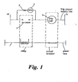
- this circuit can consist of a bulb or other visual or audible indicator connected across the trip contact as shown in figure 1 . The bulb is lit while the trip contact is open and the trip supply voltage is present.
- a corresponding circuit breaker trip circuit supervision is shown in GB-A-2 272 119 .
- An improved monitoring circuit uses an electrical relay in place of the bulb.
- the contacts of this relay are held open while the trip contact remains open and the trip supply voltage is present. Failure of the trip supply voltage causes the relay contacts to close, initiating an audible or visual alarm.
- the current flowing in the supervision circuit when the voltage is at its lowest value must be sufficient to light the bulb, or hold the relay contacts open.
- the current flowing in the supervision circuit when the voltage is at its highest must not be sufficient to trip the circuit breaker.
- the power dissipated by the supervision circuit can be excessive, at the highest voltage, particularly if the circuit is incorporated into the protective relay equipment which operates the trip contact.
- An aim of at least one aspect of the present invention is to ameliorate the problems associated with the high power dissipation across the resistive element.
- the invention provides a supervision circuit adapted for use in combination with a supervised circuit comprising at least one electrical component connected in series in a supply line from a supply voltage, the supervision circuit being connected across the electrical component and including a current sensing device, in which during normal operation of the supervised circuit the supervision circuit is adapted to draw a substantially constant current from the supply line independent of supply voltage fluctuations, and in which the current sensing device produces an output signal dependent upon the current drawn by the supervision circuit.
- the electrical component may, for example, comprise a switch which is adapted to connect or disconnect a load in the circuit to the supply voltage.
- the invention provides a trip circuit supervision circuit for use in combination with a trip circuit comprising a circuit breaker trip coil connected in series in a supply line from a supply voltage and a trip relay contact connected in series with the circuit breaker trip coil in the supply line, the trip circuit supervision circuit being connected across the relay trip contact and including a current sensing device, in which during normal operation the supervision circuit is adapted to draw a substantially constant current from the supply line independent of supply voltage fluctuations when the relay trip contact is open, and in which the current sensing device produces an output signal dependent upon the current drawn by the supervision circuit.
- the supervision circuit comprises a constant current source connected in series with the current sensing device.
- the prior art resistive load and bulb have been eliminated and replaced by a constant current circuit and a current sensing device.
- a bulb or other light emitting device could still be provided in addition as a simple check device, perhaps in series with the current sensing device.
- An advantage of the invention is that the current circuit draws a current which does not vary with small changes in supply voltage as is the case of a resistive load. This results in a more stable current which is easy to monitor by the current sensing device. It also consumes less power. The power dissipated in the trip protection circuit is no longer dependent on the square of the supply voltage as with resistive load.
- the output signal from the current sensing device may be used to drive a visual or audible warning device such as a bulb or siren. It could be logged by a computer or other device.
- the constant current source may comprise first and second constant current sources connected in series with each other.
- the use of the second constant current circuit acts as a safety back up in the event of failure of the first constant current source. If the first constant current circuit failed and produced a short circuit across the relay trip contact, sufficient current could flow to actuate the circuit breaker trip coil. The provision of the second constant current source prevents such a failure mode occurring by limiting the current.
- the current sensing device may comprise a light emitting diode connected in series with the constant current source which illuminates a photodiode.
- the photodiode may be connected to a DC supply and allows current to flow when illuminated by the diode to produce the output signal. This also provides a high degree of isolation to prevent the formation of undesirable ground loops.
- a switching means may be provided in series with the constant current source. By opening/closing the switching means it is possible to efficiently reduce the power consumed by the constant current source by switching the supervision circuit ON/OFF.
- the switch may be modulated by a suitable pulse train. As an example, using a square wave would halve the power dissipation.
- the invention provides a trip circuit including a trip circuit supervision circuit, in which the trip circuit comprises at least one circuit breaker trip coil adapted to open a circuit breaker in a supply line in response to a current flowing in the coil in excess of a threshold value and a relay trip contact connected in series with the trip coil and in which the trip circuit supervision circuit includes a current sensing device connected in series across the relay trip contact, the supervision circuit being adapted to draw a constant current from the supply line independent of supply voltage when the trip contact is open, the current sensing device producing an output signal indicative of the current drawn by the supervision circuit.
- the supervision circuit may comprise a constant current source and a current sensing device arranged in accordance with the first or second aspects of the invention.
- the trip circuit may further include a circuit breaker auxiliary contact connected in series with the trip coil and the protection relay trip contact.
- a trip circuit supervision circuit in accordance with the first or second aspects of the invention (for example an electrical circuit including a current sensing device adapted to draw substantially constant current independent of fluctuation in the supply voltage) may be provided in parallel with the auxiliary contact.
- a further circuit breaker auxiliary contact may be provided across the first auxiliary contact. This further contact may be in series with the constant current circuit of the trip circuit protection circuit.
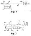
- FIG. 2 shows schematically a trip protection circuit in accordance with the invention which incorporates a trip circuit supervision circuit.
- the trip circuit comprises a normally-open protection relay trip contact 101 connected in series with a trip coil 102 of a circuit breaker in a line 103 between a positive and negative DC supply 104, 105.
- the trip coil opens the circuit breaker contacts (which are normally closed).
- the protection relay closes the trip contact 101 to connect the trip coil 102 to the positive supply.
- Current flowing in the line 103 through the trip coil 102 operates the circuit breaker to open its contacts.
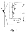
- trip circuit supervision circuit comprises a single constant current circuit 106 and a current sensor 107 connected in series with each other across the relay trip contact.
- the constant current circuit 106 comprises a high voltage MOSFET device 108, a transistor 109, a resistor 113 and a resistor 110.
- the voltage across the opposite ends of the protective element increases (i.e. trip contact)
- the current through resistor 113 increases and the rise in voltage across it starts to turn transistor 109 on and transistor 108 off to keep the current through the resistor constant. This enables a constant low level of current to be maintained through the trip circuit independent of supply voltage.
- the current sensing device 107 comprises a light emitting diode 111 which is illuminated due to current flowing through the circuit 106. This light falls upon a photodiode or phototransistor 112 as shown. This provides good electrical isolations between the trip circuit and the output of the current sensing device.
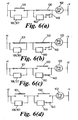
- FIG. 5 A refinement to the trip protection supervision circuit of figure 4 is shown in figure 5 .
- an additional constant current circuit 120 is provided in series with the first constant current circuit.
- FIG. 6 A refinement to the trip circuit is shown in figure 6 .
- an auxiliary circuit breaker contact 130 is provided in the DC line between the trip contact 101 and the trip coil 102.
- This auxiliary contact 130 is mechanically driven from the circuit breaker and is normally closed, but opens as the circuit breaker opens to break the circuit.
- a supervision circuit is provided by a constant current source/current sensing device 150 (as shown in figure 4 or figure 5 ) provided across the ends of auxiliary contact 130 (as shown in figure 6 ).
- a second auxiliary contact 140 is provided in series with the current sensing device across the contact 130. This second contact 140 works in opposition to contact 130 so that when contact 130 is open contact 140 is closed. This allows trip circuit supervision to be performed even when the breaker is in its open state.
- the protection relay trip contact closes, 130 is closed. In this condition no current flows through the first trip circuit supervision circuit as its terminals are short-circuited. This is a genuine condition to trip the circuit breaker, it exists for a short time only, and by using delays in monitoring the output of the two current sensing devices, no alarm is initiated.
- the protection relay contact opens and current flows through the Trip Coil and both current sensing devices. This current is well below that required to trip the circuit breaker. If the current drops to a low level (indicating an open circuit in the trip circuit) then the output from both current sensing devices can be used to initiate an alarm.
- a switching device 200 is provided in series with the two constant current sources 106, 120 and the current sensor 107 of the embodiment of Figure 3 .
- the switch By modulating the switch with a train of ON/OFF pulses 201, the current drain can be reduced. This could enable more circuits to be monitored within a given space as less heat would be dissipated.
- the switch could also be incorporated with a circuit such as shown in Figure 2 in which only a single constant current source is provided. Although a square wave is shown, other pulse trains (perhaps with unequal duty cycles) could be employed.
- a "drop-off delay circuit” comprising an R-C circuit with one capacitor C1 in parallel with a resistor R1. This provides a controllable time delay (by suitable selection of the values of C1 and R1), so that the circuit can provide its own time delays. This enables it to function for short periods when no current flows.
Landscapes
- Keying Circuit Devices (AREA)
- Arrangements For Transmission Of Measured Signals (AREA)
- Extrusion Moulding Of Plastics Or The Like (AREA)
- Emergency Protection Circuit Devices (AREA)
Claims (8)
- Auslöseschaltung, umfassend wenigstens eine Schaltungsunterbrecher-Auslösespule (102), die die Kontakte eines Schaltungsunterbrechers in einer Stromleitung aufgrund eines Stroms öffnen kann, der in der Auslösespule (102) fließt und einen Schwellenwert übersteigt, ferner umfassend einen Relais-Auslösekontakt (101), der im Falle eines Fehlers in der Stromleitung geschlossen werden kann und über eine Zufuhrleitung (103) an eine Lieferspannung (104, 105) in Reihe mit der Auslösespule (102) angeschlossen ist, und umfassend eine Überwachungsschaltung, die mit dem Relais-Auslösekontakt (101) verbunden ist und eine Stromfühler-Vorrichtung (107) aufweist, wobei die Überwachungsschaltung in der Lage ist, aus der Lieferspannung (104, 105) einen Strom herzuleiten und ein Ausgangssignal zu erzeugen, das den hergeleiteten Strom anzeigt, dadurch gekennzeichnet, daß die Überwachungsschaltung des weiteren eine konstante Stromschaltung (106) aufweist, die mit der Stromabtast-Vorrichtung (107) in Reihe geschaltet ist, um von der Lieferspannung einen konstanten Strom aufzunehmen, und zwar unabhängig von Spannungsschwankungen der Lieferspannung, sobald der Relais-Auslösekontakt (101) geöffnet ist und die Lieferspannung in der Zufuhrleitung auftritt.
- Auslöseschaltung nach Anspruch 1, dadurch gekennzeichnet, daß die konstante Stromschaltung (106) eine konstante Stromquelle (106) ist.
- Auslöseschaltung nach Anspruch 2, dadurch gekennzeichnet, daß die konstante Stromquelle erste (106) und zweite (120) Quellen aufweist, die miteinander in Reihe geschaltet sind.
- Auslöseschaltung nach einem der vorhergehenden Ansprüche, dadurch gekennzeichnet, daß sie einen Schaltungsunterbrecher-Hilfskontakt (130) aufweist, der mit der Auslösespule (102) und dem Relais-Auslösekontakt (101) in Reihe geschaltet ist.
- Auslöseschaltung nach Anspruch 4, gekennzeichnet durch einen zweiten Auslöseschaltungs-Überwachungsschaltkreis (150), der eine Stromfühler-Vorrichtung aufweist, die mit dem Schaltungsunterbrecher-Hilfskontakt (130) parallel liegt.
- Auslöseschaltung nach Anspruch 5, dadurch gekennzeichnet, daß ein weiterer Schaltungsunterbrecher-Hilfskontakt (140) parallel zu dem Schaltungsunterbrecher-Hilfskontakt (130) vorgesehen ist.
- Auslöseschaltung nach einem der vorhergehenden Ansprüche, gekennzeichnet durch eine sichtbare oder hörbare Warneinrichtung, die durch ein Ausgangssignal der Stromfühler-Vorrichtung (107) betrieben wird.
- Auslöseschaltung nach einem der vorhergehenden Ansprüche 1 bis 6, dadurch gekennzeichnet, daß die Stromfühler-Vorrichtung (107) eine Licht emittierende Diode (111) aufweist.
Applications Claiming Priority (2)
| Application Number | Priority Date | Filing Date | Title |
|---|---|---|---|
| GBGB9822515.4A GB9822515D0 (en) | 1998-10-16 | 1998-10-16 | Improvements relating to monitoring apparatus for electrical circuits |
| GB9822515 | 1998-10-16 |
Publications (3)
| Publication Number | Publication Date |
|---|---|
| EP0994546A2 EP0994546A2 (de) | 2000-04-19 |
| EP0994546A3 EP0994546A3 (de) | 2001-12-05 |
| EP0994546B1 true EP0994546B1 (de) | 2010-02-17 |
Family
ID=10840636
Family Applications (1)
| Application Number | Title | Priority Date | Filing Date |
|---|---|---|---|
| EP99308159A Expired - Lifetime EP0994546B1 (de) | 1998-10-16 | 1999-10-15 | Verbesserungen bezüglich Vorrichtungen zur Überwachung für elektrische Schaltungen |
Country Status (7)
| Country | Link |
|---|---|
| US (1) | US6359763B1 (de) |
| EP (1) | EP0994546B1 (de) |
| CN (1) | CN1135396C (de) |
| AT (1) | ATE458293T1 (de) |
| CA (1) | CA2286514C (de) |
| DE (1) | DE69942016D1 (de) |
| GB (2) | GB9822515D0 (de) |
Families Citing this family (18)
| Publication number | Priority date | Publication date | Assignee | Title |
|---|---|---|---|---|
| DE19954460C2 (de) * | 1999-11-12 | 2002-02-28 | Pilz Gmbh & Co | Sicherheitsschaltgerät zum Ein- und sicheren Ausschalten eines elektrischen Verbrauchers, insbesondere einer elektrisch angetriebenen Maschine |
| US6744254B2 (en) * | 2002-03-08 | 2004-06-01 | Eaton Corporation | Breaker failure annunciator system |
| US6967445B1 (en) * | 2004-04-19 | 2005-11-22 | Jewell Dan J | Circuit continuity and function monitor |
| EP2182537A1 (de) * | 2008-10-31 | 2010-05-05 | Siemens AG | Relaisschaltung |
| CN105206449B (zh) * | 2009-11-16 | 2018-01-02 | Abb 技术有限公司 | 使输电线路或配电线路的电流断路的装置和方法以及限流布置 |
| FR2960093B1 (fr) * | 2010-05-11 | 2013-07-05 | Areva T & D Prot & Controle Sa | Dispositif de protection a associer a un dispositif de coupure de courant dans un circuit electrique a duree de vie accrue |
| EP2407993B1 (de) | 2010-07-15 | 2013-09-04 | ABB Technology AG | Verbessertes Überwachungsrelais für Auslöseschaltung für Nieder- und Mittelspannungsanwendungen |
| JP6058315B2 (ja) * | 2012-08-17 | 2017-01-11 | 株式会社東芝 | デジタル保護リレー |
| JP6308486B2 (ja) | 2012-09-13 | 2018-04-11 | パナソニックIpマネジメント株式会社 | リレー溶着検出装置 |
| CN103529349A (zh) * | 2013-10-21 | 2014-01-22 | 天津市品通电力科技有限公司 | 开关柜保护回路断线监测装置 |
| KR101589480B1 (ko) * | 2014-06-13 | 2016-01-28 | 엘에스산전 주식회사 | 차단기 및 차단기 제어 방법 |
| AU2019212433B2 (en) * | 2018-01-23 | 2021-08-12 | Hitachi Energy Ltd | A method for supervising a trip circuit and a trip supervision relay therof |
| CN109216100B (zh) * | 2018-09-09 | 2024-01-02 | 湛江电力有限公司 | 一种电力开关真空断路器的监控指示电路 |
| CN111969550A (zh) * | 2019-05-20 | 2020-11-20 | 陈锡瑜 | 高压断路器跳脱方法及其回路系统设备 |
| CN110504657B (zh) * | 2019-07-31 | 2023-12-08 | 宁波天安(集团)股份有限公司 | 中压环网柜失电跳闸装置 |
| CN113092997B (zh) * | 2021-03-29 | 2024-08-27 | 南方电网数字电网研究院有限公司 | 断路器监测电路及低压保护装置 |
| CN113872167B (zh) * | 2021-11-24 | 2024-05-28 | 国网重庆市电力公司电力科学研究院 | 防止直流系统接地故障引起保护误动或拒动的装置及方法 |
| US20240380308A1 (en) * | 2023-05-09 | 2024-11-14 | Ademco Inc. | Constant current circuit driver |
Family Cites Families (8)
| Publication number | Priority date | Publication date | Assignee | Title |
|---|---|---|---|---|
| GB2034136B (en) | 1978-09-30 | 1982-09-08 | Plessey Co Ltd | Fuse alarm system |
| US4520417A (en) * | 1983-02-14 | 1985-05-28 | Raychem Corporation | Electrical monitoring systems |
| DE3407311A1 (de) * | 1984-02-24 | 1985-08-29 | Siemens AG, 1000 Berlin und 8000 München | Schaltungsanordnung zur ueberwachung einer spannung |
| US4992723A (en) * | 1989-03-31 | 1991-02-12 | Square D Company | Fault-powered power supply |
| GB2272119B (en) * | 1992-10-30 | 1996-04-10 | Gec Alsthom Ltd | Circuit breaker trip circuit supervision |
| US5461358A (en) * | 1993-09-08 | 1995-10-24 | Delco Electronics Corporation | Resistance measurement circuit for external deployment path of sir system |
| JP3325187B2 (ja) * | 1996-07-29 | 2002-09-17 | アンリツ株式会社 | 複極性電流検出装置 |
| US5754113A (en) * | 1996-10-28 | 1998-05-19 | Eaton Corporation | Circuit monitor for plural electrical switching apparatus |
-
1998
- 1998-10-16 GB GBGB9822515.4A patent/GB9822515D0/en not_active Ceased
-
1999
- 1999-10-15 CA CA2286514A patent/CA2286514C/en not_active Expired - Fee Related
- 1999-10-15 US US09/419,431 patent/US6359763B1/en not_active Expired - Fee Related
- 1999-10-15 DE DE69942016T patent/DE69942016D1/de not_active Expired - Lifetime
- 1999-10-15 AT AT99308159T patent/ATE458293T1/de not_active IP Right Cessation
- 1999-10-15 EP EP99308159A patent/EP0994546B1/de not_active Expired - Lifetime
- 1999-10-15 GB GB9924336A patent/GB2342795B/en not_active Expired - Fee Related
- 1999-10-16 CN CNB991250311A patent/CN1135396C/zh not_active Expired - Fee Related
Also Published As
| Publication number | Publication date |
|---|---|
| US6359763B1 (en) | 2002-03-19 |
| CA2286514A1 (en) | 2000-04-16 |
| GB9822515D0 (en) | 1998-12-09 |
| CN1262444A (zh) | 2000-08-09 |
| EP0994546A2 (de) | 2000-04-19 |
| GB2342795A (en) | 2000-04-19 |
| CA2286514C (en) | 2011-07-26 |
| GB9924336D0 (en) | 1999-12-15 |
| CN1135396C (zh) | 2004-01-21 |
| DE69942016D1 (de) | 2010-04-01 |
| EP0994546A3 (de) | 2001-12-05 |
| GB2342795B (en) | 2002-09-18 |
| ATE458293T1 (de) | 2010-03-15 |
Similar Documents
| Publication | Publication Date | Title |
|---|---|---|
| EP0994546B1 (de) | Verbesserungen bezüglich Vorrichtungen zur Überwachung für elektrische Schaltungen | |
| US4983955A (en) | Electric power supply circuit monitoring systems | |
| US4554607A (en) | Fuse loss indicating circuit | |
| US4421976A (en) | System for monitoring heater elements of electric furnaces | |
| US5387899A (en) | Alarm system with monitoring circuit for detecting a cut or short in a pair of wires | |
| US3974492A (en) | Alarm system | |
| CN114362092B (zh) | 一种负载短路保护电路及电子设备 | |
| US6492799B1 (en) | Monitor circuit for a current limiting device | |
| KR101074287B1 (ko) | 전력용 차단기의 진단 기능을 내장한 보호 계전기 | |
| EP0126704B1 (de) | Anzeigevorrichtung | |
| CN110648487A (zh) | 烟雾监测电路及显示屏 | |
| US6813129B2 (en) | Self-diagnostic solid state relay for detection of open load circuit | |
| US4849734A (en) | Self-diagnostic circuit for alarm-systems | |
| JP2018054398A (ja) | 地絡電流検出器 | |
| EP0991042A2 (de) | Signalgeber und Überwachungssystem | |
| US4788446A (en) | Monitoring circuit for an electric or electronic module | |
| KR102036647B1 (ko) | 전원 단락보호 회로 | |
| EP3446391B1 (de) | Relaisschutzsystem | |
| EP0502437A2 (de) | Apparat zur Bestimmung der Ladung einer Batterie, insbesondere in einem Fahrzeug | |
| KR100369716B1 (ko) | 자동 복귀형 고속 차단기 | |
| SU669373A1 (ru) | Устройство дл пожарной сигнализации | |
| ITMI951221A1 (it) | Centralino per l'alimentazione di energia elettrica particolarmente per uso domestico | |
| KR20050077911A (ko) | 간판등 제어의 안전성을 높이는 방법 | |
| KR100387673B1 (ko) | 자동차의릴레이단선알림장치 | |
| EP2237644A1 (de) | Überwachungseinheit für eine Hochleistungs-LED und Signalisierungsvorrichtung |
Legal Events
| Date | Code | Title | Description |
|---|---|---|---|
| PUAI | Public reference made under article 153(3) epc to a published international application that has entered the european phase |
Free format text: ORIGINAL CODE: 0009012 |
|
| AK | Designated contracting states |
Kind code of ref document: A2 Designated state(s): AT BE CH CY DE DK ES FI FR GB GR IE IT LI LU MC NL PT SE |
|
| AX | Request for extension of the european patent |
Free format text: AL;LT;LV;MK;RO;SI |
|
| PUAL | Search report despatched |
Free format text: ORIGINAL CODE: 0009013 |
|
| AK | Designated contracting states |
Kind code of ref document: A3 Designated state(s): AT BE CH CY DE DK ES FI FR GB GR IE IT LI LU MC NL PT SE |
|
| AX | Request for extension of the european patent |
Free format text: AL;LT;LV;MK;RO;SI |
|
| 17P | Request for examination filed |
Effective date: 20020326 |
|
| AKX | Designation fees paid |
Free format text: AT BE CH CY DE DK ES FI FR GB GR IE IT LI LU MC NL PT SE |
|
| RAP1 | Party data changed (applicant data changed or rights of an application transferred) |
Owner name: ALSTOM UK |
|
| RAP1 | Party data changed (applicant data changed or rights of an application transferred) |
Owner name: AREVA T&D UK LTD. |
|
| 17Q | First examination report despatched |
Effective date: 20080717 |
|
| GRAP | Despatch of communication of intention to grant a patent |
Free format text: ORIGINAL CODE: EPIDOSNIGR1 |
|
| GRAS | Grant fee paid |
Free format text: ORIGINAL CODE: EPIDOSNIGR3 |
|
| GRAA | (expected) grant |
Free format text: ORIGINAL CODE: 0009210 |
|
| AK | Designated contracting states |
Kind code of ref document: B1 Designated state(s): AT BE CH CY DE DK ES FI FR GB GR IE IT LI LU MC NL PT SE |
|
| REG | Reference to a national code |
Ref country code: GB Ref legal event code: FG4D |
|
| REG | Reference to a national code |
Ref country code: CH Ref legal event code: EP |
|
| REG | Reference to a national code |
Ref country code: IE Ref legal event code: FG4D |
|
| REF | Corresponds to: |
Ref document number: 69942016 Country of ref document: DE Date of ref document: 20100401 Kind code of ref document: P |
|
| REG | Reference to a national code |
Ref country code: SE Ref legal event code: TRGR |
|
| REG | Reference to a national code |
Ref country code: NL Ref legal event code: VDEP Effective date: 20100217 |
|
| PG25 | Lapsed in a contracting state [announced via postgrant information from national office to epo] |
Ref country code: PT Free format text: LAPSE BECAUSE OF FAILURE TO SUBMIT A TRANSLATION OF THE DESCRIPTION OR TO PAY THE FEE WITHIN THE PRESCRIBED TIME-LIMIT Effective date: 20100617 Ref country code: ES Free format text: LAPSE BECAUSE OF FAILURE TO SUBMIT A TRANSLATION OF THE DESCRIPTION OR TO PAY THE FEE WITHIN THE PRESCRIBED TIME-LIMIT Effective date: 20100528 |
|
| PG25 | Lapsed in a contracting state [announced via postgrant information from national office to epo] |
Ref country code: FI Free format text: LAPSE BECAUSE OF FAILURE TO SUBMIT A TRANSLATION OF THE DESCRIPTION OR TO PAY THE FEE WITHIN THE PRESCRIBED TIME-LIMIT Effective date: 20100217 Ref country code: AT Free format text: LAPSE BECAUSE OF FAILURE TO SUBMIT A TRANSLATION OF THE DESCRIPTION OR TO PAY THE FEE WITHIN THE PRESCRIBED TIME-LIMIT Effective date: 20100217 |
|
| PG25 | Lapsed in a contracting state [announced via postgrant information from national office to epo] |
Ref country code: NL Free format text: LAPSE BECAUSE OF FAILURE TO SUBMIT A TRANSLATION OF THE DESCRIPTION OR TO PAY THE FEE WITHIN THE PRESCRIBED TIME-LIMIT Effective date: 20100217 Ref country code: GR Free format text: LAPSE BECAUSE OF FAILURE TO SUBMIT A TRANSLATION OF THE DESCRIPTION OR TO PAY THE FEE WITHIN THE PRESCRIBED TIME-LIMIT Effective date: 20100518 Ref country code: CY Free format text: LAPSE BECAUSE OF FAILURE TO SUBMIT A TRANSLATION OF THE DESCRIPTION OR TO PAY THE FEE WITHIN THE PRESCRIBED TIME-LIMIT Effective date: 20100217 Ref country code: BE Free format text: LAPSE BECAUSE OF FAILURE TO SUBMIT A TRANSLATION OF THE DESCRIPTION OR TO PAY THE FEE WITHIN THE PRESCRIBED TIME-LIMIT Effective date: 20100217 |
|
| PGFP | Annual fee paid to national office [announced via postgrant information from national office to epo] |
Ref country code: IE Payment date: 20100902 Year of fee payment: 12 |
|
| PLBE | No opposition filed within time limit |
Free format text: ORIGINAL CODE: 0009261 |
|
| STAA | Information on the status of an ep patent application or granted ep patent |
Free format text: STATUS: NO OPPOSITION FILED WITHIN TIME LIMIT |
|
| 26N | No opposition filed |
Effective date: 20101118 |
|
| PG25 | Lapsed in a contracting state [announced via postgrant information from national office to epo] |
Ref country code: DK Free format text: LAPSE BECAUSE OF FAILURE TO SUBMIT A TRANSLATION OF THE DESCRIPTION OR TO PAY THE FEE WITHIN THE PRESCRIBED TIME-LIMIT Effective date: 20100217 |
|
| PGFP | Annual fee paid to national office [announced via postgrant information from national office to epo] |
Ref country code: DE Payment date: 20101022 Year of fee payment: 12 |
|
| PG25 | Lapsed in a contracting state [announced via postgrant information from national office to epo] |
Ref country code: IT Free format text: LAPSE BECAUSE OF FAILURE TO SUBMIT A TRANSLATION OF THE DESCRIPTION OR TO PAY THE FEE WITHIN THE PRESCRIBED TIME-LIMIT Effective date: 20100217 |
|
| PG25 | Lapsed in a contracting state [announced via postgrant information from national office to epo] |
Ref country code: MC Free format text: LAPSE BECAUSE OF NON-PAYMENT OF DUE FEES Effective date: 20101031 |
|
| REG | Reference to a national code |
Ref country code: CH Ref legal event code: PL |
|
| GBPC | Gb: european patent ceased through non-payment of renewal fee |
Effective date: 20101015 |
|
| PG25 | Lapsed in a contracting state [announced via postgrant information from national office to epo] |
Ref country code: LI Free format text: LAPSE BECAUSE OF NON-PAYMENT OF DUE FEES Effective date: 20101031 Ref country code: CH Free format text: LAPSE BECAUSE OF NON-PAYMENT OF DUE FEES Effective date: 20101031 |
|
| PG25 | Lapsed in a contracting state [announced via postgrant information from national office to epo] |
Ref country code: GB Free format text: LAPSE BECAUSE OF NON-PAYMENT OF DUE FEES Effective date: 20101015 |
|
| PGFP | Annual fee paid to national office [announced via postgrant information from national office to epo] |
Ref country code: SE Payment date: 20111021 Year of fee payment: 13 Ref country code: FR Payment date: 20111103 Year of fee payment: 13 |
|
| REG | Reference to a national code |
Ref country code: IE Ref legal event code: MM4A |
|
| PG25 | Lapsed in a contracting state [announced via postgrant information from national office to epo] |
Ref country code: LU Free format text: LAPSE BECAUSE OF NON-PAYMENT OF DUE FEES Effective date: 20101015 |
|
| PG25 | Lapsed in a contracting state [announced via postgrant information from national office to epo] |
Ref country code: IE Free format text: LAPSE BECAUSE OF NON-PAYMENT OF DUE FEES Effective date: 20111015 |
|
| REG | Reference to a national code |
Ref country code: FR Ref legal event code: ST Effective date: 20130628 |
|
| PG25 | Lapsed in a contracting state [announced via postgrant information from national office to epo] |
Ref country code: DE Free format text: LAPSE BECAUSE OF NON-PAYMENT OF DUE FEES Effective date: 20130501 Ref country code: SE Free format text: LAPSE BECAUSE OF NON-PAYMENT OF DUE FEES Effective date: 20121016 |
|
| REG | Reference to a national code |
Ref country code: DE Ref legal event code: R119 Ref document number: 69942016 Country of ref document: DE Effective date: 20130501 |
|
| PG25 | Lapsed in a contracting state [announced via postgrant information from national office to epo] |
Ref country code: FR Free format text: LAPSE BECAUSE OF NON-PAYMENT OF DUE FEES Effective date: 20121031 |