EP0994519A2 - Electrolyte solution filling method and battery structure of lithium secondary battery - Google Patents
Electrolyte solution filling method and battery structure of lithium secondary battery Download PDFInfo
- Publication number
- EP0994519A2 EP0994519A2 EP99120325A EP99120325A EP0994519A2 EP 0994519 A2 EP0994519 A2 EP 0994519A2 EP 99120325 A EP99120325 A EP 99120325A EP 99120325 A EP99120325 A EP 99120325A EP 0994519 A2 EP0994519 A2 EP 0994519A2
- Authority
- EP
- European Patent Office
- Prior art keywords
- battery
- electrolyte solution
- core
- lithium secondary
- secondary battery
- Prior art date
- Legal status (The legal status is an assumption and is not a legal conclusion. Google has not performed a legal analysis and makes no representation as to the accuracy of the status listed.)
- Withdrawn
Links
Images


Classifications
-
- H—ELECTRICITY
- H01—ELECTRIC ELEMENTS
- H01M—PROCESSES OR MEANS, e.g. BATTERIES, FOR THE DIRECT CONVERSION OF CHEMICAL ENERGY INTO ELECTRICAL ENERGY
- H01M50/00—Constructional details or processes of manufacture of the non-active parts of electrochemical cells other than fuel cells, e.g. hybrid cells
- H01M50/60—Arrangements or processes for filling or topping-up with liquids; Arrangements or processes for draining liquids from casings
- H01M50/609—Arrangements or processes for filling with liquid, e.g. electrolytes
- H01M50/627—Filling ports
-
- H—ELECTRICITY
- H01—ELECTRIC ELEMENTS
- H01M—PROCESSES OR MEANS, e.g. BATTERIES, FOR THE DIRECT CONVERSION OF CHEMICAL ENERGY INTO ELECTRICAL ENERGY
- H01M10/00—Secondary cells; Manufacture thereof
- H01M10/05—Accumulators with non-aqueous electrolyte
- H01M10/052—Li-accumulators
-
- Y—GENERAL TAGGING OF NEW TECHNOLOGICAL DEVELOPMENTS; GENERAL TAGGING OF CROSS-SECTIONAL TECHNOLOGIES SPANNING OVER SEVERAL SECTIONS OF THE IPC; TECHNICAL SUBJECTS COVERED BY FORMER USPC CROSS-REFERENCE ART COLLECTIONS [XRACs] AND DIGESTS
- Y02—TECHNOLOGIES OR APPLICATIONS FOR MITIGATION OR ADAPTATION AGAINST CLIMATE CHANGE
- Y02E—REDUCTION OF GREENHOUSE GAS [GHG] EMISSIONS, RELATED TO ENERGY GENERATION, TRANSMISSION OR DISTRIBUTION
- Y02E60/00—Enabling technologies; Technologies with a potential or indirect contribution to GHG emissions mitigation
- Y02E60/10—Energy storage using batteries
-
- Y—GENERAL TAGGING OF NEW TECHNOLOGICAL DEVELOPMENTS; GENERAL TAGGING OF CROSS-SECTIONAL TECHNOLOGIES SPANNING OVER SEVERAL SECTIONS OF THE IPC; TECHNICAL SUBJECTS COVERED BY FORMER USPC CROSS-REFERENCE ART COLLECTIONS [XRACs] AND DIGESTS
- Y02—TECHNOLOGIES OR APPLICATIONS FOR MITIGATION OR ADAPTATION AGAINST CLIMATE CHANGE
- Y02P—CLIMATE CHANGE MITIGATION TECHNOLOGIES IN THE PRODUCTION OR PROCESSING OF GOODS
- Y02P70/00—Climate change mitigation technologies in the production process for final industrial or consumer products
- Y02P70/50—Manufacturing or production processes characterised by the final manufactured product
Definitions
- This invention relates to a method for filling an electrolyte solution into a lithium secondary battery; said method capable of filling electrolyte solution into a case and extracting an excessive electrolyte solution therefrom, and sealing easily a battery, thereby the simplification of fabrication process, the reduction in the production cost, and the improvement in compaction of energy density can be achieved, and a battery structure of the lithium secondary battery; said battery having a reduced current collection resistance from positive electrodes and negative electrodes, and a narrowed deviation in the fluctuation in the resistances among the tabs engaged in current collection as well, and having a simple structure as a battery so as to enable to make an easier assembly of the battery and to effectuate the aforementioned method for filling an electrolyte solution into the case easily.
- the lithium secondary battery has been widely used as a power battery for handy electronic appliances such as personal handy phone systems, video tape recorders, notebook-type computers, or the like. Additionally, in the case of a lithium secondary battery, a single battery can generate a voltage of approximately 4 V, and this level of voltage is higher than that of conventional secondary batteries such as a lead battery, or the like, and its energy density is also high. Thus, much attention has been paid to it not only as a power source for the aforementioned handy electronic appliances, but also as a motor driving power source for an electric vehicle (EV) or a hybrid electric vehicle (HEV), of which penetration among the general public is being earnestly planned as a low-pollution vehicle due to the recent development in the environmental problems.
- EV electric vehicle
- HEV hybrid electric vehicle
- a lithium- transition metal compound oxide as a positive active material a carbon material as a negative active material, and an organic electrolyte solution obtained by dissolving a Li-ion forming electrolyte in an organic solvent as an electrolyte solution are used.
- an organic electrolyte solution obtained by dissolving a Li-ion forming electrolyte in an organic solvent as an electrolyte solution are used.
- an internal electrode body as a portion where battery reaction is carried out are available various types.
- a sandwiched-type internal electrode body in which a separator is sandwiched between a positive electrode and a negative electrode is used.
- the positive electrode and the negative electrode those that are formed in a disk like shape, or in a coin like shape by subjecting positive material and negative material to press-forming processing or the like, respectively are suitably used.
- a wound-type internal electrode body 1 being formed by winding around the outer periphery of a hollow cylinder-shaped core 6 a positive electrode 2 having a tab 5 for current collection and a negative electrode 3 having tab 5 for current collection, in a such manner that the positive electrode 2 and negative electrode 3 are not brought into direct contact with each other, by sandwiching a separator 4 between the positive electrode 2 and the negative electrode 3.
- the length of the core 6 is set equal to the width of the positive electrode 2 and that of the negative electrode 3.
- an electrolyte solution a non-aqueous electrolyte solution (hereinafter to be referred to as an "electrolyte solution”), which is obtained by dissolving a lithium electrolyte in an organic solvent, is used.
- electrolyte solution a non-aqueous electrolyte solution (hereinafter to be referred to as an "electrolyte solution”), which is obtained by dissolving a lithium electrolyte in an organic solvent, is used.
- electrolyte solution a non-aqueous electrolyte solution
- electrolyte solution a non-aqueous electrolyte solution
- a battery having a relatively large capacity (hereinafter to be referred to as a "large capacity battery”) to be applied to an EV, or the like, the size of a battery itself will necessarily become large.
- the use of the wound-type internal electrode body 1 shown in Fig. 18 requires a larger space for housing the current collection tabs 5 at both ends or one end of the case for the battery.
- a hollow cylinder-shaped type core is generally used for the core 6, the absolute volume to be occupied by these spaces inside the case for battery becomes large.
- an electrolyte solution is filled into a case for a large capacity battery by using a technique similar to that for the above-described small capacity battery, an expensive electrolyte solution is used not in an economic manner. This would bring the increase in the production cost and the reduction in the energy density of the battery, as well. Furthermore, it is not preferable, from the viewpoints of durability, to keep it such a state that metal members other than the internal electrode body, sealing members of the battery case, and the like, are always in contact with the electrolyte solution since it causes often the leakage of the electrolyte solution, the corrosion of said members, or the like.
- the electrolyte solution is required to fill in an amount sufficient to impregnate the internal electrode body properly even in the case of a large internal electrode body having a large battery area. And in the case where this is not fulfilled, not only the desired battery performance cannot be attained, but also the fluctuation in the performance of respective batteries will take place. Accordingly, in the case of a large capacity battery, it is preferable to impregnate the internal electrode body thoroughly in an excessive amount of an electrolyte solution under a reduced atmosphere, and thereafter the excessive electrolyte solution is removed.
- the present inventors have extensively studied, in particular, the simplification of a method for filling an electrolyte solution in the production of a large capacity battery. As a result, they reached the present invention to be described later. Moreover, various studies have been made at the same time so as to find out not only a battery structure suitable for using the method filling an electrolyte solution according to the present invention, but also a battery structure capable of improving the battery performance and productivity even in the case where the method for filling an electrolyte solution according to the present invention is not used.
- a tab is connected directly with an external terminal of the battery, that is, directly with an electrode terminal to extract current out from the battery, or is connected with an internal terminal thereof, that is, a terminal to which the tabs are intermediately connected collectively inside the battery. Accordingly, in the case where the tabs are connected with the internal terminal, it is necessary that the internal terminal is made conductive to the external terminal to form a current path between the tabs and the external terminal.
- a lithium secondary battery 27 in which a series of flexible leads (equivalent to "tabs" in meaning) 37 is sandwiched between the electrode terminal 38 and the hold-down hardware 33, with forming a warping shape as shown in Fig. 16; said leads 37 being welded to the electrode terminal 38 by laser beam.
- the electrode terminal 38 is attached to a cap (ceiling plate) 29 by using a nut 34, and the cap 29 is provided with not only electrolyte solution injection opening 32 which is to be sealed with a blank cap 30 but also a pressure release valve 26.
- the leads 37 may be sandwiched with the hold-down hardware 33 at any position of the outer periphery of the electrode terminal 38,as a corollary, the leads 37 disposed in the inner periphery of the internal electrode body 35 becomes long, and, on the contrary, the leads 37 disposed in the outer periphery becomes short.
- the quantity of current flow in each lead 37 is different due to the difference in resistance of each lead 37, depending upon its length, there is a fear that the uniformity in the battery reaction cannot be maintained when used as a battery for an EV which requires the frequent flow of a large current.
- the leads 37 may be attached to any position of the outer periphery of the electrode terminals 38 with laser welding, and the structure at the end portion of the battery is complicated and various parts are installed therein, as shown in Fig. 16, thus the work efficiency (productivity) of the battery assembly is considered to be not necessarily good.
- a battery 27 disclosed in JP-A-9-92338 has the configuration at its both ends, as shown in Fig. 16. It is stated in the laid-open invention that the injection of electrolyte solution is carried out by injecting electrolyte solution from one end of the injection opening 32 for electrolyte solution, while keeping the interior of the battery 27 is under a reduced pressure by deaerating from the other end of the injection opening 32 for electrolyte solution, and this step should be repeated several times. However, it is not advantageous to assemble a battery with the repetition of such steps several times. Moreover, it is not advantageous to provide the both ends with the injection openings 32 for electrolyte solution which eventually will be sealed since the leakage of the electrolyte solution and the decrease in air tightness are liable to occur.
- the battery disclosed in JP-A-9-92338 has been proposed to prevent damage to leads 37 under severe vibrations when the battery is used as for the battery for an EV. Therefore, it proposes to use a flexible material for lead 37. At the same time, it refers to the reduction in internal resistance by virtue of a broadened welded portion between the leads 37 and the electrode terminals 38 formed by laser welding, however, it is quite silent about the reduction in fluctuation in the resistance among respective leads 37.
- Another problem is how to secure the durability against vibration during driving since the durability is an essential requirement in the case of a battery for an EV.
- the internal electrode body vibrates or moves inside the battery case, there is a fear that the electrode active materials coated on the positive electrode and the negative electrode are peeled, thereby the battery capacity is reduced.
- the end surface of the internal electrode body is apt to be deformed from an initial plain shape into a shape such as spiral waves or the like due to vibration, and such a deformation of the internal electrode becomes a cause of an unfavorable uneven battery reaction.
- JP-A-9-92241 a battery 28 having such a structure that, as shown in Fig. 15, an electrode pole 25 having its lower surface covered with insulator collar 39 is inserted into a hollow portion of a cylindrical core 31 from which an electrode spiral body 36 (equivalent to the internal electrode body 1) is formed, and said electrode pole 25 is fixed to a cap 29 with a nut 34.
- JP-A-1-175176 a battery structure that an internal electrode body formed by inserting a bar-shaped insulating body into a portion formed by using a tentative core which was removed thereafter is housed in the battery case.
- the inner periphery surface of the battery case 19 and the electrode pole 25 function only as a stopper so as to suppress the movement of the electrode spiral body 36 in the diameter direction.
- it does not suppress the movement in the diameter direction, and it has such a structure that the movement in the longitudinal direction of the electrode spiral body 36 take places easily in the distance of the gap with the electrode pole 25. If the movement to the longitudinal direction of the electrode spiral body 36 takes place, the electrode spiral body 36 collides with the electrode pole 25, which would damage the leads 37 (equivalent to tabs 5) attached on the end surfaces of the electrode spiral body 36.
- the present invention has been made so as to solve problems of the prior art mentioned above.
- the present invention is aiming to keep at the minimum level as required the amount of the excessive electrolyte solution to be filled inside the battery on the occasion of forming a comparatively large capacity battery.
- the present invention is aiming to provide a simply operative method for filling an electrolyte solution, and provide a battery structure capable of operating said filling method easily.
- the present invention is aiming at to attain the improvement in the battery performance such as reduction in current collection resistance and improvement of anti-vibration performance.
- one of the aspects of the present invention is directed to a method for filling an electrolyte solution into a lithium secondary battery comprising an internal electrode body formed by winding a positive electrode, and a negative electrode, with sandwiching a separator therebetween around the outer periphery of a core, and an electrolyte solution to impregnate said internal electrode, which comprises the steps of :
- the method for filling an electrolyte solution of the present invention is preferably used in a battery where the electrolyte solution injection opening is disposed in the center of one end surface of the battery and/or the core is disposed in the center of the battery.
- one nozzle may be used as a nozzle for injection of electrolyte solution and a nozzle for extraction of electrolyte solution as well. It is preferable to insert the tip of the nozzle for injection of electrolyte solution or that of the nozzle for extraction of electrolyte solution in such a manner that it reaches the other end of the battery to implement inject or extraction of electrolyte solution under this state.
- the electrolyte solution injection opening is enclosed from outside with screwing or pressure fitting or filling with a sealing material to implement sealing of the battery easily.
- the assembly work of the battery becomes preferably good, if the electrolyte solution is extracted and/or injected by using a pipe as a body member of the battery case after the battery is sealed by subjecting the both ends of the pipe to caulking processing in order to occlude the ends of the pipe with the cap.
- the method for filling an electrolyte solution the present invention is suitably applied to a battery having the battery capacity of 2 Ah or more.
- a battery structure of a lithium secondary battery comprising an internal electrode body formed by winding a positive electrode, and a negative electrode, with sandwiching a separator therebetween around the outer periphery of a core, and an electrolyte solution to impregnate said internal electrode body; wherein an electrolyte solution injection opening is provided in an extended position of the through hole of the core on one end surface of the battery, or an electrolyte solution injection opening is integrally formed with an external terminal in an extended position of the through hole of the core on one end surface of the battery.
- the electrolyte solution injection opening is preferably disposed in the center of one end surface of the battery and/or the core is preferably disposed in the center of the battery.
- the electrolyte solution injection opening preferably may be sealed from outside with screwing or pressure fitting or filling with a sealing material.
- a battery structure of a lithium secondary battery comprising an internal electrode body formed by winding a positive electrode, and a negative electrode, with sandwiching a separator there-between around the outer periphery of a core, and an electrolyte solution to impregnate said internal electrode body, wherein the core is sandwiched between caps for sealing the end surfaces of the battery case, and is fixed.
- insulating materials or metal materials the surfaces of which are covered with insulating materials are preferably used as a core.
- a battery structure of a lithium secondary battery comprising an internal electrode body formed by winding a positive electrode, and a negative electrode, with sandwiching a separator therebetween around the outer periphery of a core, and an electrolyte solution to impregnate said internal electrode body, wherein insulating members are disposed at the both ends of the core to extend the length of the core, and the core as well as the insulating member are sandwiched between caps to seal the end surfaces of the battery case, and are fixed.
- a battery structure of a lithium secondary battery comprising an internal electrode body formed by winding a positive electrode, and a negative electrode, with sandwiching a separator there-between around the outer periphery of a core, and an electrolyte solution to impregnate said internal electrode body, wherein one collective connection portion is provided in one internal terminal to connect a plurality of tabs together in one place, and the collective connection portion is positioned within an extended range in the axial direction of the core covering from the outer periphery of the core to the outer periphery of the internal electrode body.
- the fourth battery structure it is preferred to provide one collective connection portion capable of connecting a plurality of tabs together in one place in one internal terminal; said collective connection portion being positioned within a range which is extended, in the axial direction of the core, from the outer periphery of the core to the outer periphery of the internal electrode body.
- this collective connection portion in such a structure that a plurality of tabs provided so as to be positioned on an approximately straight line within a range, in the direction of diameter, which is extended from the outer periphery of the core to the outer periphery of the internal electrode body are collectively connected with one internal terminal.
- the internal terminal is suitably disposed in the caps sealing the end portions of the battery.
- a plurality of internal terminals is preferably disposed for the positive electrode and the negative electrode, respectively.
- the collective connection portions of the internal terminals are preferably placed in the extended position in the center direction of diameter from the outer periphery of the core to reach the outer periphery of the internal electrode body.
- the collective connection of tabs with the internal terminal is preferably formed by means of welding, or caulking, or eyelet.
- the material for the internal terminal is preferably produced from aluminum, aluminum alloy, copper or copper alloy. Incidentally, if the caps sealing the end portions of the battery can act as a path for electric current, the battery structure will not become complicated and is preferable.
- the battery structure of the present invention is suitably applied to a battery with battery capacity of 2 Ah and more, but there are no reasons to exclude application to a battery using a wound-type internal electrode body with a less battery capacity.
- the battery structure of the present invention can be suitably applied to a battery to be used as a motor driving power source for an electric vehicle or a hybrid electric vehicle.
- a wound-type internal electrode body 1 (hereinafter referred to as an "internal electrode body 1") which is formed by winding around the exterior circumference of a core 6 a positive electrode 2 and a negative electrode 3 to which tabs 5 are respectively attached, with sandwiching a separator 4 therebetween not so as to contact the positive electrode 2 and the negative electrode 3 directly with each other.
- the positive electrode 2 and the negative electrode 3 are produced, respectively by coating electrode active material (hereinafter the term “electrode active material” means both positive active materials and the negative active material) on both sides of the respective electrode substrates; such electrode substrates (electricity collecting body) being a foil made of aluminum, titanium, or the like for the positive electrode 2, and a foil made of copper, nickel, or the like for the negative electrode 3.
- the positive active material to be used for forming the positive electrode 2 is not limitative, and a lithium transition metal compound oxide such as lithium cobalt oxide (LiCoO 2 ), lithium nickel oxide (LiNiO 2 ), lithium manganese oxide spinel (LiMn 2 O 4 ), or the like is suitably used, and it is preferable that carbon fine powder such as acetylene black, or the like is added so as to improve conductivity.
- a negative active material an amorphous carbon material such as soft carbon or hard carbon, or highly graphitized carbon powder such as artificial graphite is used.
- Coating of electrode active material onto these respective electrodes is carried out generally by coating, on both sides of the electrodes, a slurry or a paste which is prepared by adding a solvent, a binder, or the like to an electrode active material powder, by way of roll coater technique, or the like etc., and adhering the material thereon, thereby the positive electrode 2 or the negative electrode 3 is formed.
- the tabs 5 can be attached to a sideline of the electrode substrate by means of ultrasonic welding, or the like at the time when the positive electrode 2 and the negative electrode 3 are wound together with the separator 4. At this time, the tabs 5 are preferably disposed at an approximately even distance so as to equalize the electricity collecting area of each tab. In many cases, the material of the tabs 5 is made the same as that for the electrode substrate to which the tab 5 is attached.
- a cylindrical member having a through hole (or internal vacant portion) 7 is preferably used as a core 6, and one prepared from any of various materials such as metals, resins, and ceramics, can be used if it has a sufficient mechanical strength and anti-corrosion resistance against an electrolyte solution to maintain the battery structure.
- the separator 4 it is preferable to use a three-layer structural material in which a polyethylene film (PE film) having lithium ion permeability and micropores is sandwiched between a porous polypropylene films (PP films) having lithium ion permeability.
- PE film polyethylene film
- PP films porous polypropylene films
- the electrolyte solution it is suitable to use a non-aqueous organic electrolyte solution prepared by dissolving as an electrolyte at least one member selected from lithium fluoride complex compounds such as LiPF 6 , and LiBF 4 , and lithium halide such as LiClO 4 , etc., into an electrolyte solution selected from the group consisting of carbonate type electrolyte solutions such as ethylene carbonate (EC), propylene carbonate (PC), diethyl carbonate (DEC), and dimethyl carbonate (DMC),and organic solvents such as ⁇ -butyrolactone, tetrahydrofuran, acetonitrile, and the like or a mixture thereof.
- carbonate type electrolyte solutions such as ethylene carbonate (EC), propylene carbonate (PC), diethyl carbonate (DEC), and dimethyl carbonate (DMC)
- organic solvents such as ⁇ -butyrolactone, tetrahydrofuran, acetonitrile, and
- the internal electrode body 1 having been prepared from the above-described materials, and the like is housed inside the battery case in such a manner that conductivity between the tab 5 and the external terminal of the battery is secured, and the internal electrode body 1 is impregnated in the non-aqueous electrolyte solution. And, thereafter, the battery case is tightly sealed.
- the outer periphery of the internal electrode body 1 is configured to be covered by the separator 4 in advance so as to attain insulation against the battery case when the internal electrode body 1 is inserted in the battery case.
- the outer periphery of the internal electrode body 1 is fixed with an insulating tape, etc., so that the internal electrode body 1 is not dissolved.
- a pipe 23 is used as the body member of the battery case for the battery 10, and those made of metals, such as aluminum, or stainless are suitably used.
- insulating film or a tube to be sandwiched between the internal surface of the pipe 23 and the outer periphery of the internal electrode body 1 so as to prevent conductivity between the internal electrode body 1 and the pipe 23 as well as the conductivity between the tab 5 and the pipe 23.
- the insulating film or the tube is not necessarily required to be disposed between the internal surface of the pipe 23 and the outer periphery of the internal electrode body 1.
- a necked portion 24 is formed at a predetermined position (around the end portion of the internal electrode body 1) of the pipe 23 to suppress easily the movement of the internal electrode body 1 in the longitudinal direction inside the battery.
- the pipe 23 is subjected to caulking processing so that the caps 21 and 22 are used to seal the both end surfaces of the pipe 23, making use of the formed necked portions 24, thereby a battery case with the tight-sealed configuration can be easily formed.
- the term "internal terminal” 14 means a member which tentatively and collectively connects the tabs 5 to extract electricity from the internal electrode body 1. Therefore, aluminum, aluminum alloy, copper, or copper alloy is preferably used as a material for the internal terminal 14.
- a rivet-shaped one to which the tabs 5 are pressure-attached for connection is shown as an example, but there are no limitations on its shape.
- the caps 21 and 22 are members for sealing the end portions of the battery, and the same metal material as used for the internal terminal 14 such as aluminum or copper is suitably used, but an insulating material such as a hard resin or a ceramic may also be used. Accordingly, in the case where the cap 21 is made of a metal material, the internal terminal 14 and the external terminal 13 necessarily become conductive and the current path is formed. In this case, the configuration of the end portions of the battery is made simple and improvement in terms of the battery assembly process is attained. On the other hand, in the case where an insulating member is used as the caps 21 and 22, the internal terminals 14 and the external terminals 13 may be electrically connected through outer periphery of the caps 21 and 22 or by providing conducting holes in the caps 21 and 22, etc. But, in this case, such problems that the shapes of components will get complicated and result in decrease in tightness of sealing of the battery, etc., will be inevitably presented.
- the external terminal 13 is a member to be disposed outside the battery 10 to extract the current of the battery outward, and there are no limitations on kinds of materials if a metal material is used.
- the caps 21 and 22 to be used are made of a metal, it is preferable that the internal terminal 14 and the external terminal 13 are firmly attached to the caps 21 and 22 by means of welding, etc., so as to minimize the resistance of the connecting portion of these members.
- a male screw configuration is used as the one of the external terminals 13, and a female screw configuration is used as the other thereof respectively. Adopting such a configuration is advantageous to the extent that a plurality of batteries 10 can be connected in series easily and firmly so as to minimize the contact resistance.
- the internal electrode body 1 is normally disposed at the center (it means the center in the diameter direction) of the battery 10, and at this time, the core 6 of the internal electrode body 1 is necessarily disposed at the center of the battery 10. Therefore, in the battery 10, the electrolyte solution injection opening 11 is disposed in a position on the extended line of the through hole 7 of the core 6 in the cap 21 (this cap 21 is placed at the upper party) forming one end surface. In addition, the electrolyte solution injection opening 11 is integrally disposed at the center portion of the cap 21 with the external terminal 13.
- the tip of the nozzle (hereinafter referred to as a "nozzle",) 12 to be used for the injection and/or the extraction of the electrolyte solution may be inserted so as to reach the other end of the battery 10 through the electrolyte solution injection opening 11 and the through hole 7.
- a nozzle for electrolyte solution injection and a nozzle for electrolyte solution extraction may be used separately.
- the battery 10 is placed in a space where atmospheric adjustment is possible, such as a globe box, when the electrolyte solution is filled in.
- a space where atmospheric adjustment is possible such as a globe box
- the both ends of the battery 10 have already been sealed with the caps 21 and 22, it is not necessary to seal the end portions of the battery 10 after the injection of the electrolyte solution is completed. Accordingly, it is not necessary to place a device, etc. to implement the sealing work inside the globe box, etc., and thus, as the globe box, etc., a small-sized one in accordance with the size of the battery 10 may be used.
- the interior atmosphere of the battery 10 necessarily becomes vacuum since the battery 10 is provided with the electrolyte solution injection opening 11.
- the tip of the nozzle 12 is inserted through the electrolyte solution injection opening 11, and next through the through hole 7 of the core 6 to reach at shallowest the opposite other end (bottom) portion, in particular, the position of the end surface of the internal electrode body 1, namely the position shown by the broken line AA' in Fig. 1, and thereafter, the electrolyte solution is injected to get at least the internal electrode body 1 dipped, i.e., to reach the level shown by the broken line BB' in Fig. 1.
- the nozzle 12 may be inserted inside the battery 10 in advance before the globe box, etc., is evacuated to become vacuum.
- a metal or a resin which is free of corrosion from the electrolyte solution is used as a material for the nozzle 12, and the nozzle 12 is connected with an electrolyte solution storage tank placed outside the globe box, etc.
- the electrolyte solution will impregnate the internal electrode body 1 from the lower portion to the upper portion, and bubbles released from the internal electrode body 1 can pass through the space where the electrolyte solution has not yet impregnated, thus, efficient impregnation of the electrolyte solution can become possible.
- the injection time of the electrolyte solution can be shortened, in the case of which its evaporation quantity can be controlled to the minimum to attain degradation of the electrolyte solution to be avoided even in the case where the electrolyte solution contains a solvent having a high volatility.
- the total quantity to be injected of the electrolyte solution is determined previously to the level that it corresponds to the lowest surface level when the internal electrode body is completely dipped in the electrolyte solution in the case where the electrolyte solution is injected into a battery with its upper portion being open.
- the alternate impedance between the respective positive and negative external terminals 13 provided for the battery 10 is measured using an impedance analyzer 20 and the like, thus completion of impregnation of the electrolyte solution can be judged.
- a solvent consisting of only organic solvents without containing electrolyte is used as an electrolyte solution. Using such a solvent deprives an electrolyte from affecting the alternate impedance, and the alternate impedance will directly reflect the impregnation area of the solvent.
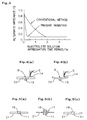
- Fig. 3 shows an example of the results in which a relationship between the electrolyte solution impregnation time period and the change in alternate impedance has been checked, in the frequency of 100 Hz, in the respective cases of the electrolyte solution filling method from the lower portion of the internal electrode body according to the present invention and the conventional electrolyte solution filling method from the upper portion as shown in Fig. 17.
- the electrolyte solution impregnation time period denotes a period of time to hold the vacuum atmosphere after commencement of injection of the electrolyte solution under vacuum atmosphere.
- the internal electrode body used in this test was produced by winding the positive electrode substrate having the width of 200 mm and the Length of 3600 mm, and the negative electrode substrate having the width of 200 mm and the length of 4000 mm, and it was housed in a battery case having an internal diameter of 48 mm ⁇ .
- a solvent a mixture of EC and DEC in an equal quantity was used.
- the air in the interior of the globe box, etc. is purged with an inert gas such as nitrogen or argon, and thereafter, excessive electrolyte solution remaining inside the battery 10 is extracted outside by using the nozzle 12.
- an inert gas such as nitrogen or argon
- the tip of the nozzle 12 is preferably inserted so as to reach the bottom portion inside the battery 10.
- the electrolyte solution will flow into this recessed portion 8, and thus, the remaining excessive electrolyte solution will be able to be extracted to a further extent.
- the recessed portion 8 may be formed by inflating the cap 22 so as to protrude outward around its center portion.
- a case in a shape of cylinder having a bottom is used as a battery case so that insertion of the internal electrode body therein and assembly of the battery will become easy.
- a recessed portion can be provided in the bottom portion of the cylinder-shaped case having a bottom in the first stage.
- the electrolyte solution injection opening 11 in the globe box, etc. is sealed. If this sealing work can be done with a simple and convenient method, a small-sized globe box corresponding to the size of the battery 10 can be used as a globe box, etc. In addition to that, a device to seal the end portion of the battery 10 is not required to be disposed in the globe box, reduction in facility costs and reduction in quantity of purge gas for use can be attained.
- the electrolyte solution injection opening 11 is preferably capable of being blocked with a simple and a convenient sealing method such as use of setscrew from outside or pressure fitting or use of filling-in sealing material.
- the screwing can easily be carried out, as shown in the sectional view of Fig. 5(a), by forming the electrolyte solution injection opening 11 in the shape of a screw, and setting a screw 16 having a complementary shape thereto for fixing.
- a screw processing portion 17 where screw is formed may be provided on one or both surface(s) of the cap 21 to set with a screw 16 in a complementary shape.
- pressure fitting may be performed by fitting a plug under pressure, into an electrolyte solution injection opening 11 having a slight inclination in such a manner that its diameter becomes gradually smaller as goes inside the battery, a metal component 18, etc. which is fitted in with the shape of said opening, as shown in the sectional view of Fig. 5(c).
- the electrolyte solution injection opening 11 can also be sealed with a metal wax fused by partial heating.
- the battery is completed, but, here as for the use of the formed battery, a consideration is given to the one to drive the motor of such as an EV or an HEV, etc.
- a voltage such as 100 V to 200 V is required to drive a motor, thus a plurality of batteries is required to be connected in series.
- Fig. 6 shows a sectional view of another embodiment of the battery structure according to the present invention.
- the electrolyte solution injection opening 11 is formed in the center of the cap 21 forming one end surface of the battery 10, and a pole-shaped external terminal 15 is disposed in the cap 21 in such a position that the electrolyte solution injection opening 11 is not obstructed thereby.
- any suitable shape may be designed.
- the present invention is not limited to the above-described embodiments.
- a core having section of practically circular shape is used in the above-mentioned embodiments.
- the electrolyte solution injection opening can be disposed in a position on the extended line of the through hole of the core.
- the present invention is not applied only to cylindrical batteries, but also to all the other batteries using cores having through holes.
- a battery structure of the present invention having the battery structure to make the above-described electrolyte solution filling method easy as well as contributing to improvement of battery performance even in the case where a single battery is adopted.
- the internal terminals 14 and the tabs 5 connected to the internal terminals 14 as well are preferably installed, as shown in Fig. 1, in a remote position from the regions located along the common line extended from the core 6 in the axial direction (in the longitudinal direction) of the core 6, namely, the region 98 which covers from the electrolyte solution injection opening 11 to the upper end of the core 6 and the region 99 which covers from the lower end of the core 6 to the cap 22 at the bottom party of the battery 10.
- the internal terminals 14 and the tabs 5 are disposed so as not to hinder the take-in and -out of this nozzle 12.
- the regions 98 and 99 may be a region within an extended line from the through hole 7 in its axial direction in a strict sense, but there are no problems in taking the regions 98 and 99 to a broad extent as described above.
- the internal terminals 14 are not disposed respectively at each one site in the caps 21 and 22 as shown in the battery 10 in Fig. 1, but may be disposed at two sites in one cap 21, and moreover, three or more may be disposed. Moreover, the following is to explain the battery structure that has been contemplated with attention having been paid to the positions to dispose such internal terminals.
- Fig. 7 is a plan view looking at the core 6 from the axial direction (the longitudinal direction) which shows an embodiment of the suitable mounting sites 9 of the tabs 5 in the internal electrode body 1.
- the tabs 5 are preferably disposed at an approximate equal distance so that each tab 5 may collect electricity from a constant area, but here further, as shown in Figs. 7(a) and 7(b).
- the attachment sites 9 of the tabs 5 are positioned in an approximately straight line X in the direction of diameter from the outer circumference of the core 6 to the outer circumference of the internal electrode body 1, thereby the improvement in implementation efficiency in the case where the tabs 5 are collectively connected with the internal terminals 14 is attained. Thus, it is preferable.
- the tabs with minimum necessary length can reduce the resistance of the tabs themselves.
- the attachment positions 9 of the tabs 5 should be not necessarily on the straight line X. That is, the tabs 5 may be attached at any position apart from the straight line X toward the straight line Y which crosses at the right angle with the straight line X on the end surface of the internal electrode body 1, as far as they may be positioned within such a range that the collective connection of the tabs 5 is not hampered.
- Fig. 8 is a sectional view looking at one embodiment of the attachment position of the internal terminals 14 from the direction of the straight line Y crossing with the straight line X at the right angle wherein the tabs 5 are attached as shown in Fig. 7.
- Fig. 8(a) corresponds to Fig. 7(a) and Fig. 8(b) to Fig. 7(b), respectively.
- At least one internal terminals 14 collectively connected with the tabs 5 are disposed on one surface of the cap 21 which is a member for forming the end surface of the battery, so that its collective connection portions 44 are placed in the position which is an outward-extended range from the outer circumference of the core 6 to the outer circumference of the internal electrode body 1 in the axial direction of the core 6, i.e. within the range D.
- those with one collective connection portion 44 being disposed to connect a plurality of tabs 5 at one site together in one internal terminal 14 are suitably used.
- the outer terminal 15 is disposed on the other surface of the cap 21.
- the tabs 5 in the same shape from the point of view of producing the battery at the time when the internal electrode body 1 is formed.
- this uniform shape is also preferable since the current can be expected to flow easily and evenly since the fluctuation in the resistance of the tabs 5 does not occur and the battery reaction takes place evenly.
- the internal terminal 14 is disposed especially in the center portion even within the range D; in other words, if the collective connection portions 44 are placed within an outwardly-extended position of the central portion in the direction of diameter from the outer periphery of the core 6 to the outer periphery of the internal electrode body 1, it is preferred that the resistance is reduced, when compared with the case where the collective connection portions 44 are disposed in the center portion or outer periphery portions: for the absolute length of the tabs 5 is shortened in the above-mentioned case.
- the length thereof is determined in such a manner that, by taking, as a standard, the length of the tab attached to the most remote site from the collective connection portion 44, a little allowance is given to the length in an extent that the battery assembly is not obstructed due to the relatively limited length. Even in this case, if the collective connection portion is placed within the range D, as is done in the present invention, there is still an advantage that this standard length of tab may be short, compared with the case where the collective connection portion 44 is not within the range D. Thus, short and low-resistant tabs become available.
- the shape of the internal terminal 14 does not matter, and connection points between the internal terminal 14 and the cap 21 can be changed variously according to the shape of the internal terminal 14.
- the collective connection portion 44 being the part to collectively connect the tabs 5 with the internal terminal 14 is disposed within the range D.
- an internal terminal 14 in a simple shape is preferably used considering the costs of internal terminals 14 themselves and their easy attachment onto the cap 21, etc.
- a plurality of internal terminals 14 is disposed so as to reduce easily the current collection resistance from the internal electrode body 1.
- the attachment sites 9 of the tabs 5 are disposed not only on the straight line X but also on the straight line Y, thereby the installment of four internal terminals 14 becomes possible with a great easiness.
- the tabs 5 are collectively connected with the internal terminals 14 with welding or caulking or eyelet so as to preferably enable to suppress the fluctuation of contact resistance in the collective connection portions 44. Since aluminum and copper are apt to form oxide films on their surfaces, there are cases where these oxide films give rise to large difference in contact resistance between each tab 5 and the internal terminal 14 if these materials are used in these tabs 5 and internal terminals 14. Therefore, when the tabs 5 are collectively connected with the internal terminal 14 with caulking or eyelet, the implementation preferably undergoes by applying pressure sufficiently high so as to destroy the oxide film, without giving no damage onto the tabs 5.
- the length of the core 6 is set approximately equal to the width of the positive electrode 2, and the like.
- the movement of the internal electrode body 1 within the inside of the battery case is suppressed by the necked portions 24 formed in the pipe 23.
- the improvement in the anti-vibration property is further strengthened by the fixation of the internal electrode body 1. At this time, of course, it is necessary to give consideration so that the method for filling an electrolyte solution according to the present invention can be easily carried out.
- the number 4 stands for an separator
- the number 5A stands for the tabs attached to the positive electrode 2 (positive tabs 5A)
- the number 5A stands for the tabs attached to the negative electrode 3 (negative tabs 5B), respectively for the clarification purpose.
- Fig. 10 is a sectional view showing one embodiment of the battery structure using such an internal electrode body 40.
- the tabs 5A for the positive electrode as well as the tabs 5B for the negative electrode being attached to the both ends of the internal electrode body 40 are connected with the internal terminals 74A and 74B, respectively.
- the internal terminals 74A and 74B are respectively attached to the caps 71A and 71B in advance, and that, at the same time, the external terminals 73A and 73B are preferably attached to another surface of the caps 71A and 71B where the internal terminals 74A and 74B are respectively disposed. Note that there will be nothing wrong with collective connection of the tabs 5A and 5B due to the employment of such a configuration as mentioned above.
- the internal terminals 74A and 74B are attached to the caps 71A and 71B so that their collective connection portions are placed within an outwardly-extended range in the axial direction of the core 41 from the outer circumference of the core 41 to the outer circumference of the internal electrode body 40.
- the tabs 5A and 5B are attached to the outer circumference portions of the caps 71A and 71B, over all length of the tabs 5A and 5B can be shortened to reduce resistance and thus can give rise to improvement in the performance of the battery.
- the internal electrode body 40 to which the caps 71A and 71B, etc. are attached is inserted inside the cylindrical-shaped battery case (pipe) 72.
- an insulating film 79 is disposed to secure insulation against the internal electrode body 40. But, in the case where the entire outer periphery of the internal electrode body 40 is covered with the separator 4, the insulating film 79 is not necessarily required in the portion of the outer periphery of the internal electrode body 40.
- the clearance between the outer periphery of the internal electrode body 40 and the inner surface of the battery case 72 is preferably small to an extent that it is not difficult to insert the internal electrode body 40 into the pipe 23, and further preferably, after the completion of assembling the battery, the internal electrode body 40 is preferably designed so as to receive compression stress from the battery case 72.
- the battery case 72 is subjected to processing for forming a necked portion, while the internal electrode body 40 is inserted into the battery case 72, to form the necked portions 81 which is protruded to the inner periphery party, at the vicinity of the end surfaces of the internal electrode body 40 and between the caps 71A and 71B, taking the length of tabs 5 and the core 41 into consideration.
- the forming locations of the necked portion 81 not only suppress the movement of the internal electrode body 40 but also play a role to determine the fixing positions of the caps 71A and 71B.
- the end portions of the battery case 72 is subjected to the caulking processing by utilizing the formed neck portion 81, with inserting the sealing material 82 between the caps 71A and 71B and the battery case 72, respectively.
- the battery case 72 is sealed at its both ends, and the core 41 is fixed in a state that it is sandwiched between the caps 71A and 71B.
- the core 41 may be fixed, depending only on the pressure simply given by the caps 71A and 71B, however, it is preferred that the core 41 is held to fix by virtue of a plurality of grooves, protrusions or the like is preferably formed in the caps 71A and 71B in such a form that it is a complementary one with the shapes of the end portions of the core 41 after assembling the core and the caps into one in a right way by using a locating means mentioned above.
- the movement of the internal electrode body 40 in the axial direction of the core 41 will be suppressed by the thus formed core 41.
- the movement of the internal electrode body 40 in the longitudinal direction of the core 41 is also suppressed by the necked portion 81 in a supplementary fashion, and its movement in the direction of diameter is suppressed by the battery case 72 and the insulating film 79. Therefore, compared with the conventional batteries, movements of the internal electrode body 40 within the case in the longitudinal direction and the direction of diameter are suppressed extremely well, which results in a remarkable improvement in anti-vibration performance.
- peeling of the electrode active materials is suppressed, and the stress which has been applied to the tabs 5A and 5B due to vibration, etc. of the internal electrode body 40 is advantageously reduced and the like, thus the long durability of the battery will be attained.
- the sealing material 82 a polymer material having a superior anti-corrosion property against electrolyte solutions, and good sealing performance capable of preventing leakage of electrolyte solutions by processing with caulking may be used.
- the polymer material includes polyethylene, polypropylene, ethylene-propylene-elastomer, styrene-type elastomer, olefin-type elastomer, ethylene-propylene rubber, butyl rubber, styrene-butadiene rubber, and fluororubber.
- metal materials are suitably used for the caps 71A and 71B, and since the core 41 contacts the caps 71A and 71B, as the core 41, those made of insulating materials, or those coated with insulating materials on the surface of the metal materials are suitably used.
- an insulating material a resin such as polypropylene and a phenolic resin such as bakelite(a registered trademark), or the like, and a ceramic such as alumina, or the like may be illustrated.
- a metal material aluminum, copper, stainless, or the like may be illustrated.
- the core 41 may be any material as far as such a material has at least the end surface made of an insulating material.
- the positive electrode 2 and the negative electrode 3 are wound around outer periphery of the core 41 so as to be insulated against the core 41.
- the aforementioned method for filling an electrolyte solution of the present invention may be applied to the battery 50 if hollow cylinder-shaped core is used as the core 41, and the electrolyte solution injection opening 77 is provided on either one of the caps 71A and 71B (the cap 71A in Fig. 10) in the outwardly-extended position of the hollow portion of the core 41 at the time of sealing the both ends of the battery case 72.
- Fig. 11 is a perspective view showing a suitable embodiment of the core 41. Note that it is preferred to form holes 42, slits 43, or the like at the end portion of the core 41.
- the battery case 72 both ends of which are sealed is placed in a reduced atmosphere, and through the electrolyte solution injection opening 77, the tip of the nozzle for electrolyte solution injection is inserted until it reaches around the opposite end surface (the lower portion of the battery 50), and a predetermined quantity of electrolyte solution is injected and the impregnation process is carried out adequately. And after the interior atmosphere thereof is replaced by an inert gas, the nozzle for electrolyte solution injection is used as the nozzle for extraction to extract unnecessary electrolyte solution remaining in the lower portion of the battery 50 and the hollow portion of the core 41. Finally, under the inert atmosphere, the electrolyte solution injection opening 77 is sealed by using a screw or the like to complete the assembly of the battery 50.
- a sectional view showing another embodiment of the battery according to the present invention is shown in Fig. 12.
- the internal electrode body a conventional-type internal electrode body 1, shown in Fig. 18, which comprises the core 6 having a length of being almost equal to that of the positive electrode 2, or that of the negative electrode 3, and having a positively protruded portion; and the insulating members 75 which is disposed so as to extend the length of the core 6 at the both ends, that is, the one wherein the insulating members 75 are used, and at the both ends of the core 6.
- the core 6 as well as the insulating members 75 are configured to be sandwiched between the caps 71A and 71B which are used to seal the end surface of the battery case 72 and be fixed.
- an insulating members 75 with portions having different thickness in the outer diameters formed by changing the thickness of the members is inserted, as shown in Fig. 12, to the hollow portions of the core 6, from the side of the portions with shorter outer diameter; or the core 6 with concave-convex portions 76 at the end portions is used, and the insulating members 75 having the end shapes to engage with these concave-convex portions 76 is inserted thereto as shown in Fig. 13.
- an insulating resin such as polypropylene and a phenolic resin such as bakelite(a registered trademark), and the like, and ceramics such as alumina, and the like are preferably used.
- the internal electrode body 1 which has the core 6 extended with the insulating members 75 enables to form the battery 60 using the forming method similar to that in the case of the aforementioned battery 50. That is, the aforementioned method for filling electrolyte solution according to the present invention may be suitably used by providing the electrolyte solution injection opening 77 at the outwardly-extended position of the hollow portions of the core 6 and the insulating member 75 on one cap, for example, the cap 71A, as far as the core 6 and the insulating member 75 are hollow cylinder-shaped as shown in Fig. 13. In this case, hole portions or slits similar to the hole portions 42 or slits 43 shown in Fig. 11 are preferably provided in the insulating members 75 as shown in Fig. 13, in particular, the end parties contacting the caps 71A and 71B of the insulating members 75.
- a battery is usually provided with a pressure release valve at the end portion of the battery as a safety mechanism for preventing accidents such as a burst of the battery caused from the rise of a battery's internal pressure due to evaporation of electrolyte solution in the case where the battery temperature rises by over-charging or over-discharging.
- Figs. 14(a) and 14(b) are plan views of the end surface of the battery 50 from the longitudinal direction of the battery 50. That is, as shown in Fig. 14 (a), if a groove 85 which is thin in the thickness is formed on the cap 71A, and the external terminal 73A and the internal terminal 74A are provided on a position located within the inside of the groove 85, the groove 85 will function as a pressure release valve. This is because the groove 85 is tore to act as a pressure release means since the groove is weakened in the mechanical strength when the internal pressure of the battery rises, thereby the internal pressure of the battery is released to the atmospheric pressure.
- a metal foil 83 only bursts and the internal pressure of the battery will be released to the atmospheric pressure when the internal pressure of the battery rises; this is because, if a hole portion 86 is provided in a portion of the cap 71A and a metal foil 83 is attached thereto with welding, bonding, or the like so as to seal this hole portion, the metal foil 83 will function as a pressure release valve.
- the present inventive method for filling an electrolyte solution and the present inventive battery structure as well are explained, and the present invention is suitably applied to the assembly of batteries having a comparatively large capacity of, in particular, 2 Ah or more.
- the present invention can also be applied to batteries having a capacity smaller than the battery mentioned above, using wound-type internal electrode body.
- the battery according to the present invention can be suitably used as a motor-driving power source for an EV, an HEV, or the like. This is because it has a simple battery structure to assemble it easily, and moreover, the reduction in weight is attained due to a limited number of parts. Furthermore, it is featured with superior anti-vibration performance.
- the electrolyte solution can be injected simply.
- there can be brought remarkable effects such as the reduction in the production cost, the stability in the performance of the electrolyte solution and consequently stability of the performance of the battery.
- excessive electrolyte solution can be extracted and be reused, which will make production cost cut attainable.
- the quantity of excessive electrolyte solution remaining inside the battery can be minimized, thus leakage of the electrolyte solution, and corrosion, due to electrolyte solution, of various components disposed inside the battery will become preventable.
- the internal electrode body is fixed firmly inside the battery according to the battery structure of the lithium secondary battery of the present invention, the movement or deformation of the internal electrode body due to vibration hardly takes place and excellent anti-vibration performance can be obtained, remarkably contributing to the improvement in the reliability and the long durability of the battery life. Furthermore, since the position for disposing the internal terminal is optimized, the resistance of the tabs itself is reduced, and the fluctuation of the resistance among tabs can be reduced to a smaller level, there are attained remarkable effects such as the homogeneity of the battery reaction, the long durability of the battery life, and the easy discharge of a large current. In addition, there is an advantage that a plurality of internal terminals is easily disposed, and the current collection resistance from the internal electrode body may easily be reduced.
- a method for filling an electrolyte solution and a battery structure of a lithium secondary battery comprising an internal electrode body formed by winding a positive electrode, and a negative electrode, with sandwiching a separator therebetween around the outer periphery of a core, and an electrolyte solution to impregnate said internal electrode body; said method being excellent in the productivity, and battery performance as well, and being characterized by an easy filling of an electrode solution, with minimization of excessive electrode solution in the battery, by virtue of the provision of an electrolyte solution injection opening in a specific position, through which the electrolyte solution is injected and extracting efficiently by using a nozzle for injection and/or extraction of electrolyte solution.
Abstract
Description
- This invention relates to a method for filling an electrolyte solution into a lithium secondary battery; said method capable of filling electrolyte solution into a case and extracting an excessive electrolyte solution therefrom, and sealing easily a battery, thereby the simplification of fabrication process, the reduction in the production cost, and the improvement in compaction of energy density can be achieved, and a battery structure of the lithium secondary battery; said battery having a reduced current collection resistance from positive electrodes and negative electrodes, and a narrowed deviation in the fluctuation in the resistances among the tabs engaged in current collection as well, and having a simple structure as a battery so as to enable to make an easier assembly of the battery and to effectuate the aforementioned method for filling an electrolyte solution into the case easily.
- In recent years, the lithium secondary battery has been widely used as a power battery for handy electronic appliances such as personal handy phone systems, video tape recorders, notebook-type computers, or the like. Additionally, in the case of a lithium secondary battery, a single battery can generate a voltage of approximately 4 V, and this level of voltage is higher than that of conventional secondary batteries such as a lead battery, or the like, and its energy density is also high. Thus, much attention has been paid to it not only as a power source for the aforementioned handy electronic appliances, but also as a motor driving power source for an electric vehicle (EV) or a hybrid electric vehicle (HEV), of which penetration among the general public is being earnestly planned as a low-pollution vehicle due to the recent development in the environmental problems.
- In a lithium secondary battery, in general, a lithium- transition metal compound oxide as a positive active material, a carbon material as a negative active material, and an organic electrolyte solution obtained by dissolving a Li-ion forming electrolyte in an organic solvent as an electrolyte solution are used. And, for an internal electrode body as a portion where battery reaction is carried out, are available various types.
- For example, in a coin-shaped battery with a small capacity, a sandwiched-type internal electrode body in which a separator is sandwiched between a positive electrode and a negative electrode is used. Here, as the positive electrode and the negative electrode, those that are formed in a disk like shape, or in a coin like shape by subjecting positive material and negative material to press-forming processing or the like, respectively are suitably used.
- As one example of preferable structures of internal electrode bodies to be used for a lithium secondary battery with a comparatively large capacity usable for an EV, or the like, as is shown in Fig. 18,there is given a wound-type
internal electrode body 1 being formed by winding around the outer periphery of a hollow cylinder-shaped core 6 apositive electrode 2 having atab 5 for current collection and anegative electrode 3 havingtab 5 for current collection, in a such manner that thepositive electrode 2 andnegative electrode 3 are not brought into direct contact with each other, by sandwiching aseparator 4 between thepositive electrode 2 and thenegative electrode 3. Here, in general, the length of thecore 6 is set equal to the width of thepositive electrode 2 and that of thenegative electrode 3. Incidentally, there is also proposed a battery using a laminate-type internal electrode body formed by laminating alternately via separators 4 a plurality ofpositive electrodes 2 andnegative electrodes 3 having been prepared by cutting the above-mentioned positive and negative electrodes, respectively into those with small areas. - Now, in any case where any of the above-described structures is adopted as an internal electrode body, it is necessary to soak the internal electrode body in an electrolyte solution. Here, as an electrolyte solution, a non-aqueous electrolyte solution (hereinafter to be referred to as an "electrolyte solution"), which is obtained by dissolving a lithium electrolyte in an organic solvent, is used. In the case of a coin-shaped battery, for example, there is employed such a technique that a predetermined quantity of an electrolyte solution is injected by using a metering pump, or the like, under a reduced atmosphere and the battery case is sealed so as to fill the case with the electrolyte solution, after the internal electrode body is mounted inside a battery case. In addition, even in the case where a wound-type internal electrode body is used, a similar technique is used as long as a small capacity battery such as common 18650 (with a diameter of 18 mm⊘ and a length of 65 mm) cylinder-type battery is produced. In such a method, an excessive amount of electrolyte solution that is not actually required is liable to be filled therein.
- Since electrolyte solution is generally expensive, the percentage of battery costs attributable to electrolyte solution is not small. Nevertheless, in the case of those batteries having a small capacity, the reasons why the aforementioned method for filling an electrolyte solution is adopted are considered that:
- the space where excessive electrolyte solution (hereinafter to be referred to as a "excessive electrolyte solution") is filled in is small in the absolute value, the cost for the electrolyte solution used for filling such a small space is considered not to be so high since the internal electrode body does not occupy much space in the interior of the battery in a small capacity battery;
- a desired battery performance is obtainable if a minimum required quantity of an electrolyte solution is filled in a case since the area of reaction in the battery is small; and
- an introduction of a step for recovering an excessive electrolyte solution results in raising production costs unintentionally, etc.
-
- On the contrary, in the case of a battery having a relatively large capacity (hereinafter to be referred to as a "large capacity battery") to be applied to an EV, or the like, the size of a battery itself will necessarily become large. In such a case, the use of the wound-type
internal electrode body 1 shown in Fig. 18 requires a larger space for housing thecurrent collection tabs 5 at both ends or one end of the case for the battery. Additionally, since a hollow cylinder-shaped type core is generally used for thecore 6, the absolute volume to be occupied by these spaces inside the case for battery becomes large. - Accordingly, if an electrolyte solution is filled into a case for a large capacity battery by using a technique similar to that for the above-described small capacity battery, an expensive electrolyte solution is used not in an economic manner. This would bring the increase in the production cost and the reduction in the energy density of the battery, as well. Furthermore, it is not preferable, from the viewpoints of durability, to keep it such a state that metal members other than the internal electrode body, sealing members of the battery case, and the like, are always in contact with the electrolyte solution since it causes often the leakage of the electrolyte solution, the corrosion of said members, or the like.
- On the other hand, the electrolyte solution is required to fill in an amount sufficient to impregnate the internal electrode body properly even in the case of a large internal electrode body having a large battery area. And in the case where this is not fulfilled, not only the desired battery performance cannot be attained, but also the fluctuation in the performance of respective batteries will take place. Accordingly, in the case of a large capacity battery, it is preferable to impregnate the internal electrode body thoroughly in an excessive amount of an electrolyte solution under a reduced atmosphere, and thereafter the excessive electrolyte solution is removed.
- Therefore, in a large capacity battery, if one wants to fill an electrolyte solution by employing a technique similar to that for a small capacity battery, the following steps would be given as an example;
- as shown in Fig. 17, at first, a case for
battery 65 with oneend portion 61 having been sealed is disposed in a globe box or the like with that sealedend 61 being placed downward, - then an electrolyte solution transferred from another
end portion 62 of the case which is open at the upper portion with a metering pump or the like is injected by using anozzle 63 or the like after reducing the atmosphere of the globe box in such a manner that the electrolyte solution is injected intermittently until the liquid surface does not go down so as to subject the internal electrode body to the impregnation treatment with the electrolyte solution for a predetermined period of time, - the interior of the globe box or the like is purged with inert gas,
- thereafter the excessive electrolyte solution is drained by putting
the case for
battery 65 upside down, and - finally the
end portion 62 which has been left open is sealed. -
- However, in the case of such a method that an electrolyte solution is supplied from the upper portion of the case for the battery, the impregnation of an electrolyte solution starts mainly from the upper portion of the internal electrode body under a reduced atmosphere. Therefore, bubbles generated in the lower portion of the internal electrode body will hardly be liberated form the upper portion of the case for the battery. Accordingly, it will require to hold the resultant for a long period of time under reduced atmosphere. In this case, if an organic solvent being highly volatile is solely used for an electrolyte solution, the evaporation of the solvent will bring a problem that the density of electrolyte fluctuates from product to product. In addition, in the case where a highly volatile organic solvent is mixed with other non-volatile solvent or the like for use, the predominant evaporation of the volatile organic solvent causes the deviation in mixing ratio from product to product. This would bring a problem that the density of the electrolyte fluctuates from product to product. Anyhow, in any one of these cases, the full extent exertion of the performance of electrolyte solution cannot be expected.
- Moreover, in case of a large capacity battery, due to a big shape of the battery itself, the sealing of an open end of the case for the battery within the globe box or the like would bring various problems. That is, an enlargement of the globe box or the like is required since a sealing device should be installed within the globe box or the like. Furthermore, the enlargement of the globe box results in the decrease in the degree of the reduction of the interior pressure thereof the enlargement of the vacuum pump, and the mass consumption of purge gas or the like. Thus, it is not realistic.
- Therefore, the present inventors have extensively studied, in particular, the simplification of a method for filling an electrolyte solution in the production of a large capacity battery. As a result, they reached the present invention to be described later. Moreover, various studies have been made at the same time so as to find out not only a battery structure suitable for using the method filling an electrolyte solution according to the present invention, but also a battery structure capable of improving the battery performance and productivity even in the case where the method for filling an electrolyte solution according to the present invention is not used.
- One of the problems to be solved is the reduction in current collection resistance from the internal electrode body and the reduction in difference in current collection resistance of each tab. A tab is connected directly with an external terminal of the battery, that is, directly with an electrode terminal to extract current out from the battery, or is connected with an internal terminal thereof, that is, a terminal to which the tabs are intermediately connected collectively inside the battery. Accordingly, in the case where the tabs are connected with the internal terminal, it is necessary that the internal terminal is made conductive to the external terminal to form a current path between the tabs and the external terminal.
- As a method for forming the conductive state between the tabs and the external terminal, there is proposed, for example, in JP-A-9-92338, a lithium
secondary battery 27 in which a series of flexible leads (equivalent to "tabs" in meaning) 37 is sandwiched between theelectrode terminal 38 and the hold-down hardware 33, with forming a warping shape as shown in Fig. 16; said leads 37 being welded to theelectrode terminal 38 by laser beam. In this lithiumsecondary battery 27, theelectrode terminal 38 is attached to a cap (ceiling plate) 29 by using anut 34, and thecap 29 is provided with not only electrolyte solution injection opening 32 which is to be sealed with ablank cap 30 but also apressure release valve 26. - However, in case of the lithium
secondary battery 27 disclosed in the JP-A-9-92338, theleads 37 may be sandwiched with the hold-downhardware 33 at any position of the outer periphery of theelectrode terminal 38,as a corollary, theleads 37 disposed in the inner periphery of theinternal electrode body 35 becomes long, and, on the contrary, theleads 37 disposed in the outer periphery becomes short. In this case, since the quantity of current flow in eachlead 37 is different due to the difference in resistance of eachlead 37, depending upon its length, there is a fear that the uniformity in the battery reaction cannot be maintained when used as a battery for an EV which requires the frequent flow of a large current. - In addition, since the
leads 37 may be attached to any position of the outer periphery of theelectrode terminals 38 with laser welding, and the structure at the end portion of the battery is complicated and various parts are installed therein, as shown in Fig. 16, thus the work efficiency (productivity) of the battery assembly is considered to be not necessarily good. - Moreover, a
battery 27 disclosed in JP-A-9-92338 has the configuration at its both ends, as shown in Fig. 16. It is stated in the laid-open invention that the injection of electrolyte solution is carried out by injecting electrolyte solution from one end of the injection opening 32 for electrolyte solution, while keeping the interior of thebattery 27 is under a reduced pressure by deaerating from the other end of the injection opening 32 for electrolyte solution, and this step should be repeated several times. However, it is not advantageous to assemble a battery with the repetition of such steps several times. Moreover, it is not advantageous to provide the both ends with theinjection openings 32 for electrolyte solution which eventually will be sealed since the leakage of the electrolyte solution and the decrease in air tightness are liable to occur. - Furthermore, the battery disclosed in JP-A-9-92338 has been proposed to prevent damage to leads 37 under severe vibrations when the battery is used as for the battery for an EV. Therefore, it proposes to use a flexible material for
lead 37. At the same time, it refers to the reduction in internal resistance by virtue of a broadened welded portion between theleads 37 and theelectrode terminals 38 formed by laser welding, however, it is quite silent about the reduction in fluctuation in the resistance among respective leads 37. - Another problem is how to secure the durability against vibration during driving since the durability is an essential requirement in the case of a battery for an EV. For example, when the internal electrode body vibrates or moves inside the battery case, there is a fear that the electrode active materials coated on the positive electrode and the negative electrode are peeled, thereby the battery capacity is reduced. Furthermore, it is not preferable since there is a fear that the formation of the short circuit between the positive electrode and the negative electrode due to the peeled electrode active materials. Moreover, the end surface of the internal electrode body is apt to be deformed from an initial plain shape into a shape such as spiral waves or the like due to vibration, and such a deformation of the internal electrode becomes a cause of an unfavorable uneven battery reaction.
- Therefore, there is proposed, JP-A-9-92241, a
battery 28 having such a structure that, as shown in Fig. 15, anelectrode pole 25 having its lower surface covered withinsulator collar 39 is inserted into a hollow portion of acylindrical core 31 from which an electrode spiral body 36 (equivalent to the internal electrode body 1) is formed, and saidelectrode pole 25 is fixed to acap 29 with anut 34. In addition, there is proposed, in JP-A-1-175176, a battery structure that an internal electrode body formed by inserting a bar-shaped insulating body into a portion formed by using a tentative core which was removed thereafter is housed in the battery case. - However, in the case of the
electrode spiral body 36 proposed in JP-A-9-92241, the inner periphery surface of thebattery case 19 and theelectrode pole 25 function only as a stopper so as to suppress the movement of theelectrode spiral body 36 in the diameter direction. However, it does not suppress the movement in the diameter direction, and it has such a structure that the movement in the longitudinal direction of theelectrode spiral body 36 take places easily in the distance of the gap with theelectrode pole 25. If the movement to the longitudinal direction of theelectrode spiral body 36 takes place, theelectrode spiral body 36 collides with theelectrode pole 25, which would damage the leads 37 (equivalent to tabs 5) attached on the end surfaces of theelectrode spiral body 36. Moreover, it is considered that it is liable to receive such damages that the electrode active material is peeled, etc. at the end portions of theelectrode spiral body 36. - Furthermore, in case of the invention disclosed in JP-A-1-175176, it is not formed in such a structure that the movement of the longitudinal direction of the internal electrode body is suppressed. This is because the internal electrode body is fixed by pressure formed between a solid bar of an insulator inserted into the inner periphery surface of the battery case, and the core of the internal electrode body. Thus, no positive attempt has been made hitherto so as to suppress the movement to the longitudinal direction since much attention has been given to the fixation of the internal electrode body in the direction of diameter.
- The present invention has been made so as to solve problems of the prior art mentioned above. Thus, the present invention is aiming to keep at the minimum level as required the amount of the excessive electrolyte solution to be filled inside the battery on the occasion of forming a comparatively large capacity battery. Moreover, the present invention is aiming to provide a simply operative method for filling an electrolyte solution, and provide a battery structure capable of operating said filling method easily. Furthermore, the present invention is aiming at to attain the improvement in the battery performance such as reduction in current collection resistance and improvement of anti-vibration performance.
- That is, one of the aspects of the present invention is directed to a method for filling an electrolyte solution into a lithium secondary battery comprising an internal electrode body formed by winding a positive electrode, and a negative electrode, with sandwiching a separator therebetween around the outer periphery of a core, and an electrolyte solution to impregnate said internal electrode, which comprises the steps of :
- inserting a tip of a nozzle for injecting said electrolyte solution in such a depth that at least it reaches a position on an end surface of said internal electrode body located on another opposite side through a through hole of said core and an electrolyte solution injection opening being provided in an extended position of said through hole on one end surface of the battery, or an electrolyte solution injection opening being integrally formed with an external terminal in an extended position of the through hole of the core on one end surface of the battery,
- injecting the electrolyte solution until at least the internal electrode body is immersed, and
- thereafter extracting an excessive electrolyte solution remaining inside the battery outside by using a nozzle for extraction of electrolyte solution.
-
- The method for filling an electrolyte solution of the present invention is preferably used in a battery where the electrolyte solution injection opening is disposed in the center of one end surface of the battery and/or the core is disposed in the center of the battery. In addition, one nozzle may be used as a nozzle for injection of electrolyte solution and a nozzle for extraction of electrolyte solution as well. It is preferable to insert the tip of the nozzle for injection of electrolyte solution or that of the nozzle for extraction of electrolyte solution in such a manner that it reaches the other end of the battery to implement inject or extraction of electrolyte solution under this state. In this case, if a recessed portion is provided in the inner center of the other end of the battery, or if a recessed portion is provided by forming the center portion of the other end of the battery in a convex shape outward, an excessive electrolyte solution remaining in this recessed portion is easily extracted by a nozzle for extraction of electrolyte solution.
- After extraction of the excessive electrolyte solution, the electrolyte solution injection opening is enclosed from outside with screwing or pressure fitting or filling with a sealing material to implement sealing of the battery easily. Moreover, the assembly work of the battery becomes preferably good, if the electrolyte solution is extracted and/or injected by using a pipe as a body member of the battery case after the battery is sealed by subjecting the both ends of the pipe to caulking processing in order to occlude the ends of the pipe with the cap. The method for filling an electrolyte solution the present invention is suitably applied to a battery having the battery capacity of 2 Ah or more.
- Now, as a first embodiment of a battery structure according to the present invention, there is provided a battery structure of a lithium secondary battery comprising an internal electrode body formed by winding a positive electrode, and a negative electrode, with sandwiching a separator therebetween around the outer periphery of a core, and an electrolyte solution to impregnate said internal electrode body;
wherein an electrolyte solution injection opening is provided in an extended position of the through hole of the core on one end surface of the battery, or an electrolyte solution injection opening is integrally formed with an external terminal in an extended position of the through hole of the core on one end surface of the battery. - In this first battery structure, the electrolyte solution injection opening is preferably disposed in the center of one end surface of the battery and/or the core is preferably disposed in the center of the battery. In addition, it is preferable that the electrolyte solution injection opening preferably may be sealed from outside with screwing or pressure fitting or filling with a sealing material.
- In addition, as a second battery structure according to the present invention, there is provided a battery structure of a lithium secondary battery comprising an internal electrode body formed by winding a positive electrode, and a negative electrode, with sandwiching a separator there-between around the outer periphery of a core, and an electrolyte solution to impregnate said internal electrode body,
wherein the core is sandwiched between caps for sealing the end surfaces of the battery case, and is fixed. - And in this second battery structure, insulating materials or metal materials the surfaces of which are covered with insulating materials are preferably used as a core.
- Moreover, as a third battery structure according to the present invention, there is provided a battery structure of a lithium secondary battery comprising an internal electrode body formed by winding a positive electrode, and a negative electrode, with sandwiching a separator therebetween around the outer periphery of a core, and an electrolyte solution to impregnate said internal electrode body,
wherein insulating members are disposed at the both ends of the core to extend the length of the core, and the core as well as the insulating member are sandwiched between caps to seal the end surfaces of the battery case, and are fixed. - In these second and third battery structures where the core, and the like are sandwiched between caps, it is preferred to provide an electrolyte solution injection opening on one of the caps at the position extended from the hollow portion of the core or the insulating member. At this time, it is preferred that hole portions or slits are provided on the end portions of the core or the insulating members. It is also preferred to provide a recessed portion in the inner center portion of the end surface of a case for battery where the electrolyte solution injection opening is not formed. It is also preferred to provide a recessed portion by forming a convex shape outwardly on the center portion of the end surface. Incidentally, such an arrangement to provide a recessed portion is suitably applied to the first battery structure, too.
- Next, as a fourth battery structure according to the present invention, there is also provided a battery structure of a lithium secondary battery comprising an internal electrode body formed by winding a positive electrode, and a negative electrode, with sandwiching a separator there-between around the outer periphery of a core, and an electrolyte solution to impregnate said internal electrode body,
wherein one collective connection portion is provided in one internal terminal to connect a plurality of tabs together in one place, and the collective connection portion is positioned within an extended range in the axial direction of the core covering from the outer periphery of the core to the outer periphery of the internal electrode body. - In case of the fourth battery structure, it is preferred to provide one collective connection portion capable of connecting a plurality of tabs together in one place in one internal terminal; said collective connection portion being positioned within a range which is extended, in the axial direction of the core, from the outer periphery of the core to the outer periphery of the internal electrode body. Moreover, it is also preferred to form this collective connection portion in such a structure that a plurality of tabs provided so as to be positioned on an approximately straight line within a range, in the direction of diameter, which is extended from the outer periphery of the core to the outer periphery of the internal electrode body are collectively connected with one internal terminal. The internal terminal is suitably disposed in the caps sealing the end portions of the battery.
- Moreover, a plurality of internal terminals is preferably disposed for the positive electrode and the negative electrode, respectively. And the collective connection portions of the internal terminals are preferably placed in the extended position in the center direction of diameter from the outer periphery of the core to reach the outer periphery of the internal electrode body. The collective connection of tabs with the internal terminal is preferably formed by means of welding, or caulking, or eyelet. The material for the internal terminal is preferably produced from aluminum, aluminum alloy, copper or copper alloy. Incidentally, if the caps sealing the end portions of the battery can act as a path for electric current, the battery structure will not become complicated and is preferable.
- It is preferable to use commonly a battery case of which caps are employed as the end surfaces of the battery, in any of the above-mentioned first to fourth battery structures; said battery cases being preferably configured in such a manner that the caps are sandwiched between the end portions of the pipe, and the end portions of the pipe are sealed by caulking process. In addition, between an end portion of the internal electrode body and a cap, it is preferable to provide a necked portion in the inner periphery portion of the pipe so as to suppress the movement of the internal electrode body inside the battery. The battery structure of the present invention is suitably applied to a battery with battery capacity of 2 Ah and more, but there are no reasons to exclude application to a battery using a wound-type internal electrode body with a less battery capacity. In addition, the battery structure of the present invention can be suitably applied to a battery to be used as a motor driving power source for an electric vehicle or a hybrid electric vehicle.
-
- Fig. 1 is a diagram illustrating one of the embodiments of the present method for filling an electrolyte solution and that of the embodiments of the present inventive battery structures.
- Fig. 2 is an illustrative drawing of an example of method for measuring the period for the impregnation in the electrolyte solution.
- Fig. 3 is a graph showing a relationship between the period of impregnation time with electrolyte solution and the change of alternate impedance.
- Fig. 4(a) and Fig. 4(b) are a sectional view showing an embodiment of a cap of the bottom of a battery usable suitably for the present invention, respectively.
- Fig. 5(a), Fig. 5(b), and Fig. 5(c) are a sectional view showing an embodiment of electrolyte solution injection opening usable suitably for the present invention, respectively.
- Fig. 6 is a sectional view showing another embodiment of battery structure of the present invention.
- Fig. 7(a) and Fig. 7(b) are a plan view showing an embodiment of suitable attachment position of tabs of the present invention, respectively.
- Fig. 8(a) and Fig. 8(b) are a sectional view showing an embodiment of a place for disposing collective connection portion in the internal terminals in correspondence with the tab attachment position described in Fig. 7, respectively.
- Fig. 9 is a perspective view showing the structure of a wound-type internal electrode body usable suitably for the present invention.
- Fig. 10 is a sectional view showing a still another embodiment of the battery structure of the present invention.
- Fig. 11 is a perspective view showing an embodiment of a core usable suitably for the battery structure of the present invention.
- Fig. 12 is a sectional view showing a still another embodiment of the battery structure of the present invention.
- Fig. 13 is a perspective view showing another embodiment of a core usable suitably for the battery structure of the present invention.
- Fig. 14(a) and Fig. 14(b) are a plan view showing an embodiment of a pressure release valve being suitably disposed in the battery structure of the present invention, respectively.
- Fig. 15 is a sectional view showing an example of the end structure in the conventional lithium secondary battery.
- Fig. 16 is a sectional view showing another example of the end structure in the conventional lithium secondary battery.
- Fig. 17 is an illustrative drawing showing an example of the conventional method for filling electrolyte solution.
- Fig. 18 is a perspective view showing a general structure of a wound-type internal electrode body.
-
- Preferred embodiments of the present invention will next be described with reference to the drawings, however, it goes without saying that the present invention is not limited to those embodiments.
- In case of a lithium secondary battery of the present invention (hereinafter referred to as a "battery"), as is previously explained with referring to Fig. 18, there is employed a wound-type internal electrode body 1 (hereinafter referred to as an "
internal electrode body 1") which is formed by winding around the exterior circumference of a core 6 apositive electrode 2 and anegative electrode 3 to whichtabs 5 are respectively attached, with sandwiching aseparator 4 therebetween not so as to contact thepositive electrode 2 and thenegative electrode 3 directly with each other. - The
positive electrode 2 and thenegative electrode 3 are produced, respectively by coating electrode active material (hereinafter the term "electrode active material" means both positive active materials and the negative active material) on both sides of the respective electrode substrates; such electrode substrates (electricity collecting body) being a foil made of aluminum, titanium, or the like for thepositive electrode 2, and a foil made of copper, nickel, or the like for thenegative electrode 3. - The positive active material to be used for forming the
positive electrode 2 is not limitative, and a lithium transition metal compound oxide such as lithium cobalt oxide (LiCoO2), lithium nickel oxide (LiNiO2), lithium manganese oxide spinel (LiMn2O4), or the like is suitably used, and it is preferable that carbon fine powder such as acetylene black, or the like is added so as to improve conductivity. On the other hand, as a negative active material, an amorphous carbon material such as soft carbon or hard carbon, or highly graphitized carbon powder such as artificial graphite is used. - Coating of electrode active material onto these respective electrodes is carried out generally by coating, on both sides of the electrodes, a slurry or a paste which is prepared by adding a solvent, a binder, or the like to an electrode active material powder, by way of roll coater technique, or the like etc., and adhering the material thereon, thereby the
positive electrode 2 or thenegative electrode 3 is formed. - In addition, the
tabs 5 can be attached to a sideline of the electrode substrate by means of ultrasonic welding, or the like at the time when thepositive electrode 2 and thenegative electrode 3 are wound together with theseparator 4. At this time, thetabs 5 are preferably disposed at an approximately even distance so as to equalize the electricity collecting area of each tab. In many cases, the material of thetabs 5 is made the same as that for the electrode substrate to which thetab 5 is attached. - A cylindrical member having a through hole (or internal vacant portion) 7 is preferably used as a
core 6, and one prepared from any of various materials such as metals, resins, and ceramics, can be used if it has a sufficient mechanical strength and anti-corrosion resistance against an electrolyte solution to maintain the battery structure. - In addition, as the
separator 4, it is preferable to use a three-layer structural material in which a polyethylene film (PE film) having lithium ion permeability and micropores is sandwiched between a porous polypropylene films (PP films) having lithium ion permeability. This serves also as a safety mechanism in which when the temperature of theinternal electrode body 1 is raised, the PE film is softened at about 130°C so that the micropores are collapsed to suppress the movement of lithium ions, that is, the battery reaction. And by sandwiching this PE film between the PP film having a higher softening temperature the PP film maintains its shape and prevents the contact/short circuit between thepositive electrode 2 and thenegative electrode 3 even in the case where the PE film gets softened, and thus concrete control of the battery reaction and reservation of safety becomes possible. - As the electrolyte solution, it is suitable to use a non-aqueous organic electrolyte solution prepared by dissolving as an electrolyte at least one member selected from lithium fluoride complex compounds such as LiPF6, and LiBF4, and lithium halide such as LiClO4, etc., into an electrolyte solution selected from the group consisting of carbonate type electrolyte solutions such as ethylene carbonate (EC), propylene carbonate (PC), diethyl carbonate (DEC), and dimethyl carbonate (DMC),and organic solvents such as γ-butyrolactone, tetrahydrofuran, acetonitrile, and the like or a mixture thereof.
- The
internal electrode body 1 having been prepared from the above-described materials, and the like is housed inside the battery case in such a manner that conductivity between thetab 5 and the external terminal of the battery is secured, and theinternal electrode body 1 is impregnated in the non-aqueous electrolyte solution. And, thereafter, the battery case is tightly sealed. Incidentally, as will be described later, since the battery case made of a metal is suitably used, it is preferable that the outer periphery of theinternal electrode body 1 is configured to be covered by theseparator 4 in advance so as to attain insulation against the battery case when theinternal electrode body 1 is inserted in the battery case. In addition, it is preferable that the outer periphery of theinternal electrode body 1 is fixed with an insulating tape, etc., so that theinternal electrode body 1 is not dissolved. - Next, an embodiment of the structure of a battery to be formed as described above as well as the diagram illustrating the method for filling an electrolyte solution of the present invention is shown in Fig. 1. Here, a
pipe 23 is used as the body member of the battery case for thebattery 10, and those made of metals, such as aluminum, or stainless are suitably used. - Incidentally, while it is not shown in Fig. 1, in the case where the
metal pipe 23 is used, it is preferable to dispose an insulating film or a tube to be sandwiched between the internal surface of thepipe 23 and the outer periphery of theinternal electrode body 1 so as to prevent conductivity between theinternal electrode body 1 and thepipe 23 as well as the conductivity between thetab 5 and thepipe 23. Of course, as describe before, when the outer periphery of theinternal electrode body 1 is configured to be covered by theseparator 4, the insulating film or the tube is not necessarily required to be disposed between the internal surface of thepipe 23 and the outer periphery of theinternal electrode body 1. - After the
internal electrode body 1 is inserted into thepipe 23, anecked portion 24 is formed at a predetermined position (around the end portion of the internal electrode body 1) of thepipe 23 to suppress easily the movement of theinternal electrode body 1 in the longitudinal direction inside the battery. In addition, with thetabs 5 being connected with theinternal terminals 14 respectively mounted onto thecaps pipe 23 is subjected to caulking processing so that thecaps pipe 23, making use of the formednecked portions 24, thereby a battery case with the tight-sealed configuration can be easily formed. - Here, the term "internal terminal" 14 means a member which tentatively and collectively connects the
tabs 5 to extract electricity from theinternal electrode body 1. Therefore, aluminum, aluminum alloy, copper, or copper alloy is preferably used as a material for theinternal terminal 14. Incidentally, as theinternal terminal 14 in thebattery 10, a rivet-shaped one to which thetabs 5 are pressure-attached for connection is shown as an example, but there are no limitations on its shape. - In addition, the
caps internal terminal 14 such as aluminum or copper is suitably used, but an insulating material such as a hard resin or a ceramic may also be used. Accordingly, in the case where thecap 21 is made of a metal material, theinternal terminal 14 and theexternal terminal 13 necessarily become conductive and the current path is formed. In this case, the configuration of the end portions of the battery is made simple and improvement in terms of the battery assembly process is attained. On the other hand, in the case where an insulating member is used as thecaps internal terminals 14 and theexternal terminals 13 may be electrically connected through outer periphery of thecaps caps - It goes without saying that the
external terminal 13 is a member to be disposed outside thebattery 10 to extract the current of the battery outward, and there are no limitations on kinds of materials if a metal material is used. In the case where thecaps internal terminal 14 and theexternal terminal 13 are firmly attached to thecaps - Incidentally, in the
battery 10, a male screw configuration is used as the one of theexternal terminals 13, and a female screw configuration is used as the other thereof respectively. Adopting such a configuration is advantageous to the extent that a plurality ofbatteries 10 can be connected in series easily and firmly so as to minimize the contact resistance. - Incidentally, the
internal electrode body 1 is normally disposed at the center (it means the center in the diameter direction) of thebattery 10, and at this time, thecore 6 of theinternal electrode body 1 is necessarily disposed at the center of thebattery 10. Therefore, in thebattery 10, the electrolyte solution injection opening 11 is disposed in a position on the extended line of the throughhole 7 of thecore 6 in the cap 21 (thiscap 21 is placed at the upper party) forming one end surface. In addition, the electrolyte solution injection opening 11 is integrally disposed at the center portion of thecap 21 with theexternal terminal 13. - With the
battery 10 having the above-described configuration, the tip of the nozzle (hereinafter referred to as a "nozzle",) 12 to be used for the injection and/or the extraction of the electrolyte solution may be inserted so as to reach the other end of thebattery 10 through the electrolyte solution injection opening 11 and the throughhole 7. Incidentally, it is preferable to use onenozzle 12 for both of injection and extraction of the electrolyte solution, but a nozzle for electrolyte solution injection and a nozzle for electrolyte solution extraction may be used separately. - Now, the
battery 10 is placed in a space where atmospheric adjustment is possible, such as a globe box, when the electrolyte solution is filled in. As describe above, since the both ends of thebattery 10 have already been sealed with thecaps battery 10 after the injection of the electrolyte solution is completed. Accordingly, it is not necessary to place a device, etc. to implement the sealing work inside the globe box, etc., and thus, as the globe box, etc., a small-sized one in accordance with the size of thebattery 10 may be used. - When the air of the interior of the globe box, etc. is evacuated with a vacuum pump, the interior atmosphere of the
battery 10 necessarily becomes vacuum since thebattery 10 is provided with the electrolyte solution injection opening 11. Here, it is preferable to make a degree of vacuum of 0.1 Torr (13.3 Pa), or less. - Under this state, the tip of the
nozzle 12 is inserted through the electrolyte solution injection opening 11, and next through the throughhole 7 of thecore 6 to reach at shallowest the opposite other end (bottom) portion, in particular, the position of the end surface of theinternal electrode body 1, namely the position shown by the broken line AA' in Fig. 1, and thereafter, the electrolyte solution is injected to get at least theinternal electrode body 1 dipped, i.e., to reach the level shown by the broken line BB' in Fig. 1. Here, when the tip of thenozzle 12 is inserted to reach the deepest portion (the cap 22) in thebattery 10, a splash of the electrolyte solution is suppressed, and impregnation of the electrolyte solution can concretely start from the end surface at the bottom party of theinternal electrode body 1. - Incidentally, while impregnation of the electrolyte solution is under way, it is preferable to maintain a level of vacuum to such an extent that the electrolyte solution may not be boiled, and at this time the level of vacuum heavily depends on the property of the solvent consisting the electrolyte solution to be used. In addition, the
nozzle 12 may be inserted inside thebattery 10 in advance before the globe box, etc., is evacuated to become vacuum. A metal or a resin which is free of corrosion from the electrolyte solution is used as a material for thenozzle 12, and thenozzle 12 is connected with an electrolyte solution storage tank placed outside the globe box, etc. thorough a tube or a pipe, etc., and the electrolyte solution is transferred from the electrolyte solution storage tank, using a metering pump and the like. While it is not shown in Fig. 1, at the neck of thenozzle 12 or somewhere of the tube or the pipe, or the like, stop valves and the like are provided. - Thus, by filling the
battery 10 with the electrolyte solution from the lower portion, the electrolyte solution will impregnate theinternal electrode body 1 from the lower portion to the upper portion, and bubbles released from theinternal electrode body 1 can pass through the space where the electrolyte solution has not yet impregnated, thus, efficient impregnation of the electrolyte solution can become possible. Thus, the injection time of the electrolyte solution can be shortened, in the case of which its evaporation quantity can be controlled to the minimum to attain degradation of the electrolyte solution to be avoided even in the case where the electrolyte solution contains a solvent having a high volatility. - Incidentally, according the above-described method for filling an electrolyte solution, it is difficult to observe the surface level of the electrolyte solution visually in a conventional manner due to its tight-sealed configuration with an exception of the electrolyte solution injection opening 11. Under these circumstances, the total quantity to be injected of the electrolyte solution, as explained by referring to Fig. 17 before, is determined previously to the level that it corresponds to the lowest surface level when the internal electrode body is completely dipped in the electrolyte solution in the case where the electrolyte solution is injected into a battery with its upper portion being open.
- In addition, as shown in Fig. 2, the alternate impedance between the respective positive and negative
external terminals 13 provided for thebattery 10 is measured using animpedance analyzer 20 and the like, thus completion of impregnation of the electrolyte solution can be judged. But, in this case, a solvent consisting of only organic solvents without containing electrolyte is used as an electrolyte solution. Using such a solvent deprives an electrolyte from affecting the alternate impedance, and the alternate impedance will directly reflect the impregnation area of the solvent. - Fig. 3 shows an example of the results in which a relationship between the electrolyte solution impregnation time period and the change in alternate impedance has been checked, in the frequency of 100 Hz, in the respective cases of the electrolyte solution filling method from the lower portion of the internal electrode body according to the present invention and the conventional electrolyte solution filling method from the upper portion as shown in Fig. 17. Here, the electrolyte solution impregnation time period denotes a period of time to hold the vacuum atmosphere after commencement of injection of the electrolyte solution under vacuum atmosphere.
- It is confirmed by Fig. 3 that, according to a conventional electrolyte solution filling method, approximately two hours of the electrolyte solution impregnation time period were required by the time when the alternate impedance dropped to a certain constant value, while, according to the present invention, the equivalent impregnation processing could be implemented in about 30 minutes and the cut in time for producing the battery can be attained. Furthermore, the property of the electrolyte solution can be secured. Incidentally, the internal electrode body used in this test was produced by winding the positive electrode substrate having the width of 200 mm and the Length of 3600 mm, and the negative electrode substrate having the width of 200 mm and the length of 4000 mm, and it was housed in a battery case having an internal diameter of 48 mm ⊘. In addition, as a solvent, a mixture of EC and DEC in an equal quantity was used.
- Next, after the impregnation process of the electrolyte solution is completed, the air in the interior of the globe box, etc., is purged with an inert gas such as nitrogen or argon, and thereafter, excessive electrolyte solution remaining inside the
battery 10 is extracted outside by using thenozzle 12. At this time, for the purpose of extracting as much as possible the excessive electrolyte solution which has filled inside the throughhole 7 or the disposition spaces of thetabs 5, etc., the tip of thenozzle 12 is preferably inserted so as to reach the bottom portion inside thebattery 10. - Here, as shown in the sectional view of Fig. 4(a), with a recessed
portion 8 being provided at the inner center of thecap 22 forming the bottom of thebattery 10, the electrolyte solution will flow into this recessedportion 8, and thus, the remaining excessive electrolyte solution will be able to be extracted to a further extent. Incidentally, as shown in the sectional view of Fig. 4(b), the recessedportion 8 may be formed by inflating thecap 22 so as to protrude outward around its center portion. - Incidentally, when the battery is miniaturized, a case in a shape of cylinder having a bottom is used as a battery case so that insertion of the internal electrode body therein and assembly of the battery will become easy. In this case, a recessed portion can be provided in the bottom portion of the cylinder-shaped case having a bottom in the first stage.
- After the excessive electrolyte solution has been extracted, the electrolyte solution injection opening 11 in the globe box, etc., is sealed. If this sealing work can be done with a simple and convenient method, a small-sized globe box corresponding to the size of the
battery 10 can be used as a globe box, etc. In addition to that, a device to seal the end portion of thebattery 10 is not required to be disposed in the globe box, reduction in facility costs and reduction in quantity of purge gas for use can be attained. - Here, the electrolyte solution injection opening 11 is preferably capable of being blocked with a simple and a convenient sealing method such as use of setscrew from outside or pressure fitting or use of filling-in sealing material. The screwing can easily be carried out, as shown in the sectional view of Fig. 5(a), by forming the electrolyte solution injection opening 11 in the shape of a screw, and setting a
screw 16 having a complementary shape thereto for fixing. If the electrolyte solution injection opening 11 should be formed in athin cap 21, as shown in the sectional view of Fig. 5(b), ascrew processing portion 17 where screw is formed may be provided on one or both surface(s) of thecap 21 to set with ascrew 16 in a complementary shape. In addition, pressure fitting may be performed by fitting a plug under pressure, into an electrolyte solution injection opening 11 having a slight inclination in such a manner that its diameter becomes gradually smaller as goes inside the battery, ametal component 18, etc. which is fitted in with the shape of said opening, as shown in the sectional view of Fig. 5(c). - Moreover, one may seal the electrolyte solution injection opening 11 by filling sealing materials such as resin. In the case where the open area of the electrolyte solution injection opening 11 is small, the electrolyte solution injection opening 11 can also be sealed with a metal wax fused by partial heating. These various methods can of course be used to seal the electrolyte solution injection opening 11 integrally formed with the
external terminal 13 shown in Fig. 1. - Now, when the electrolyte solution injection opening 11 is thus sealed, the battery is completed, but, here as for the use of the formed battery, a consideration is given to the one to drive the motor of such as an EV or an HEV, etc. In this case, a voltage such as 100 V to 200 V is required to drive a motor, thus a plurality of batteries is required to be connected in series. Under these circumstances, it is preferable to install
external terminals 13 of the positive electrode and the negative electrode on thecaps battery 10 in such a manner that theseexternal terminals 13 are positioned at the center of thecaps battery 10 shown in Fig. 1, thereby thebatteries 10 may be easily connected in series each other. - Fig. 6 shows a sectional view of another embodiment of the battery structure according to the present invention. In this case, the electrolyte solution injection opening 11 is formed in the center of the
cap 21 forming one end surface of thebattery 10, and a pole-shapedexternal terminal 15 is disposed in thecap 21 in such a position that the electrolyte solution injection opening 11 is not obstructed thereby. Like this, there are no limitations on the position of disposition of the external terminals and their shapes, and considering the purpose and the space for mounting the battery, etc., any suitable shape may be designed. - So far the method for filling an electrolyte solution according to the present invention has been explained, but it goes without saying that the present invention is not limited to the above-described embodiments. For example, a core having section of practically circular shape is used in the above-mentioned embodiments. However, it is also possible to use a core having a section of ellipse-like shape or an ellipse shape, etc. In the battery case housing the thus obtained internal electrode body having section of practically ellipse-like shape or an ellipse shape, etc., it goes without saying that the electrolyte solution injection opening can be disposed in a position on the extended line of the through hole of the core. In other words, the present invention is not applied only to cylindrical batteries, but also to all the other batteries using cores having through holes.
- Next, to be explained is a battery structure of the present invention having the battery structure to make the above-described electrolyte solution filling method easy as well as contributing to improvement of battery performance even in the case where a single battery is adopted.
- If one pays an attention to the interior of the
aforementioned battery 10, theinternal terminals 14 and thetabs 5 connected to theinternal terminals 14 as well are preferably installed, as shown in Fig. 1, in a remote position from the regions located along the common line extended from thecore 6 in the axial direction (in the longitudinal direction) of thecore 6, namely, theregion 98 which covers from the electrolyte solution injection opening 11 to the upper end of thecore 6 and theregion 99 which covers from the lower end of thecore 6 to thecap 22 at the bottom party of thebattery 10. - Since it is necessary to take in and out the
nozzle 12 through the electrolyte solution injection opening 11, as describe above, it is preferred that theinternal terminals 14 and thetabs 5 are disposed so as not to hinder the take-in and -out of thisnozzle 12. Incidentally, according to such reasons, theregions hole 7 in its axial direction in a strict sense, but there are no problems in taking theregions - In addition, the
internal terminals 14 are not disposed respectively at each one site in thecaps battery 10 in Fig. 1, but may be disposed at two sites in onecap 21, and moreover, three or more may be disposed. Moreover, the following is to explain the battery structure that has been contemplated with attention having been paid to the positions to dispose such internal terminals. - Fig. 7 is a plan view looking at the
core 6 from the axial direction (the longitudinal direction) which shows an embodiment of thesuitable mounting sites 9 of thetabs 5 in theinternal electrode body 1. As is aforementioned, thetabs 5 are preferably disposed at an approximate equal distance so that eachtab 5 may collect electricity from a constant area, but here further, as shown in Figs. 7(a) and 7(b). Theattachment sites 9 of thetabs 5 are positioned in an approximately straight line X in the direction of diameter from the outer circumference of thecore 6 to the outer circumference of theinternal electrode body 1, thereby the improvement in implementation efficiency in the case where thetabs 5 are collectively connected with theinternal terminals 14 is attained. Thus, it is preferable. - In this case, as described later, in relation to the positions of the collective connection portion of the internal terminals, the tabs with minimum necessary length can reduce the resistance of the tabs themselves. Incidentally, the attachment positions 9 of the
tabs 5 should be not necessarily on the straight line X. That is, thetabs 5 may be attached at any position apart from the straight line X toward the straight line Y which crosses at the right angle with the straight line X on the end surface of theinternal electrode body 1, as far as they may be positioned within such a range that the collective connection of thetabs 5 is not hampered. - Next, Fig. 8 is a sectional view looking at one embodiment of the attachment position of the
internal terminals 14 from the direction of the straight line Y crossing with the straight line X at the right angle wherein thetabs 5 are attached as shown in Fig. 7. And, Fig. 8(a) corresponds to Fig. 7(a) and Fig. 8(b) to Fig. 7(b), respectively. At least oneinternal terminals 14 collectively connected with thetabs 5 are disposed on one surface of thecap 21 which is a member for forming the end surface of the battery, so that itscollective connection portions 44 are placed in the position which is an outward-extended range from the outer circumference of thecore 6 to the outer circumference of theinternal electrode body 1 in the axial direction of thecore 6, i.e. within the range D. In the present invention, those with onecollective connection portion 44 being disposed to connect a plurality oftabs 5 at one site together in oneinternal terminal 14 are suitably used. Incidentally, theouter terminal 15 is disposed on the other surface of thecap 21. - Now, it is preferred to form the
tabs 5 in the same shape from the point of view of producing the battery at the time when theinternal electrode body 1 is formed. In addition, this uniform shape is also preferable since the current can be expected to flow easily and evenly since the fluctuation in the resistance of thetabs 5 does not occur and the battery reaction takes place evenly. Therefore, in case of the present invention, if theinternal terminal 14 is disposed especially in the center portion even within the range D; in other words, if thecollective connection portions 44 are placed within an outwardly-extended position of the central portion in the direction of diameter from the outer periphery of thecore 6 to the outer periphery of theinternal electrode body 1, it is preferred that the resistance is reduced, when compared with the case where thecollective connection portions 44 are disposed in the center portion or outer periphery portions: for the absolute length of thetabs 5 is shortened in the above-mentioned case. - In the case where all the
tabs 5 are made in the same shape so as to cope with those problems during battery assembly, the length thereof is determined in such a manner that, by taking, as a standard, the length of the tab attached to the most remote site from thecollective connection portion 44, a little allowance is given to the length in an extent that the battery assembly is not obstructed due to the relatively limited length. Even in this case, if the collective connection portion is placed within the range D, as is done in the present invention, there is still an advantage that this standard length of tab may be short, compared with the case where thecollective connection portion 44 is not within the range D. Thus, short and low-resistant tabs become available. - From the foregoing, in case of the present invention, the shape of the
internal terminal 14 does not matter, and connection points between theinternal terminal 14 and thecap 21 can be changed variously according to the shape of theinternal terminal 14. However, in case of the present invention, it is important that thecollective connection portion 44 being the part to collectively connect thetabs 5 with theinternal terminal 14 is disposed within the range D. Incidentally, aninternal terminal 14 in a simple shape is preferably used considering the costs ofinternal terminals 14 themselves and their easy attachment onto thecap 21, etc. - Incidentally, according to the present invention, a plurality of
internal terminals 14 is disposed so as to reduce easily the current collection resistance from theinternal electrode body 1. For example, in Fig. 7(b), it is possible to design that theattachment sites 9 of thetabs 5 are disposed not only on the straight line X but also on the straight line Y, thereby the installment of fourinternal terminals 14 becomes possible with a great easiness. - The
tabs 5 are collectively connected with theinternal terminals 14 with welding or caulking or eyelet so as to preferably enable to suppress the fluctuation of contact resistance in thecollective connection portions 44. Since aluminum and copper are apt to form oxide films on their surfaces, there are cases where these oxide films give rise to large difference in contact resistance between eachtab 5 and theinternal terminal 14 if these materials are used in thesetabs 5 andinternal terminals 14. Therefore, when thetabs 5 are collectively connected with theinternal terminal 14 with caulking or eyelet, the implementation preferably undergoes by applying pressure sufficiently high so as to destroy the oxide film, without giving no damage onto thetabs 5. - Next, the battery structure will be explained, by giving a stress onto the core.
- In the case of the
internal electrode body 1 used in thebattery 10 shown in the above-described Fig. 1, the length of thecore 6 is set approximately equal to the width of thepositive electrode 2, and the like. In the structure of the present battery, the movement of theinternal electrode body 1 within the inside of the battery case is suppressed by thenecked portions 24 formed in thepipe 23. However, it is considered to be preferred that the improvement in the anti-vibration property is further strengthened by the fixation of theinternal electrode body 1. At this time, of course, it is necessary to give consideration so that the method for filling an electrolyte solution according to the present invention can be easily carried out. - Thus, in case of the present invention, it is preferred to employ an
internal electrode body 40 having a core 41 which is protruded long from the end surfaces of thepositive electrode 2 and thenegative electrode 3 in the axial direction, as shown in the perspective view in Fig. 9, compared with theinternal electrode body 1 previously shown in Fig. 18. Incidentally, in Fig. 9, thenumber 4 stands for an separator, thenumber 5A stands for the tabs attached to the positive electrode 2 (positive tabs 5A), and thenumber 5A stands for the tabs attached to the negative electrode 3 (negative tabs 5B), respectively for the clarification purpose. - Fig. 10 is a sectional view showing one embodiment of the battery structure using such an
internal electrode body 40. For assemblingbattery 50, at first, thetabs 5A for the positive electrode as well as thetabs 5B for the negative electrode being attached to the both ends of theinternal electrode body 40 are connected with theinternal terminals - It is preferred that the
internal terminals caps external terminals caps internal terminals tabs - Incidentally, as aforementioned, the
internal terminals caps internal electrode body 40. Thus, compared with the case where thetabs caps tabs - The
internal electrode body 40 to which thecaps battery case 72, an insulatingfilm 79 is disposed to secure insulation against theinternal electrode body 40. But, in the case where the entire outer periphery of theinternal electrode body 40 is covered with theseparator 4, the insulatingfilm 79 is not necessarily required in the portion of the outer periphery of theinternal electrode body 40. - Here, for the purpose of suppressing movement of the
internal electrode body 40 in the direction of diameter, the clearance between the outer periphery of theinternal electrode body 40 and the inner surface of thebattery case 72 is preferably small to an extent that it is not difficult to insert theinternal electrode body 40 into thepipe 23, and further preferably, after the completion of assembling the battery, theinternal electrode body 40 is preferably designed so as to receive compression stress from thebattery case 72. - Then, the
battery case 72 is subjected to processing for forming a necked portion, while theinternal electrode body 40 is inserted into thebattery case 72, to form thenecked portions 81 which is protruded to the inner periphery party, at the vicinity of the end surfaces of theinternal electrode body 40 and between thecaps tabs 5 and the core 41 into consideration. The forming locations of thenecked portion 81 not only suppress the movement of theinternal electrode body 40 but also play a role to determine the fixing positions of thecaps - The end portions of the
battery case 72 is subjected to the caulking processing by utilizing the formedneck portion 81, with inserting the sealingmaterial 82 between thecaps battery case 72, respectively. Thus, thebattery case 72 is sealed at its both ends, and thecore 41 is fixed in a state that it is sandwiched between thecaps caps core 41 is held to fix by virtue of a plurality of grooves, protrusions or the like is preferably formed in thecaps - Thus, the movement of the
internal electrode body 40 in the axial direction of the core 41 will be suppressed by the thus formedcore 41. Moreover, as aforementioned, the movement of theinternal electrode body 40 in the longitudinal direction of thecore 41 is also suppressed by thenecked portion 81 in a supplementary fashion, and its movement in the direction of diameter is suppressed by thebattery case 72 and the insulatingfilm 79. Therefore, compared with the conventional batteries, movements of theinternal electrode body 40 within the case in the longitudinal direction and the direction of diameter are suppressed extremely well, which results in a remarkable improvement in anti-vibration performance. As a consequence, peeling of the electrode active materials is suppressed, and the stress which has been applied to thetabs internal electrode body 40 is advantageously reduced and the like, thus the long durability of the battery will be attained. - Incidentally, for the sealing
material 82, a polymer material having a superior anti-corrosion property against electrolyte solutions, and good sealing performance capable of preventing leakage of electrolyte solutions by processing with caulking may be used. The polymer material includes polyethylene, polypropylene, ethylene-propylene-elastomer, styrene-type elastomer, olefin-type elastomer, ethylene-propylene rubber, butyl rubber, styrene-butadiene rubber, and fluororubber. - Now, as aforementioned, metal materials are suitably used for the
caps caps core 41, those made of insulating materials, or those coated with insulating materials on the surface of the metal materials are suitably used. Particularly, as an insulating material, a resin such as polypropylene and a phenolic resin such as bakelite(a registered trademark), or the like, and a ceramic such as alumina, or the like may be illustrated. In addition, as a metal material, aluminum, copper, stainless, or the like may be illustrated. As a method for coating an insulator, those methods such as fixation of fluororesin, or film formation by a thermal shrinkable contraction film, and the like can be illustrated. In this respect, strictly speaking, thecore 41 may be any material as far as such a material has at least the end surface made of an insulating material. As a consequence, thepositive electrode 2 and thenegative electrode 3 are wound around outer periphery of the core 41 so as to be insulated against thecore 41. - The aforementioned method for filling an electrolyte solution of the present invention may be applied to the
battery 50 if hollow cylinder-shaped core is used as thecore 41, and the electrolyte solution injection opening 77 is provided on either one of thecaps cap 71A in Fig. 10) in the outwardly-extended position of the hollow portion of the core 41 at the time of sealing the both ends of thebattery case 72. - In this case, it is necessary to arrange the electrolyte solution to flow outside of the core 41 from the hollow portion of the core 41, and to make the removal of gas at the time of injection of electrolyte solution. Fig. 11 is a perspective view showing a suitable embodiment of the
core 41. Note that it is preferred to formholes 42, slits 43, or the like at the end portion of thecore 41. - The
battery case 72 both ends of which are sealed is placed in a reduced atmosphere, and through the electrolyte solution injection opening 77, the tip of the nozzle for electrolyte solution injection is inserted until it reaches around the opposite end surface (the lower portion of the battery 50), and a predetermined quantity of electrolyte solution is injected and the impregnation process is carried out adequately. And after the interior atmosphere thereof is replaced by an inert gas, the nozzle for electrolyte solution injection is used as the nozzle for extraction to extract unnecessary electrolyte solution remaining in the lower portion of thebattery 50 and the hollow portion of thecore 41. Finally, under the inert atmosphere, the electrolyte solution injection opening 77 is sealed by using a screw or the like to complete the assembly of thebattery 50. - Next, a sectional view showing another embodiment of the battery according to the present invention is shown in Fig. 12. In case of the
battery 60 shown in Fig. 12, there is used, as the internal electrode body, a conventional-typeinternal electrode body 1, shown in Fig. 18, which comprises thecore 6 having a length of being almost equal to that of thepositive electrode 2, or that of thenegative electrode 3, and having a positively protruded portion; and the insulatingmembers 75 which is disposed so as to extend the length of thecore 6 at the both ends, that is, the one wherein the insulatingmembers 75 are used, and at the both ends of thecore 6. And, thecore 6 as well as the insulatingmembers 75 are configured to be sandwiched between thecaps battery case 72 and be fixed. - Here, as a method to dispose insulating
materials 75 at the both ends of thecore 6, the following method will be given as an illustrative example: - An insulating
members 75 with portions having different thickness in the outer diameters formed by changing the thickness of the members is inserted, as shown in Fig. 12, to the hollow portions of thecore 6, from the side of the portions with shorter outer diameter; or thecore 6 with concave-convex portions 76 at the end portions is used, and the insulatingmembers 75 having the end shapes to engage with these concave-convex portions 76 is inserted thereto as shown in Fig. 13. Incidentally, as the insulatingmember 75, an insulating resin such as polypropylene and a phenolic resin such as bakelite(a registered trademark), and the like, and ceramics such as alumina, and the like are preferably used. - Thus, the
internal electrode body 1 which has thecore 6 extended with the insulatingmembers 75 enables to form thebattery 60 using the forming method similar to that in the case of theaforementioned battery 50. That is, the aforementioned method for filling electrolyte solution according to the present invention may be suitably used by providing the electrolyte solution injection opening 77 at the outwardly-extended position of the hollow portions of thecore 6 and the insulatingmember 75 on one cap, for example, thecap 71A, as far as thecore 6 and the insulatingmember 75 are hollow cylinder-shaped as shown in Fig. 13. In this case, hole portions or slits similar to thehole portions 42 orslits 43 shown in Fig. 11 are preferably provided in the insulatingmembers 75 as shown in Fig. 13, in particular, the end parties contacting thecaps members 75. - So far the battery structure of the present invention is explained. Incidentally, a battery is usually provided with a pressure release valve at the end portion of the battery as a safety mechanism for preventing accidents such as a burst of the battery caused from the rise of a battery's internal pressure due to evaporation of electrolyte solution in the case where the battery temperature rises by over-charging or over-discharging.
- It goes without saying that the battery structure of the present invention will not exert any bad influence upon disposition of such a pressure release valve including the above-described
battery 10. For example, Figs. 14(a) and 14(b) are plan views of the end surface of thebattery 50 from the longitudinal direction of thebattery 50. That is, as shown in Fig. 14 (a), if agroove 85 which is thin in the thickness is formed on thecap 71A, and theexternal terminal 73A and theinternal terminal 74A are provided on a position located within the inside of thegroove 85, thegroove 85 will function as a pressure release valve. This is because thegroove 85 is tore to act as a pressure release means since the groove is weakened in the mechanical strength when the internal pressure of the battery rises, thereby the internal pressure of the battery is released to the atmospheric pressure. - In addition, as shown in Fig. 14(b), a
metal foil 83 only bursts and the internal pressure of the battery will be released to the atmospheric pressure when the internal pressure of the battery rises; this is because, if ahole portion 86 is provided in a portion of thecap 71A and ametal foil 83 is attached thereto with welding, bonding, or the like so as to seal this hole portion, themetal foil 83 will function as a pressure release valve. - So far, the present inventive method for filling an electrolyte solution and the present inventive battery structure as well are explained, and the present invention is suitably applied to the assembly of batteries having a comparatively large capacity of, in particular, 2 Ah or more. But, it goes without saying that the present invention can also be applied to batteries having a capacity smaller than the battery mentioned above, using wound-type internal electrode body. In addition, the battery according to the present invention can be suitably used as a motor-driving power source for an EV, an HEV, or the like. This is because it has a simple battery structure to assemble it easily, and moreover, the reduction in weight is attained due to a limited number of parts. Furthermore, it is featured with superior anti-vibration performance.
- As described above, according to the method for filling an electrolyte solution of the lithium secondary battery of the present invention, the electrolyte solution can be injected simply. Thus, there can be brought remarkable effects such as the reduction in the production cost, the stability in the performance of the electrolyte solution and consequently stability of the performance of the battery. In addition, excessive electrolyte solution can be extracted and be reused, which will make production cost cut attainable. Moreover, the quantity of excessive electrolyte solution remaining inside the battery can be minimized, thus leakage of the electrolyte solution, and corrosion, due to electrolyte solution, of various components disposed inside the battery will become preventable. Since it is not necessary to seal the end surfaces of the battery case under inert atmosphere after the completion of filling the electrolyte solution, the reduction in facility costs due to miniaturization of the globe box, and the like, and the reduction of the consumption of in inert gas may be attained, thereby the process for assembly of the battery is simplified.
- Moreover, since the internal electrode body is fixed firmly inside the battery according to the battery structure of the lithium secondary battery of the present invention, the movement or deformation of the internal electrode body due to vibration hardly takes place and excellent anti-vibration performance can be obtained, remarkably contributing to the improvement in the reliability and the long durability of the battery life. Furthermore, since the position for disposing the internal terminal is optimized, the resistance of the tabs itself is reduced, and the fluctuation of the resistance among tabs can be reduced to a smaller level, there are attained remarkable effects such as the homogeneity of the battery reaction, the long durability of the battery life, and the easy discharge of a large current. In addition, there is an advantage that a plurality of internal terminals is easily disposed, and the current collection resistance from the internal electrode body may easily be reduced.
- Since parts for the lithium secondary battery of the present invention are limitative, and the shape of each part is not so complicated, the assembly of the battery is easy, and the reduction of the battery weight is attained. Thus, there is an advantageous effect that batteries with high energy density can be fabricated for a low cost.
- Provided are a method for filling an electrolyte solution and a battery structure of a lithium secondary battery comprising an internal electrode body formed by winding a positive electrode, and a negative electrode, with sandwiching a separator therebetween around the outer periphery of a core, and an electrolyte solution to impregnate said internal electrode body; said method being excellent in the productivity, and battery performance as well, and being characterized by an easy filling of an electrode solution, with minimization of excessive electrode solution in the battery, by virtue of the provision of an electrolyte solution injection opening in a specific position, through which the electrolyte solution is injected and extracting efficiently by using a nozzle for injection and/or extraction of electrolyte solution.
Claims (30)
- A method for filling an electrolyte solution for a lithium secondary battery comprising an internal electrode body formed by winding a positive electrode, and a negative electrode, with sandwiching a separator therebetween around the outer periphery of a core, and an electrolyte solution to impregnate said internal electrode, which comprises the steps of :inserting a tip of a nozzle for injecting said electrolyte solution in such a depth that at least it reaches a position on an end surface of said internal electrode body located on another opposite side through a through hole of said core and an electrolyte solution injection opening being provided in an extended position of said through hole on one end surface of the battery, or an electrolyte solution injection opening being integrally formed with an external terminal in an extended position of the through hole of the core on one end surface of the battery,injecting the electrolyte solution until at least the internal electrode body is immersed, andthereafter extracting an excessive electrolyte solution remaining inside the battery outside by using a nozzle for extraction of electrolyte solution.
- The method for filling an electrolyte solution for a lithium secondary battery according to claim 1, wherein said method is applied to a battery in which an electrolyte solution injection opening is disposed in the center of one end surface of the battery and/or said core is disposed in the center of the battery.
- The method for filling an electrolyte solution for a lithium secondary battery according to claim 1 or 2, wherein one nozzle is used not only as said nozzle for injection of electrolyte solution, but also for extraction of electrolyte solution.
- The method for filling an electrolyte solution for a lithium secondary battery according to claim 1, wherein the tip of said nozzle for injection of electrolyte solution or said nozzle for extraction of electrolyte solution is inserted until it reaches the other end of the battery to implement injection or extraction of said electrolyte solution.
- The method for filling an electrolyte solution for a lithium secondary battery according to claim 4, wherein a recessed portion is provided in the inner center of the other end of a case for battery, or the center portion of the other end of a case for battery is formed in a convex shape outward so as to form a recessed portion therefrom, and the excessive electrolyte solution remaining in said recessed portion is extracted with said nozzle for extraction of electrolyte solution.
- The method for filling an electrolyte solution for a lithium secondary battery according to claim 1 or 2, wherein after extraction of said excessive electrolyte solution, said electrolyte solution injection opening is sealed from outside with screwing, pressure fitting or filling with a sealing material.
- The method for filling an electrolyte solution for a lithium secondary battery according to claim 5, wherein a pipe is used as a body member of a case for battery, and both end portions of said pipe are subjected to caulking process so as to seal the case for battery, and then injection/extraction of the electrolyte solution is carried out.
- The method for filling an electrolyte solution for a lithium secondary battery according to claim 1, wherein a battery is one having a capacity of 2 Ah or more.
- A battery structure of a lithium secondary battery comprising an internal electrode body formed by winding a positive electrode, and a negative electrode, with sandwiching a separator therebetween around the outer periphery of a core, and an electrolyte solution to impregnate said internal electrode body;
wherein an electrolyte solution injection opening is provided in an extended position of through holes of the core on one end surface of a case for battery, or an electrolyte solution injection opening is integrally formed with an external terminal in an extended position of said through hole of the core on one end surface of a case for battery. - The battery structure of a lithium secondary battery according to claim 9, wherein said electrolyte solution injection opening is disposed in the center of one end surface of the case for battery.
- The battery structure of a lithium secondary battery according to claim 9 or 10, wherein said electrolyte solution injection opening is from outside with screwing, pressure fitting or filling with a sealing material.
- The battery structure of a lithium secondary battery comprising an internal electrode body formed by winding a positive electrode, and a negative electrode, with sandwiching a separator there-between around the outer periphery of a core, and an electrolyte solution to impregnate said internal electrode body,
wherein the core is sandwiched to be fixed between caps for sealing the end surfaces of battery case. - The battery structure of a lithium secondary battery according to claim 12, wherein said core is made of an insulating material or a metal of which surfaces are coated with an insulating material.
- A battery structure of a lithium secondary battery comprising an internal electrode body formed by winding a positive electrode, and a negative electrode, with sandwiching a separator therebetween around the outer periphery of a core, and an electrolyte solution to impregnate said internal electrode body,
wherein an insulating member is disposed at both ends of the core to extend length of the core, and the core as well as the insulating member are sandwiched to be fixed between caps to seal end surfaces of a case for battery. - The battery structure of a lithium secondary battery according to claim 12 or 14, wherein one of said caps is provided with an electrolyte solution injection opening in an extended position of a hollow portion in said core or said insulating member.
- The battery structure of a lithium secondary battery according to claim 12 or 14, wherein either hole portions or slits are provided on end portion of the core or said insulating member.
- The battery structure of a lithium secondary battery according to any one of claims 9, 12 and 14, wherein a recessed portion is formed in an inner center portion of end surface of a case for battery where said electrolyte solution injection opening is not formed, or a recessed portion is provided by making said center portion of end surface a convex shape outwardly.
- A battery structure of a lithium secondary battery comprising an internal electrode body formed by winding a positive electrode, and a negative electrode, with sandwiching a separator therebetween around the outer periphery of a core, and an electrolyte solution to impregnate said internal electrode body,
wherein one collective connection portion is provided in one internal terminal to connect a plurality of tabs together in one place, and the collective connection portion is positioned within a range, in the axial direction of the core, which is extended from an outer periphery of the core to an outer periphery of the internal electrode body. - The battery structure of a lithium secondary battery according to any one of claims 9, 12, 14, and 18, wherein one collective connection portion is provided in one internal terminal so as to connect a plurality of tabs together in one place, and said collective connection portion is positioned within a range, in the axial direction of said core, which is extended from an outer periphery of said core to an outer periphery of said internal electrode body.
- The battery structure of a lithium secondary battery according to claim 18, wherein a plurality of tabs provided on an approximately straight line within a range, in the direction of diameter, which is extended from the outer periphery of the core to the outer periphery of the internal electrode body, are collectively connected with one internal terminal.
- The battery structure of a lithium secondary battery according to claim 18, wherein said internal terminal is disposed in caps sealing the end portions of the case for battery.
- The battery structure of a lithium secondary battery according to claim 18, wherein a plurality of said internal terminals is disposed for the positive electrode and the negative electrode, respectively.
- The battery structure of a lithium secondary battery according to claim 18, wherein the collective connection portion of said internal terminals is placed in a position, in the center direction of diameter, which is extended from outer periphery of said core to reach outer periphery of said internal electrode body.
- The battery structure of a lithium secondary battery according to claim 18, wherein said tabs are connected in the form of the collective connection with said internal terminal by means of welding, or caulking, or eyelet.
- The battery structure of a lithium secondary battery according to claim 18, wherein said internal terminal is made of aluminum or aluminum alloy, or copper or copper alloy.
- The battery structure of a lithium secondary battery according to claim 18, wherein the caps sealing end portions of the case for battery is a path for an electric current.
- The battery structure of a lithium secondary battery according to any one of claims 9, 12, 14, and 18, wherein the case for battery is one formed by sandwiching a pipe with the caps which work as the end surfaces of the case for battery at end portions of the pipe, and sealing said end portions of the pipe by means of caulking process.
- The battery structure of a lithium secondary battery according to claim 27, wherein a necked portion is provided in the inner periphery portion of said pipe between the end surface of said internal electrode body and said cap.
- The battery structure of a lithium secondary battery according to any one of claims 9, 12, 14, and 18, wherein said battery is a one having a capacity of 2 Ah or more.
- The battery structure of a lithium secondary battery according to any one of claims 9, 12, 14, and 18, wherein said battery is a one for a motor driving power source for an electric vehicle or a hybrid electric vehicle.
Applications Claiming Priority (6)
| Application Number | Priority Date | Filing Date | Title |
|---|---|---|---|
| JP29083298A JP3464612B2 (en) | 1998-10-13 | 1998-10-13 | Manufacturing method of lithium secondary battery |
| JP29083298 | 1998-10-13 | ||
| JP31326698A JP3445171B2 (en) | 1998-11-04 | 1998-11-04 | Lithium secondary battery |
| JP31326698 | 1998-11-04 | ||
| JP33429198 | 1998-11-25 | ||
| JP33429198A JP3470051B2 (en) | 1998-11-25 | 1998-11-25 | Lithium secondary battery |
Publications (2)
| Publication Number | Publication Date |
|---|---|
| EP0994519A2 true EP0994519A2 (en) | 2000-04-19 |
| EP0994519A3 EP0994519A3 (en) | 2000-09-13 |
Family
ID=27337610
Family Applications (1)
| Application Number | Title | Priority Date | Filing Date |
|---|---|---|---|
| EP99120325A Withdrawn EP0994519A3 (en) | 1998-10-13 | 1999-10-12 | Electrolyte solution filling method and battery structure of lithium secondary battery |
Country Status (3)
| Country | Link |
|---|---|
| US (3) | US6387561B1 (en) |
| EP (1) | EP0994519A3 (en) |
| CA (1) | CA2285764C (en) |
Cited By (12)
| Publication number | Priority date | Publication date | Assignee | Title |
|---|---|---|---|---|
| WO2001089007A2 (en) * | 2000-05-05 | 2001-11-22 | Hawker Energy Products, Inc. | High performance battery and current collector therefor |
| EP1339122A2 (en) * | 2002-02-20 | 2003-08-27 | VARTA Microbattery GmbH | Process for manufacturing galvanic elements |
| WO2004075320A2 (en) * | 2003-02-20 | 2004-09-02 | Honda Motor Co., Ltd. | Accumulator cell assembly with extended collector foil |
| CN100340019C (en) * | 2003-02-20 | 2007-09-26 | 本田技研工业株式会社 | Accumulator cell assembly |
| FR2936653A1 (en) * | 2008-09-30 | 2010-04-02 | Commissariat Energie Atomique | LIQUID ELECTROLYTE ACCUMULATOR AND FILLING METHOD |
| WO2011043608A2 (en) | 2009-10-07 | 2011-04-14 | 주식회사 엘지화학 | Method for manufacturing a lithium ion polymer battery, battery cell, and lithium ion polymer cell comprising same |
| CN103460322A (en) * | 2011-02-18 | 2013-12-18 | 住友电气工业株式会社 | Three-dimensional porous aluminum mesh for use in collector, electrode using same, nonaqueous-electrolyte battery using said electrode, and nonaqueous-liquid-electrolyte capacitor and lithium-ion capacitor |
| WO2014001212A1 (en) * | 2012-06-28 | 2014-01-03 | Evonik Litarion Gmbh | Self-limiting electrolyte-filling process |
| KR20140018695A (en) | 2012-08-03 | 2014-02-13 | 에스케이이노베이션 주식회사 | The sealing method of pouch type secondary battery |
| CN105449258A (en) * | 2015-12-29 | 2016-03-30 | 深圳市优特利电源有限公司 | Polymer power battery and manufacturing method |
| CN109494413A (en) * | 2018-11-12 | 2019-03-19 | 桑顿新能源科技有限公司 | A kind of soft bag lithium ionic cell and preparation method thereof |
| CN110021777A (en) * | 2018-01-08 | 2019-07-16 | 比亚迪股份有限公司 | Pole piece, battery unit, battery modules and automobile |
Families Citing this family (45)
| Publication number | Priority date | Publication date | Assignee | Title |
|---|---|---|---|---|
| US6875540B2 (en) * | 1997-07-29 | 2005-04-05 | Ngk Insulators, Ltd. | Lithium secondary battery |
| JP4423699B2 (en) * | 1999-05-27 | 2010-03-03 | ソニー株式会社 | Semiconductor laser device and manufacturing method thereof |
| KR100357952B1 (en) * | 2000-03-06 | 2002-10-25 | 삼성에스디아이 주식회사 | Lithium secondary battery |
| JP3683181B2 (en) | 2000-03-30 | 2005-08-17 | 日本碍子株式会社 | Lithium secondary battery |
| CA2324196C (en) * | 2000-10-25 | 2008-09-30 | Nec Mobile Energy Corporation | Sealed battery and method for manufacturing sealed battery |
| US7150936B2 (en) * | 2000-10-25 | 2006-12-19 | Nec Tokin Tochigi, Ltd. | Sealed battery and method for manufacturing sealed battery |
| US6670071B2 (en) * | 2002-01-15 | 2003-12-30 | Quallion Llc | Electric storage battery construction and method of manufacture |
| US6677076B2 (en) * | 2002-01-15 | 2004-01-13 | Quallion Llc | Electric storage battery construction and method of manufacture |
| TW551619U (en) * | 2002-10-16 | 2003-09-01 | Delta Electronics Inc | Chargeable battery capable of refilling electrolyte and safety valve thereof |
| US7479349B2 (en) | 2002-12-31 | 2009-01-20 | Cardiac Pacemakers, Inc. | Batteries including a flat plate design |
| US20060035147A1 (en) * | 2003-01-15 | 2006-02-16 | Quallion Llc | Battery |
| US7186478B2 (en) * | 2003-01-23 | 2007-03-06 | Lithium Technology Corporation | Electrochemical device |
| JP2004247059A (en) * | 2003-02-10 | 2004-09-02 | Toyota Motor Corp | Lithium-ion secondary battery |
| KR100502920B1 (en) * | 2003-06-19 | 2005-07-21 | 삼성에스디아이 주식회사 | Cylinder Type Secondary Battery |
| US8080329B1 (en) | 2004-03-25 | 2011-12-20 | Quallion Llc | Uniformly wound battery |
| JP4911909B2 (en) * | 2005-03-29 | 2012-04-04 | 三洋電機株式会社 | Method for producing electrode for lithium secondary battery |
| US20060247715A1 (en) | 2005-04-29 | 2006-11-02 | Youker Nick A | Method and apparatus for an implantable pulse generator with a stacked battery and capacitor |
| US20060263686A1 (en) * | 2005-05-19 | 2006-11-23 | Medtronic, Inc. | Lithium battery manufacturing method |
| US20080259525A1 (en) * | 2005-11-09 | 2008-10-23 | Maxwell Technologies, Inc. | Energy storage apparatus and article of manufacture |
| JP2008098275A (en) * | 2006-10-10 | 2008-04-24 | Matsushita Electric Ind Co Ltd | Capacitor |
| JP4491753B2 (en) * | 2007-11-30 | 2010-06-30 | トヨタ自動車株式会社 | Sealed battery |
| DE102007063176A1 (en) | 2007-12-20 | 2008-09-11 | Daimler Ag | Battery, particularly for hybrid drive or fuel cell vehicle, has heat conducting plate for tempering battery, which has multiple single cells connected together, in parallel or serially |
| US8047241B2 (en) * | 2008-03-26 | 2011-11-01 | Hibar Systems, Ltd. | Method for filling electrolyte into battery cell and apparatus for carrying out the method |
| US8142928B2 (en) * | 2008-06-04 | 2012-03-27 | Basvah Llc | Systems and methods for rechargeable battery collector tab configurations and foil thickness |
| FR2942079B1 (en) * | 2009-02-06 | 2011-04-08 | Saft Groupe Sa | CURRENT OUTPUT TERMINAL FOR ACCUMULATOR. |
| CN101882686A (en) * | 2009-05-08 | 2010-11-10 | 深圳市比克电池有限公司 | Cylindrical cell |
| US8574749B2 (en) * | 2009-10-14 | 2013-11-05 | Samsung Sdi Co., Ltd. | Lithium secondary battery |
| US9461298B2 (en) * | 2009-11-02 | 2016-10-04 | Homeland Technologies, LLC | Spiral-wound convection battery and methods of operation |
| KR20110059258A (en) * | 2009-11-27 | 2011-06-02 | 삼성에스디아이 주식회사 | Method for manufacturing lithium secondary battery |
| KR101126809B1 (en) * | 2010-06-16 | 2012-03-23 | 에스비리모티브 주식회사 | Secondary Battery |
| KR101244735B1 (en) | 2011-04-05 | 2013-03-18 | 로베르트 보쉬 게엠베하 | Rechargeable battery |
| WO2013084988A1 (en) * | 2011-12-07 | 2013-06-13 | 東レバッテリーセパレータフィルム株式会社 | Microporous membrane roll body and method of manufacturing same |
| JP2013207026A (en) * | 2012-03-28 | 2013-10-07 | Panasonic Corp | Capacitor and capacitor module using the same |
| JP2014022337A (en) * | 2012-07-23 | 2014-02-03 | Sharp Corp | Nonaqueous secondary battery and liquid injection method therefor |
| TWI569498B (en) * | 2012-08-29 | 2017-02-01 | 昭和電工股份有限公司 | Electricity storage device and producing method thereof |
| US9819048B2 (en) * | 2012-11-08 | 2017-11-14 | Lg Chem, Ltd. | Method of manufacturing secondary battery |
| CN104604009A (en) | 2012-11-08 | 2015-05-06 | 株式会社Lg化学 | Method for manufacturing secondary battery |
| JP5742863B2 (en) * | 2013-03-21 | 2015-07-01 | トヨタ自動車株式会社 | Manufacturing method of sealed battery |
| CN103413688A (en) * | 2013-08-12 | 2013-11-27 | 山东精工电子科技有限公司 | Super-capacitor electrode made of attapulgite and manufacturing method thereof |
| CN107112593A (en) * | 2014-11-19 | 2017-08-29 | 日立化成株式会社 | Lithium ion battery |
| JP7022316B2 (en) * | 2018-02-05 | 2022-02-18 | トヨタ自動車株式会社 | Sealed battery |
| CN110808354B (en) * | 2019-11-25 | 2022-06-28 | 衡阳凯新特种材料科技有限公司 | Durable silicon nitride electrode protective cover with good insulating property |
| CN112151737B (en) * | 2020-05-13 | 2023-09-19 | 深圳市格瑞普电池有限公司 | Button type lithium ion battery, preparation method thereof and shell |
| CN116114117A (en) * | 2021-02-09 | 2023-05-12 | 宁德时代新能源科技股份有限公司 | Electrode assembly, battery cell, battery, device, preparation method and preparation device |
| CN113437451B (en) * | 2021-08-26 | 2021-11-12 | 河南工学院 | Liquid supplementing multi-interface efficient butt joint device for aviation battery pack |
Citations (11)
| Publication number | Priority date | Publication date | Assignee | Title |
|---|---|---|---|---|
| DE895011C (en) * | 1951-08-03 | 1953-10-29 | Hans Dr H C Vogt | Closure for accumulator cells |
| JPS579074A (en) * | 1980-06-19 | 1982-01-18 | Matsushita Electric Ind Co Ltd | Manufacture of sealed battery |
| JPS5715368A (en) * | 1980-06-30 | 1982-01-26 | Shin Kobe Electric Mach Co Ltd | Fabrication of alkaline storage battery |
| JPS5760674A (en) * | 1980-09-26 | 1982-04-12 | Shin Kobe Electric Mach Co Ltd | Production of alkali storage battery |
| JPS5830072A (en) * | 1981-08-18 | 1983-02-22 | Matsushita Electric Ind Co Ltd | Battery |
| JPS5830073A (en) * | 1981-08-18 | 1983-02-22 | Matsushita Electric Ind Co Ltd | Manufacture of battery |
| JPS62264563A (en) * | 1986-05-09 | 1987-11-17 | Yuasa Battery Co Ltd | Manufacture of sealed battery |
| EP0660431A1 (en) * | 1993-12-23 | 1995-06-28 | Saft | Electrochemical generator with liquid electrolyte and spairlly wound electrodes and ameliorated electrolyte filling |
| EP0771040A2 (en) * | 1995-09-27 | 1997-05-02 | Sony Corporation | High-capacity secondary battery of jelly roll type |
| EP0822605A2 (en) * | 1996-07-30 | 1998-02-04 | Saft | Cylindrical electrochemical generator with spirally wounded electrodes |
| EP0913874A1 (en) * | 1997-10-16 | 1999-05-06 | Alcatel | Sealed storage battery with multilayered jacket |
Family Cites Families (27)
| Publication number | Priority date | Publication date | Assignee | Title |
|---|---|---|---|---|
| DE660431C (en) * | 1935-07-23 | 1938-05-25 | Bbc Brown Boveri & Cie | Winding arrangement for runners of alternating current collector motors, the parallel winding of which is connected to the uneven collector lamellas and the auxiliary (commutation) winding, which is also designed as a parallel winding and accommodated in the grooves of the main winding with a shortened winding pitch, is connected to all of the collector lamellas |
| US4663247A (en) | 1985-11-04 | 1987-05-05 | Union Carbide Corporation | Coiled electrode assembly cell construction with pressure contact member |
| US4767682A (en) | 1987-09-11 | 1988-08-30 | Eveready Battery Company | Method for assembling a cell employing a coiled electrode assembly |
| JP2699364B2 (en) | 1987-12-28 | 1998-01-19 | ソニー株式会社 | Non-aqueous electrolyte secondary battery |
| US5017442A (en) * | 1988-03-19 | 1991-05-21 | Hitachi Maxell, Ltd. | Coiled lithium battery |
| US5015542A (en) * | 1989-10-13 | 1991-05-14 | Eveready Battery Company | Electrochemical cell having a safety vent closure |
| JP3322321B2 (en) | 1993-05-21 | 2002-09-09 | 日本電池株式会社 | Cylindrical non-aqueous electrolyte secondary battery |
| JPH0714609A (en) | 1993-06-21 | 1995-01-17 | Haibaru:Kk | Battery |
| US5458993A (en) * | 1993-11-22 | 1995-10-17 | Matsushita Electric Industrial Co., Ltd. | Non-aqueous electrolyte battery and method of manufacturing same |
| DE19504818B4 (en) * | 1994-02-16 | 2005-12-15 | Hitachi Maxell, Ltd., Ibaraki | Layered cell |
| US5571632A (en) * | 1994-06-22 | 1996-11-05 | Sony Corporation | Nonaqueous electrolyte solution secondary cell and method for producing the same |
| JPH08250084A (en) | 1994-06-22 | 1996-09-27 | Sony Corp | Nonaqueous electrolyte secondary battery and manufacture thereof |
| CA2131777A1 (en) * | 1994-09-09 | 1996-03-10 | Allen Shkuratoff | Sealed electrical device with unitary fill port and terminal construction |
| JP3633056B2 (en) | 1995-09-27 | 2005-03-30 | ソニー株式会社 | Secondary battery |
| JP3650659B2 (en) | 1995-09-27 | 2005-05-25 | ソニー株式会社 | Secondary battery |
| JPH0992335A (en) | 1995-09-27 | 1997-04-04 | Sony Corp | Cylindrical secondary battery |
| JP3707109B2 (en) | 1995-09-27 | 2005-10-19 | ソニー株式会社 | Secondary battery |
| JP3470470B2 (en) | 1995-09-27 | 2003-11-25 | ソニー株式会社 | Cylindrical secondary battery |
| JPH1050347A (en) | 1996-07-30 | 1998-02-20 | Japan Storage Battery Co Ltd | Nonaqueous electrolyte secondary battery |
| JPH10125347A (en) | 1996-10-17 | 1998-05-15 | Sony Corp | Nonaqueous electrolyte secondary battery |
| JPH10144339A (en) | 1996-11-13 | 1998-05-29 | Sony Corp | Manufacture of cylindrical battery, and cylindrical battery manufactured in this method |
| JP3210593B2 (en) | 1997-02-17 | 2001-09-17 | 日本碍子株式会社 | Lithium secondary battery |
| JP3743781B2 (en) | 1997-03-27 | 2006-02-08 | 日本電池株式会社 | Nonaqueous electrolyte secondary battery |
| US6344292B1 (en) | 1997-07-29 | 2002-02-05 | Ngk Insulators, Ltd. | Lithium secondary battery |
| JPH11111259A (en) | 1997-09-30 | 1999-04-23 | Shin Kobe Electric Mach Co Ltd | Winding type battery |
| JPH11339758A (en) | 1998-05-25 | 1999-12-10 | Toyota Central Res & Dev Lab Inc | Electrode winding type battery |
| JP4099609B2 (en) | 1998-09-08 | 2008-06-11 | 株式会社ジーエス・ユアサコーポレーション | battery |
-
1999
- 1999-10-08 US US09/415,164 patent/US6387561B1/en not_active Expired - Fee Related
- 1999-10-12 EP EP99120325A patent/EP0994519A3/en not_active Withdrawn
- 1999-10-12 CA CA002285764A patent/CA2285764C/en not_active Expired - Fee Related
-
2002
- 2002-03-26 US US10/106,748 patent/US6858342B2/en not_active Expired - Fee Related
- 2002-03-26 US US10/106,768 patent/US20020106553A1/en not_active Abandoned
Patent Citations (11)
| Publication number | Priority date | Publication date | Assignee | Title |
|---|---|---|---|---|
| DE895011C (en) * | 1951-08-03 | 1953-10-29 | Hans Dr H C Vogt | Closure for accumulator cells |
| JPS579074A (en) * | 1980-06-19 | 1982-01-18 | Matsushita Electric Ind Co Ltd | Manufacture of sealed battery |
| JPS5715368A (en) * | 1980-06-30 | 1982-01-26 | Shin Kobe Electric Mach Co Ltd | Fabrication of alkaline storage battery |
| JPS5760674A (en) * | 1980-09-26 | 1982-04-12 | Shin Kobe Electric Mach Co Ltd | Production of alkali storage battery |
| JPS5830072A (en) * | 1981-08-18 | 1983-02-22 | Matsushita Electric Ind Co Ltd | Battery |
| JPS5830073A (en) * | 1981-08-18 | 1983-02-22 | Matsushita Electric Ind Co Ltd | Manufacture of battery |
| JPS62264563A (en) * | 1986-05-09 | 1987-11-17 | Yuasa Battery Co Ltd | Manufacture of sealed battery |
| EP0660431A1 (en) * | 1993-12-23 | 1995-06-28 | Saft | Electrochemical generator with liquid electrolyte and spairlly wound electrodes and ameliorated electrolyte filling |
| EP0771040A2 (en) * | 1995-09-27 | 1997-05-02 | Sony Corporation | High-capacity secondary battery of jelly roll type |
| EP0822605A2 (en) * | 1996-07-30 | 1998-02-04 | Saft | Cylindrical electrochemical generator with spirally wounded electrodes |
| EP0913874A1 (en) * | 1997-10-16 | 1999-05-06 | Alcatel | Sealed storage battery with multilayered jacket |
Non-Patent Citations (6)
| Title |
|---|
| PATENT ABSTRACTS OF JAPAN vol. 006, no. 067 (E-104), 28 April 1982 (1982-04-28) & JP 57 009074 A (MATSUSHITA ELECTRIC IND CO LTD), 18 January 1982 (1982-01-18) * |
| PATENT ABSTRACTS OF JAPAN vol. 006, no. 077 (E-106), 14 May 1982 (1982-05-14) & JP 57 015368 A (SHIN KOBE ELECTRIC MACH CO LTD), 26 January 1982 (1982-01-26) * |
| PATENT ABSTRACTS OF JAPAN vol. 006, no. 136 (E-120), 23 July 1982 (1982-07-23) & JP 57 060674 A (SHIN KOBE ELECTRIC MACH CO LTD), 12 April 1982 (1982-04-12) * |
| PATENT ABSTRACTS OF JAPAN vol. 007, no. 107 (E-174), 11 May 1983 (1983-05-11) & JP 58 030072 A (MATSUSHITA DENKI SANGYO KK), 22 February 1983 (1983-02-22) * |
| PATENT ABSTRACTS OF JAPAN vol. 007, no. 107 (E-174), 11 May 1983 (1983-05-11) & JP 58 030073 A (MATSUSHITA DENKI SANGYO KK), 22 February 1983 (1983-02-22) * |
| PATENT ABSTRACTS OF JAPAN vol. 012, no. 150 (E-606), 10 May 1988 (1988-05-10) & JP 62 264563 A (YUASA BATTERY CO LTD), 17 November 1987 (1987-11-17) * |
Cited By (20)
| Publication number | Priority date | Publication date | Assignee | Title |
|---|---|---|---|---|
| WO2001089007A2 (en) * | 2000-05-05 | 2001-11-22 | Hawker Energy Products, Inc. | High performance battery and current collector therefor |
| WO2001089007A3 (en) * | 2000-05-05 | 2002-05-16 | Hawker Energy Products Inc | High performance battery and current collector therefor |
| US6534212B1 (en) | 2000-05-05 | 2003-03-18 | Hawker Energy Products, Inc. | High performance battery and current collector therefor |
| EP1339122A2 (en) * | 2002-02-20 | 2003-08-27 | VARTA Microbattery GmbH | Process for manufacturing galvanic elements |
| EP1339122A3 (en) * | 2002-02-20 | 2005-04-06 | VARTA Microbattery GmbH | Process for manufacturing galvanic elements |
| WO2004075320A2 (en) * | 2003-02-20 | 2004-09-02 | Honda Motor Co., Ltd. | Accumulator cell assembly with extended collector foil |
| WO2004075320A3 (en) * | 2003-02-20 | 2005-03-24 | Honda Motor Co Ltd | Accumulator cell assembly with extended collector foil |
| CN100340019C (en) * | 2003-02-20 | 2007-09-26 | 本田技研工业株式会社 | Accumulator cell assembly |
| US7462418B2 (en) | 2003-02-20 | 2008-12-09 | Honda Motor Co., Ltd. | Accumulator cell assembly |
| WO2010037640A1 (en) * | 2008-09-30 | 2010-04-08 | Commissariat A L'energie Atomique | Liquid-electrolyte storage battery and filling process |
| FR2936653A1 (en) * | 2008-09-30 | 2010-04-02 | Commissariat Energie Atomique | LIQUID ELECTROLYTE ACCUMULATOR AND FILLING METHOD |
| US8568911B2 (en) | 2008-09-30 | 2013-10-29 | Commissariat A L'energie Atomique Et Aux Energies Alternatives | Liquid electrolyte storage battery and method for filling |
| WO2011043608A2 (en) | 2009-10-07 | 2011-04-14 | 주식회사 엘지화학 | Method for manufacturing a lithium ion polymer battery, battery cell, and lithium ion polymer cell comprising same |
| CN103460322A (en) * | 2011-02-18 | 2013-12-18 | 住友电气工业株式会社 | Three-dimensional porous aluminum mesh for use in collector, electrode using same, nonaqueous-electrolyte battery using said electrode, and nonaqueous-liquid-electrolyte capacitor and lithium-ion capacitor |
| WO2014001212A1 (en) * | 2012-06-28 | 2014-01-03 | Evonik Litarion Gmbh | Self-limiting electrolyte-filling process |
| KR20140018695A (en) | 2012-08-03 | 2014-02-13 | 에스케이이노베이션 주식회사 | The sealing method of pouch type secondary battery |
| CN105449258A (en) * | 2015-12-29 | 2016-03-30 | 深圳市优特利电源有限公司 | Polymer power battery and manufacturing method |
| CN105449258B (en) * | 2015-12-29 | 2018-08-14 | 深圳市优特利电源有限公司 | Polymer power battery and production method |
| CN110021777A (en) * | 2018-01-08 | 2019-07-16 | 比亚迪股份有限公司 | Pole piece, battery unit, battery modules and automobile |
| CN109494413A (en) * | 2018-11-12 | 2019-03-19 | 桑顿新能源科技有限公司 | A kind of soft bag lithium ionic cell and preparation method thereof |
Also Published As
| Publication number | Publication date |
|---|---|
| CA2285764A1 (en) | 2000-04-13 |
| US20020106554A1 (en) | 2002-08-08 |
| US6858342B2 (en) | 2005-02-22 |
| US20020106553A1 (en) | 2002-08-08 |
| CA2285764C (en) | 2004-05-04 |
| US6387561B1 (en) | 2002-05-14 |
| EP0994519A3 (en) | 2000-09-13 |
Similar Documents
| Publication | Publication Date | Title |
|---|---|---|
| US6387561B1 (en) | Electrolyte-solution filling method and battery structure of lithium secondary battery | |
| US7175936B2 (en) | Lithium secondary battery and assembled structure of lithium secondary batteries | |
| US6844110B2 (en) | Lithium secondary cell and assembly thereof | |
| EP2416406B1 (en) | Secondary battery | |
| KR101050298B1 (en) | Secondary battery | |
| JP3683181B2 (en) | Lithium secondary battery | |
| JP2004146362A (en) | Cap assembly, secondary battery comprising the same, and method of manufacturing cap assembly | |
| JP3470051B2 (en) | Lithium secondary battery | |
| US8822055B2 (en) | Secondary battery | |
| JP3891047B2 (en) | battery | |
| EP2913868A1 (en) | Secondary battery and method of manufacturing the same | |
| US6875540B2 (en) | Lithium secondary battery | |
| KR200228354Y1 (en) | Rectangular rechargeable battery | |
| JP3464612B2 (en) | Manufacturing method of lithium secondary battery | |
| JP4266546B2 (en) | Cylindrical battery | |
| CA2447501C (en) | Structure of a lithium secondary battery | |
| KR101264461B1 (en) | Cap assembly and rechargeable battery using this same and assembly method of cap assembly | |
| JP3445171B2 (en) | Lithium secondary battery | |
| JP2004111362A (en) | Lithium secondary cell | |
| KR100522681B1 (en) | Sealed battery | |
| JP3407699B2 (en) | Wound secondary battery | |
| KR20010048098A (en) | Prismatic type secondary battery | |
| US20240063483A1 (en) | Secondary battery | |
| US20230344048A1 (en) | Energy storage element and production method | |
| KR100719735B1 (en) | Lithium rechargeable battery and method of making the same |
Legal Events
| Date | Code | Title | Description |
|---|---|---|---|
| PUAI | Public reference made under article 153(3) epc to a published international application that has entered the european phase |
Free format text: ORIGINAL CODE: 0009012 |
|
| AK | Designated contracting states |
Kind code of ref document: A2 Designated state(s): BE CH DE FR GB IT LI |
|
| AX | Request for extension of the european patent |
Free format text: AL;LT;LV;MK;RO;SI |
|
| PUAL | Search report despatched |
Free format text: ORIGINAL CODE: 0009013 |
|
| AK | Designated contracting states |
Kind code of ref document: A3 Designated state(s): AT BE CH CY DE DK ES FI FR GB GR IE IT LI LU MC NL PT SE |
|
| AX | Request for extension of the european patent |
Free format text: AL;LT;LV;MK;RO;SI |
|
| 17P | Request for examination filed |
Effective date: 20001213 |
|
| AKX | Designation fees paid |
Free format text: BE CH DE FR GB IT LI |
|
| 17Q | First examination report despatched |
Effective date: 20040614 |
|
| STAA | Information on the status of an ep patent application or granted ep patent |
Free format text: STATUS: THE APPLICATION IS DEEMED TO BE WITHDRAWN |
|
| 18D | Application deemed to be withdrawn |
Effective date: 20090203 |