EP0994496A1 - Rotary cam switch - Google Patents
Rotary cam switch Download PDFInfo
- Publication number
- EP0994496A1 EP0994496A1 EP99118415A EP99118415A EP0994496A1 EP 0994496 A1 EP0994496 A1 EP 0994496A1 EP 99118415 A EP99118415 A EP 99118415A EP 99118415 A EP99118415 A EP 99118415A EP 0994496 A1 EP0994496 A1 EP 0994496A1
- Authority
- EP
- European Patent Office
- Prior art keywords
- cam
- locking
- camshaft
- rotary switch
- switch according
- Prior art date
- Legal status (The legal status is an assumption and is not a legal conclusion. Google has not performed a legal analysis and makes no representation as to the accuracy of the status listed.)
- Withdrawn
Links
Images
Classifications
-
- H—ELECTRICITY
- H01—ELECTRIC ELEMENTS
- H01H—ELECTRIC SWITCHES; RELAYS; SELECTORS; EMERGENCY PROTECTIVE DEVICES
- H01H19/00—Switches operated by an operating part which is rotatable about a longitudinal axis thereof and which is acted upon directly by a solid body external to the switch, e.g. by a hand
- H01H19/54—Switches operated by an operating part which is rotatable about a longitudinal axis thereof and which is acted upon directly by a solid body external to the switch, e.g. by a hand the operating part having at least five or an unspecified number of operative positions
- H01H19/60—Angularly-movable actuating part carrying no contacts
- H01H19/62—Contacts actuated by radial cams
- H01H19/626—Contacts actuated by radial cams actuating bridging contacts
-
- H—ELECTRICITY
- H01—ELECTRIC ELEMENTS
- H01H—ELECTRIC SWITCHES; RELAYS; SELECTORS; EMERGENCY PROTECTIVE DEVICES
- H01H19/00—Switches operated by an operating part which is rotatable about a longitudinal axis thereof and which is acted upon directly by a solid body external to the switch, e.g. by a hand
- H01H19/02—Details
- H01H19/10—Movable parts; Contacts mounted thereon
- H01H19/11—Movable parts; Contacts mounted thereon with indexing means
-
- H—ELECTRICITY
- H01—ELECTRIC ELEMENTS
- H01H—ELECTRIC SWITCHES; RELAYS; SELECTORS; EMERGENCY PROTECTIVE DEVICES
- H01H11/00—Apparatus or processes specially adapted for the manufacture of electric switches
- H01H11/0006—Apparatus or processes specially adapted for the manufacture of electric switches for converting electric switches
- H01H2011/0043—Apparatus or processes specially adapted for the manufacture of electric switches for converting electric switches for modifying the number or type of operating positions, e.g. momentary and stable
Definitions
- the invention relates to a rotary cam switch, the genus specified in the preamble of claim 1.
- Such Cam rotary switches are used extensively, for example in household appliances such as stoves, washing machines, dishwashers, Tumble dryers etc. where the most varied Switching functions are to be performed. Starting from a zero position in which all contacts are open, a predetermined one successively in each rest position Contact closed, or there are several predetermined contacts closed or opened in predetermined rest positions, depending on the arrangement of the cam discs on the camshaft.
- the different switching functions of the different Machines require a standard adaptation to the respective required number of contacts and their function by the camshaft is determined. It is indeed possible for a series production one or more for certain applications Leaving contacts unoccupied, but in general it was not possible to use a cam switch series for several devices. There was a switch base for different ones Switching functions applicable, but every single switching function required the installation of an individually adapted camshaft. For each switching function, therefore, at least so far Tool costs for the specially adapted camshaft. Also the production was at an automatic production of the camshaft different camshafts disadvantageous because of a frequent Retrofitting was required.
- the invention is therefore based on the object, a generic Form rotary cam switch so that it can be used for different Switching functions with an identical camshaft can be used.
- a solution to this task requires that the axial distance of the terminals on the switch base reduced will and according to the invention are actually for Insert the slots provided in the switch base at a relatively short distance from e.g. 5 mm arranged. Expediently, however, according to the invention only every second terminal slot occupied every assembly, so that there is twice the distance of e.g. 10 mm results which is advantageous in terms of the required insulation is.
- the arrangement can then be made so that each every second switching cam disc with a switching contact interacts for one series while the other Cam disks for another series with appropriate equipment are trained.
- a cam rotary switch designed according to the invention for two series the same number of locking positions require the rest positions by a single locking star to be set on the camshaft interacts with corresponding locking balls or locking rollers.
- two or more locking stars be arranged on the camshaft, one of which is Locking device with locking means in the base in operative connection can be transferred.
- a locking star is preferred in each case arranged at each end of the camshaft, each with a This brings the locking device of the housing into operative connection can be that front end and rear end of the camshaft swapped into the housing.
- switch base and switch camshaft can manufacture at least two different switch designs the coordinates on the machine can be changed for the offset assembly of the contacts. If the different switch versions are also different Rest positions, e.g. with 7 positions or 5 positions may require the corresponding locking star once be provided at the front and once at the rear of the camshaft, and in the manufacture of automatic machines, the locking devices can of the base are inserted accordingly.
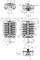
- the rotary cam switch shown in the drawing exists from a switch base 10 with molded on both sides Bearing plates 12, between which a camshaft 14 is rotatable is stored.
- the actuating shaft stands out of the front bearing plate 12 16 before, which are integrally molded with the camshaft or be axially displaceable but rotatably mounted can to actuate further contacts by axial displacement or to sink the switch gag, not shown.
- the front bearing plate 12 carries mounting holes 18 with which the switch on the front panel of a household appliance or the like can be set.
- the camshaft 14 carries eleven switch cam disks according to the illustrated embodiment 20.
- Each switching cam disc 20 acts an actuating plunger 22 on a U-shaped contact bridge 24 a, which is radially displaceably mounted in the base and is supported by a contact pressure spring 26.
- This Contact bridges 24 interact with terminals 28 which inserted into slots 30 of the switch base and, as from Fig. 4 can be seen, fixed by locking or caulking are.
- Each terminal 28 has on its Camshaft 14 side facing a cranked arm 32 on, which carries a contact piece 34, which with a contact piece 36 of the contact bridge 24 cooperates.
- the slots 30 are offset against each other on both sides of the camshaft, and the arms 32 of the terminals 28 are in the opposite Sensed in such a way that their contact pieces 34 each in the plane of the associated contact bridge 24, i.e. to lie in the plane of the assigned cam disk 20 come.
- the camshaft has 11 slots marked 1 to 11 and 1a to 11a arranged, and the spacing of the slots from each other or the distance of the terminals inserted therein 28 is 5 mm, for example.
- the spacing of the slots from each other or the distance of the terminals inserted therein 28 is 5 mm, for example.
- the spacing of the slots from each other or the distance of the terminals inserted therein 28 is 5 mm, for example.
- Fig. 5 shows that facing the operating side of the cam switch Locking device.
- This consists of one on the Camshaft 14 and the actuating shaft 16 arranged rotatably Raststern 40, according to the illustrated embodiment has five locking positions and with a locking roller 42 interacts, which is acted upon by a detent spring 46, which is axially movable in a locking chamber 44.
- Another such locking star 40a is on the opposite Arranged end of the camshaft, and this locking star 40a, can interact with a locking roller and a locking spring, as shown in Fig. 5.
- the stop star points 40a a different number of locking positions, for example seven rest positions. The arrangement can then be made in this way be that the switch is equipped according to Fig.
- the locking positions by the Raster 40 can be determined.
- the same switch can be made according to Fig. 2 are equipped and then with a locking star 40a cooperate, which now determines the rest positions.
- the Locking stars 40 and 40a with different numbers of locking positions are provided on each camshaft. Which one Latching star can take effect by using a locking roller or detent spring is determined in the respective detent chamber become.
- the rear locking star 40a cooperate with the front locking device 42, 46 by turning the camshaft over.
- the control shaft 16 can be inserted into the front or rear of the camshaft become. Or it is molded on both sides, and it the part that is not required is then cut off.
- two each on the camshaft adjacent cam disks different Carry out switching functions with different locking positions.
Abstract
Description
Die Erfindung bezieht sich auf einen Nockendrehschalter, der
im Oberbegriff des Anspruchs 1 angegebenen Gattung. Derartige
Nockendrehschalter werden zum Beispiel in großem Umfang eingesetzt
in Haushaltsgeräten wie Herden, Waschmaschinen, Geschirrspülern,
Wäschetrocknern usw., wo die unterschiedlichsten
Schaltfunktionen durchzuführen sind. Dabei wird, ausgehend von
einer Null-Stellung in der sämtliche Kontakte geöffnet sind,
aufeinanderfolgend in jeder Raststellung ein vorbestimmter
Kontakt geschlossen, oder es werden mehrere vorbestimmte Kontakte
in vorbestimmten Raststellungen geschlossen oder geöffnet,
je nach Anordnung der Nockenscheiben auf der Nockenwelle.The invention relates to a rotary cam switch, the
genus specified in the preamble of
Die unterschiedlichen Schaltfunktionen der verschiedenen Maschinen erfordern eine serienmäßige Anpassung an die jeweils geforderte Kontaktzahl und ihre Funktion, die durch die Nockenwelle bestimmt wird. Zwar ist es möglich, bei einer Serienfertigung für bestimmte Anwendungsfälle einen oder mehrere Kontakte unbelegt zu lassen, jedoch war es im allgemeinen nicht möglich, eine Nockenschalterserie für mehrere Geräte zu benutzen. Zwar war ein Schaltersockel für unterschiedliche Schaltfunktionen anwendbar, aber jede einzelne Schaltfunktion erforderte den Einbau einer individuell angepaßten Nockenwelle. Für jede Schaltfunktion fielen daher bisher mindestens die Werkzeugkosten für die speziell angepaßte Nockenwelle an. Auch bei einer Automatenfertigung der Nockenwelle war die Produktion unterschiedlicher Nockenwellen nachteilig, weil eine häufige Umrüstung erforderlich war.The different switching functions of the different Machines require a standard adaptation to the respective required number of contacts and their function by the camshaft is determined. It is indeed possible for a series production one or more for certain applications Leaving contacts unoccupied, but in general it was not possible to use a cam switch series for several devices. There was a switch base for different ones Switching functions applicable, but every single switching function required the installation of an individually adapted camshaft. For each switching function, therefore, at least so far Tool costs for the specially adapted camshaft. Also the production was at an automatic production of the camshaft different camshafts disadvantageous because of a frequent Retrofitting was required.
Der Erfindung liegt daher die Aufgabe zugrunde, einen gattungsgemäßen Nockendrehschalter so auszubilden, daß er für unterschiedliche Schaltfunktionen bei identisch ausgebildeter Nockenwelle einsetzbar ist. The invention is therefore based on the object, a generic Form rotary cam switch so that it can be used for different Switching functions with an identical camshaft can be used.
Gelöst wird die gestellte Aufgabe durch die im Kennzeichnungsteil
des Anspruchs 1 angegebenen Merkmale. Dadurch daß die Zahl
der auf der Nockenwelle angeordneten Nockenscheiben gegenüber
herkömmlichen Nockenschaltern erhöht wurde, und jede einzelne
Nockenscheibe mit einem zugeordneten Kontakt zusammenwirken
kann, besteht die Möglichkeit, wenigstens zwei unterschiedliche
Schaltfunktionen mit ein und derselben Nockenwelle bei entsprechender
Schalterbestückung durchzuführen. Die Erhöhung der
Nockenscheiben auf einer Nockenwelle könnte natürlich einfach
dadurch bewirkt werden, daß die Nockenwelle verlängert wird.
Der Erfindung liegt jedoch die weitere Aufgabe zugrunde, wenigstens
zwei Schaltfunktionsgruppen in einem Nockenschalter zu
vereinigen, dessen Gesamtbaulänge nicht größer ist, als bei
einem herkömmlichen, für eine einzige Funktion abgestimmten,
Schalter. Eine Lösung dieser Aufgabe setzt voraus, daß der
axiale Abstand der Anschlußklemmen auf dem Schaltersockel verringert
wird und erfindungsgemäß sind tatsächlich die zum
Einstecken der Anschlußklemmen vorgesehenen Schlitze im Schaltersockel
in einem relativ geringen Abstand von z.B. 5 mm angeordnet.
Zweckmäßigerweise wird jedoch nach der Erfindung bei
jeder Bestückung nur jeder zweite Anschlußklemmenschlitz belegt,
so daß sich jeweils der doppelte Abstand von z.B. 10 mm ergibt,
was im Hinblick auf die erforderliche Isolation von Vorteil
ist. Es kann dann die Anordnung so getroffen werden, daß jeweils
jede zweite Schaltnockenscheibe mit einem Schaltkontakt
für eine Serie zusammenwirkt, während die jeweils anderen
Nockenscheiben für eine andere Serie mit entsprechender Bestückung
ausgebildet sind. Es ist jedoch auch möglich, sämtliche
Schlitze mit Anschlußklemmen zu bestücken, so daß alle
Nockenscheiben einer Nockenwelle mit Schaltkontakten zusammenwirken,
wobei dann zweckmäßigerweise der Anschluß über einen
Gruppenstecker hergestellt wird, damit die Steckhülsen gegeneinander
isoliert sind.The task is solved by the in the labeling part
of
Wenn ein erfindungsgemäß ausgebildeter Nockendrehschalter für zwei Serien ausgelegt wird, die eine gleiche Zahl von Raststellungen erfordern, können die Raststellungen durch einen einzigen Raststern auf der Nockenwelle festgelegt werden, der mit entsprechenden Rastkugeln oder Rastrollen zusammenwirkt. Sind unterschiedliche Raststellungen mit unterschiedlichem Winkelabstand erforderlich, können zwei oder mehrere Raststerne auf der Nockenwelle angeordnet werden, von denen jeweils eine Rastvorrichtung mit Rastmitteln im Sockel in Wirkverbindung überführt werden kann. Vorzugsweise wird jeweils ein Raststern an jedem Ende der Nockenwelle angeordnet, die jeweils mit einer Rastvorrichtung des Gehäuses dadurch in Wirkverbindung gebracht werden können, daß Vorderende und Hinterende der Nockenwelle vertauscht in das Gehäuse eingesetzt werden.If a cam rotary switch designed according to the invention for two series is designed, the same number of locking positions require the rest positions by a single locking star to be set on the camshaft interacts with corresponding locking balls or locking rollers. Are different rest positions with different Angular distance required, two or more locking stars be arranged on the camshaft, one of which is Locking device with locking means in the base in operative connection can be transferred. A locking star is preferred in each case arranged at each end of the camshaft, each with a This brings the locking device of the housing into operative connection can be that front end and rear end of the camshaft swapped into the housing.
Bei gleichem Aufbau von Schaltersockel und Schalternockenwelle können wenigstens zwei verschiedene Schalterausführungen gefertigt werden, wobei am Automaten lediglich die Koordinaten für die versetzte Bestückung der Kontakte geändert werden. Wenn die verschiedenen Schalterausführungen auch unterschiedliche Raststellungen, z.B. mit 7 Raststellungen oder 5 Raststellungen erfordern, kann der entsprechende Raststern einmal vorne und einmal hinten an der Nockenwelle vorgesehen werden, und bei der Automatenfertigung können die Rastvorrichtungen des Sockels entsprechend eingebracht werden.With the same structure of switch base and switch camshaft can manufacture at least two different switch designs the coordinates on the machine can be changed for the offset assembly of the contacts. If the different switch versions are also different Rest positions, e.g. with 7 positions or 5 positions may require the corresponding locking star once be provided at the front and once at the rear of the camshaft, and in the manufacture of automatic machines, the locking devices can of the base are inserted accordingly.
Weitere Ausgestaltungen der Erfindung ergeben sich aus den Unteransprüchen.Further refinements of the invention result from the Subclaims.
Nachstehend wird ein Ausführungsbeispiel der Erfindung anhand
der Zeichnung beschrieben. In der Zeichnung zeigen:
Der in der Zeichnung dargestellte Nockendrehschalter besteht
aus einem Schaltersockel 10 mit an beiden Seiten angeformten
Lagerplatten 12, zwischen denen eine Nockenwelle 14 drehbar
gelagert ist. Aus der vorderen Lagerplatte 12 steht die Stellwelle
16 vor, die einstückig mit der Nockenwelle geformt oder
in dieser axial verschieblich, aber drehtest gelagert, sein
kann, um durch axiale Verschiebung weitere Kontakte zu betätigen
oder den nicht dargestellten Schalterknebel zu versanken.
Die vordere Lagerplatte 12 trägt Befestigungslöcher 18, mit
denen der Schalter an der Frontblende eines Haushaltsgerätes
oder dergleichen festgelegt werden kann. Die Nockenwelle 14
trägt gemäß dem dargestellten Ausführungebeispiel elf Schaltnockenscheiben
20. Jede Schaltnockenscheibe 20 wirkt über
einen Betätigungsstößel 22 auf eine U-förmig gestaltete Kontaktbrücke
24 ein, die im Sockel radial verschieblich gelagert
und durch eine Kontaktdruckfeder 26 abgestützt ist. Diese
Kontaktbrücken 24 wirken mit Anschlußklemmen 28 zusammen, die
in Schlitze 30 des Schaltersockels eingesteckt und, wie aus
Fig. 4 ersichtlich, durch Verrastung oder Verstemmung festgelegt
sind. Jede Anschlußklemme 28 weist auf ihrer der
Nockenwelle 14 zugewandten Seite einen abgekröpften Arm 32
auf, der ein Kontaktstück 34 trägt, das mit einem Kontaktstück
36 der Kontaktbrücke 24 zusammenwirkt.The rotary cam switch shown in the drawing exists
from a
Wie aus den Figuren 1 und 2 ersichtlich sind die Schlitze 30
auf den beiden Seiten der Nockenwelle gegeneinander versetzt,
und die Arme 32 der Anschlußklemmen 28 sind im entgegengesetzten
Sinn derart abgekröpft, daß ihre Kontaktstücke 34
jeweils in der Ebene der zugeordneten Kontaktbrücke 24, d.h.
in der Ebene der zugeordneten Nockenscheibe 20, zu liegen
kommen.As can be seen from FIGS. 1 and 2, the
Wie weiter aus den Fig. 1 und 2 ersichtlich, sind beidseitig
der Nockenwelle elf Schlitze mit der Kennzeichnung 1 bis 11
bzw. 1a bis 11a angeordnet, und der Abstand der Schlitze
voneinander bzw. der Abstand der darin eingesteckten Anschlußklemmen
28 beträgt beispielsweise 5 mm. Bei den in der Zeichnung
dargestellten Ausführungsbeispielen nach Fig. 1 und 2
ist nur jeder zweite Schlitz mit einer Anschlußklemme bestückt,
d.h. es verbleibt jeweils zwischen zwei Anschlußklemmen
ein leerer Schlitz. Gemäß Fig. 1 sind sechs Anschlußklemmen
28 in die Schlitze 1, 3, 5, 7, 9, 11 bzw. 1a, 3a, 5a,
7a, 9a und 11a eingesteckt, wodurch sich sechs Schaltkontakte
ergeben, die durch Nockenscheiben betätigt werden, die mit
Nockenscheiben abwechseln, welche keine Funktion ausüben.
Diese letztgenannten Nockenscheiben sind bei der Bestückung
des Schalters gemäß Fig. 2 wirksam, wo die Anschlußklemmen
in die Schlitze 2, 4, 6, 8 und 10 bzw. 2a, 4a, 6a, 8a, 10a
eingesteckt sind. Mit ein und derselben Nockenwelle 14 können
daher unterschiedliche Schaltfunktionen für sechs bzw. fünf
Kontakte durchgeführt werden. Es ist jedoch auch möglich,
alle Schlitze mit Anschlußklemmen zu bestücken, so daß sämtliche
Nockenschaltungen wirksam werden, wobei natürlich auch
für jeden Schaltkontakt eine Brücke eingesetzt werden muß.
Zwischen den Schlitzen 30 bzw. zwischen den Nockenscheiben
20 der Nockenwelle sind im Sockel jeweils L-förmige Stege 38
angeordnet oder eingeformt, die der Isolation und Kontakttrennung
bzw. Lagepositionierung der Anschlußklemmen dienen.As can also be seen from FIGS. 1 and 2, are on both sides
the camshaft has 11 slots marked 1 to 11
and 1a to 11a arranged, and the spacing of the slots
from each other or the distance of the terminals inserted therein
28 is 5 mm, for example. At the in the
Fig. 5 zeigt die der Bedienungsseite des Nockenschalters zugewandte
Rastvorrichtung. Diese besteht aus einem auf der
Nockenwelle 14 bzw. der Stellwelle 16 drehfest angeordneten
Raststern 40, der gemäß dem dargestellten Ausführungsbeispiel
fünf Raststellungen aufweist und mit einer Rastrolle 42
zusammenwirkt, die von einer Rastfeder 46 beaufschlagt ist,
die in einer Rastkammer 44 axial beweglich ist. Ein weiterer
derartiger Raststern 40a ist auf dem gegenüberliegenden
Ende der Nockenwelle angeordnet, und dieser Raststern 40a,
kann mit einer Rastrolle und einer Rastfeder zusammenwirken,
wie dies in Fig. 5 dargestellt ist. Dabei weist der Raststern
40a eine andere Anzahl von Raststellungen, beispielsweise
sieben Raststellungen, auf. Die Anordnung kann dann so getroffen
werden, daß der Schalter mit einer Bestückung gemäß
Fig. 1 zusammenwirkt, wobei die Raststellungen durch den
Rastetern 40 bestimmt werden. Der gleiche Schalter kann gemäß
Fig. 2 bestückt werden und dann mit einem Raststern 40a
zusammenwirken, der nunmehr die Raststellungen bestimmt. Die
Raststerne 40 und 40a mit unterschiedlicher Zahl von Raststellungen
sind auf jeder Nockenwelle vorgesehen. Welcher
Raststern jeweils wirksam wird, kann durch Einsatz von Rastrolle
bzw. Rastfeder in die jeweilige Rastkammer bestimmt
werden. Es ist jedoch auch möglich, den hinteren Raststern
40a mit der vorderen Rastvorrichtung 42, 46 zusammenwirken
zu lassen, indem die Nockenwelle umgedreht wird. Hierdurch
kann eine Rastvorrichtung eingespart werden. Die Stellwelle
16 kann dabei vorn oder hinten in die Nockenwelle eingesetzt
werden. Oder sie wird auf beiden Seiten angeformt, und es
wird dann das jeweils nicht benötigte Teil abgetrennt.Fig. 5 shows that facing the operating side of the cam switch
Locking device. This consists of one on the
Camshaft 14 and the actuating
Bei gleichem Grundaufbau von Schaltersockel und Nockenwelle können daher die unterschiedlichsten Schaltfunktionen durchgeführt werden. Es ist klar, daß bei der Bestückung nicht jeder zweite Schlitz durch Anschlußklemmen belegt sein muß, sondern daß je nach den Forderungen weitere Schaltbrücken wegfallen können, oder es können die dazwischenliegenden Schlitze mit Anschlußklemmen belegt werden, soweit dies die Schaltfunktion der jeweiligen Nockenscheibe bestimmt.With the same basic structure of switch base and camshaft can therefore perform a wide variety of switching functions become. It is clear that the assembly does not every second slot must be occupied by terminals, but that, depending on the requirements, further switching bridges are eliminated can, or the slots in between with terminals, insofar as this is the switching function of the respective cam disc.
Gemäß dem dargestellten Ausführungsbeispiel können jeweils zwei auf der Nockenwelle benachbarte Nockenscheiben unterschiedliche Schaltfunktionen mit unterschiedlichen Raststellungen durchführen. Es ist jedoch auch denkbar und soll für die Erfindung vorbehalten bleiben, mehr als zwei Gruppenfunktionen durchzuführen, indem auf der Nockenwelle mehr als zwei jeweils benachbarte Nockenscheiben vorgesehen sind, die mit zugeordneten Schaltkontakten zusammenwirken. Falls erforderlich können dabei mehr als zwei Raststerne vorgesehen werden. According to the illustrated embodiment, two each on the camshaft adjacent cam disks different Carry out switching functions with different locking positions. However, it is also conceivable and intended for the invention reserved to perform more than two group functions, by placing more than two adjacent ones on the camshaft Cam disks are provided that are associated with Switch contacts interact. If necessary, you can do so more than two locking stars can be provided.
- 1010th
- SchaltersockelSwitch base
- 1212th
- LagerplattenBearing plates
- 1414
- Nockenwellecamshaft
- 1616
- StellwelleControl shaft
- 1818th
- BefestigungslöcherMounting holes
- 2020th
- NockenscheibenCam disks
- 2222
- BetätigungsstößelActuating plunger
- 2424th
- KontaktbrückeContact bridge
- 2626
- KontaktdruckfederContact pressure spring
- 2828
- AnschlußklemmeConnector
- 3030th
- SchlitzeSlits
- 3232
- abgekröpfter Armcranked arm
- 3434
- Kontaktstück (Klemme)Contact piece (clamp)
- 3636
- Kontaktstück (Brücke)Contact piece (bridge)
- 3838
- Stege L-förmig abgekantetL-shaped bridges
- 40,40a40.40a
- RaststernGrid star
- 4242
- RastrolleLocking roller
- 4444
- RastkammerRest area
- 4646
- RastfederDetent spring
Claims (11)
dadurch gekennzeichnet,
daß den Nockenscheiben (20) einer einzigen Nockenwelle (14) wenigstens zwei Gruppen von Schaltkontakten (24) in einem einzigen Schaltersockel (10) zugeordnet werden können.Cam rotary switch, in particular for household appliances, with a camshaft (14) mounted in a switch base (10), with several cam disks (20) provided at an axial distance on the camshaft, with a latching device (40, 42) for fixing the camshaft in several angular positions, and with switching contacts (24) which can be actuated by the cam disks,
characterized,
that the cam disks (20) of a single camshaft (14) can be assigned at least two groups of switching contacts (24) in a single switch base (10).
dadurch gekennzeichnet,
daß zwei Gruppen von Schaltkontakten von jeweils abwechselnden Schaltnockenscheiben (20) der Nockenwelle (14) betätigbar sind.Cam rotary switch according to claim 1,
characterized,
that two groups of switching contacts of alternating switching cam disks (20) of the camshaft (14) can be actuated.
dadurch gekennzeichnet,
daß der Schaltersockel Einsteckschlitze (30) für die Anschlußklemmen bzw. die Schaltkontaktbrücken (24) mit abwechselnder Bestückung für jede Gruppe aufweist.Cam rotary switch according to claims 1 and 2,
characterized,
that the switch base has insertion slots (30) for the connecting terminals or the switching contact bridges (24) with alternating equipment for each group.
dadurch gekennzeichnet,
daß die Nockenwelle (14) wenigstens zwei Raststerne (40,40a) trägt, die mit im Sockel angeordneten Rastvorrichtungen individuell in Wirkverbindung überführbar sind. Cam rotary switch according to one of claims 1 to 3,
characterized,
that the camshaft (14) carries at least two locking stars (40, 40a) which can be individually brought into operative connection with locking devices arranged in the base.
dadurch gekennzeichnet,
daß der axiale Abstand der Anschlußklemmen/Einsteckschlitze (30) im Schaltersockel (10) etwa 5 mm beträgt und der Abstand der in jedem zweiten Schlitz eingesteckten Anschlußklemmen 10 mm beträgt.Cam rotary switch according to one of claims 1 to 4,
characterized,
that the axial distance between the terminals / insertion slots (30) in the switch base (10) is about 5 mm and the distance between the terminals inserted in every second slot is 10 mm.
dadurch gekennzeichnet,
daß die Überbrückungskontakte (24) U-förmig ausgebildet, in einer Sockelausnehmung axial gegen Federdruck (26) verschiebbar sind und über einen angeformten Betätigungsstößel (22) von jeweils einer Nockenscheibe (20) im Sinn einer Kontaktunterbrechung verschiebbar sind.Cam rotary switch according to one of claims 1 to 5,
characterized,
that the bridging contacts (24) are U-shaped, are axially displaceable against spring pressure (26) in a base recess and can be displaced via a molded actuating plunger (22) by a cam (20) in the sense of an interruption of contact.
dadurch gekennzeichnet,
daß die Anschlußklemmen (28) abgekröpfte Arme mit Schaltkontakten (32) aufweisen, die in der Ebene jeweils einer Schaltnockenscheibe liegen.Cam rotary switch according to claims 1 to 6,
characterized,
that the terminals (28) have cranked arms with switch contacts (32) which are each in the plane of a switch cam.
dadurch gekennzeichnet,
daß zwischen den Nockenscheiben bzw. den Anschlußklemmen L-förmig abgekantete Trennstege (38) angeordnet sind.Cam rotary switch according to claims 1 to 7,
characterized,
that separating webs (38) are arranged in an L-shaped manner between the cam disks or the connecting terminals.
dadurch gekennzeichnet,
daß an einem Ende der Nockenwelle (14) ein Raststern (40) für zum Beispiel sieben Raststellungen (für einen Siebentaktschalter) angeordnet und am gegenüberliegenden Ende der Nockenwelle ein Raststern (40a) für beispielsweise fünf Raststellungen (Fünftaktschalter) vorgesehen ist. Cam rotary switch according to claims 1 to 8,
characterized,
that at one end of the camshaft (14) there is a locking star (40) for, for example, seven locking positions (for a seven-stroke switch) and at the opposite end of the camshaft a locking star (40a) for, for example, five locking positions (five-stroke switch) is provided.
dadurch gekennzeichnet,
daß der Schaltersockel im Bereich beider Raststerne (40,40a) eine Rastkammer (44) aufweist, die mit einer Rastfeder (46) und einer Rastrolle (42) wahlweise bestückbar ist.Cam rotary switch according to claim 9,
characterized,
that the switch base in the area of both locking stars (40, 40a) has a locking chamber (44) which can be optionally equipped with a locking spring (46) and a locking roller (42).
dadurch gekennzeichnet,
daß jeder Raststern (40,40a) individuell mit einer Rastvorrichtung des Gehäuses zusammenwirken kann.Cam rotary switch according to claim 9,
characterized,
that each locking star (40, 40a) can interact individually with a locking device of the housing.
Applications Claiming Priority (2)
| Application Number | Priority Date | Filing Date | Title |
|---|---|---|---|
| DE29818196U | 1998-10-12 | ||
| DE29818196U DE29818196U1 (en) | 1998-10-12 | 1998-10-12 | Cam rotary switch |
Publications (1)
| Publication Number | Publication Date |
|---|---|
| EP0994496A1 true EP0994496A1 (en) | 2000-04-19 |
Family
ID=8063801
Family Applications (1)
| Application Number | Title | Priority Date | Filing Date |
|---|---|---|---|
| EP99118415A Withdrawn EP0994496A1 (en) | 1998-10-12 | 1999-09-17 | Rotary cam switch |
Country Status (2)
| Country | Link |
|---|---|
| EP (1) | EP0994496A1 (en) |
| DE (1) | DE29818196U1 (en) |
Cited By (1)
| Publication number | Priority date | Publication date | Assignee | Title |
|---|---|---|---|---|
| CN107104009A (en) * | 2017-06-20 | 2017-08-29 | 王华银 | Multi-path synchronous controls electric brake |
Families Citing this family (1)
| Publication number | Priority date | Publication date | Assignee | Title |
|---|---|---|---|---|
| DE102007013154B4 (en) | 2007-03-20 | 2009-04-02 | Mark Eidloth | Switching device with at least one contact pair |
Citations (3)
| Publication number | Priority date | Publication date | Assignee | Title |
|---|---|---|---|---|
| US3831272A (en) * | 1972-11-13 | 1974-08-27 | Amp Inc | Method of making selective switch contacts |
| DE3618312A1 (en) * | 1986-05-30 | 1987-12-03 | Baer Elektrowerke Gmbh & Co Kg | Switching device |
| EP0860846A2 (en) * | 1997-02-18 | 1998-08-26 | E.G.O. ELEKTRO-GERÄTEBAU GmbH | Electrical power regulator, in particular for electric heaters |
-
1998
- 1998-10-12 DE DE29818196U patent/DE29818196U1/en not_active Expired - Lifetime
-
1999
- 1999-09-17 EP EP99118415A patent/EP0994496A1/en not_active Withdrawn
Patent Citations (3)
| Publication number | Priority date | Publication date | Assignee | Title |
|---|---|---|---|---|
| US3831272A (en) * | 1972-11-13 | 1974-08-27 | Amp Inc | Method of making selective switch contacts |
| DE3618312A1 (en) * | 1986-05-30 | 1987-12-03 | Baer Elektrowerke Gmbh & Co Kg | Switching device |
| EP0860846A2 (en) * | 1997-02-18 | 1998-08-26 | E.G.O. ELEKTRO-GERÄTEBAU GmbH | Electrical power regulator, in particular for electric heaters |
Cited By (2)
| Publication number | Priority date | Publication date | Assignee | Title |
|---|---|---|---|---|
| CN107104009A (en) * | 2017-06-20 | 2017-08-29 | 王华银 | Multi-path synchronous controls electric brake |
| CN107104009B (en) * | 2017-06-20 | 2019-10-08 | 马鞍山久特新材料科技有限公司 | Multi-path synchronous controls electric brake |
Also Published As
| Publication number | Publication date |
|---|---|
| DE29818196U1 (en) | 1999-01-07 |
Similar Documents
| Publication | Publication Date | Title |
|---|---|---|
| EP0609672B1 (en) | Safety switch | |
| DE2020838C3 (en) | Push button switch lock with displacement bodies | |
| EP0019141B1 (en) | Cam switch | |
| DE19726149C2 (en) | Switch arrangement | |
| EP0994496A1 (en) | Rotary cam switch | |
| DE3629921C2 (en) | ||
| EP0542057B1 (en) | Support for the electric motor of a kitchen machine, in particular lemon squeezer | |
| EP0831569B1 (en) | Auxiliary switch | |
| DE202005001495U1 (en) | 2-pole changeover switch | |
| DE3803125C1 (en) | Electrical switch | |
| DE2025982B2 (en) | MULTIPLE CONTACT SYSTEM FOR CAM SWITCHES | |
| DE3232338C2 (en) | Multipole push button switch | |
| DE1142935B (en) | Push button switches, especially for the control of machine tools | |
| DE2416152A1 (en) | CIRCUIT BREAKER | |
| DE2400750C3 (en) | Electrical rotary switch with an insulating plate and two rotors | |
| WO2007012533A1 (en) | Control device for a domestic appliance | |
| DE10032518C1 (en) | Multi-stage electrical switch has switch elements operated in succession by movement of manual operating element via respective switch operating elements | |
| EP1376631B1 (en) | Assembly of at least one switching rocker to the operating rocker of an electrical switch | |
| DE3837653A1 (en) | CONNECTING DEVICE FOR OPERATING BUTTONS | |
| DE2462034C3 (en) | Key suitable for assembling keyboards | |
| DE4204465A1 (en) | Ratcheted system for rotary switch - has different turning resistances within programs or switching steps, used e.g. for washing machine | |
| DE102007056296B4 (en) | Contact device with spring contacts | |
| DE3618312C2 (en) | Switching device | |
| DE2316549B2 (en) | Electric switch | |
| DE2462035A1 (en) | Snap key keyboard structure - has keys snap connected into substructure which has openings in U-shaped formation to accommodate them |
Legal Events
| Date | Code | Title | Description |
|---|---|---|---|
| PUAI | Public reference made under article 153(3) epc to a published international application that has entered the european phase |
Free format text: ORIGINAL CODE: 0009012 |
|
| 17P | Request for examination filed |
Effective date: 20000131 |
|
| AK | Designated contracting states |
Kind code of ref document: A1 Designated state(s): AT BE CH CY DE DK ES FI FR GB GR IE IT LI LU MC NL PT SE |
|
| AX | Request for extension of the european patent |
Free format text: AL;LT;LV;MK;RO PAYMENT 19991006;SI PAYMENT 19991006 |
|
| AKX | Designation fees paid |
Free format text: AT BE CH CY DE DK ES FI FR GB GR IE IT LI LU MC NL PT SE |
|
| AXX | Extension fees paid |
Free format text: RO PAYMENT 19991006;SI PAYMENT 19991006 |
|
| 17Q | First examination report despatched |
Effective date: 20030203 |
|
| STAA | Information on the status of an ep patent application or granted ep patent |
Free format text: STATUS: THE APPLICATION IS DEEMED TO BE WITHDRAWN |
|
| 18D | Application deemed to be withdrawn |
Effective date: 20030814 |