EP0994302A1 - Brûleur à combustible fluide notamment pour fours de réchauffage de produits sidérurgiques - Google Patents
Brûleur à combustible fluide notamment pour fours de réchauffage de produits sidérurgiques Download PDFInfo
- Publication number
- EP0994302A1 EP0994302A1 EP19990402320 EP99402320A EP0994302A1 EP 0994302 A1 EP0994302 A1 EP 0994302A1 EP 19990402320 EP19990402320 EP 19990402320 EP 99402320 A EP99402320 A EP 99402320A EP 0994302 A1 EP0994302 A1 EP 0994302A1
- Authority
- EP
- European Patent Office
- Prior art keywords
- products
- burner
- plane
- tunnel
- burners
- Prior art date
- Legal status (The legal status is an assumption and is not a legal conclusion. Google has not performed a legal analysis and makes no representation as to the accuracy of the status listed.)
- Granted
Links
- 239000000446 fuel Substances 0.000 title claims abstract description 29
- 229910000831 Steel Inorganic materials 0.000 title claims description 6
- 239000010959 steel Substances 0.000 title claims description 6
- 239000007788 liquid Substances 0.000 title 1
- 239000007924 injection Substances 0.000 claims abstract description 34
- 238000002347 injection Methods 0.000 claims abstract description 34
- 238000002485 combustion reaction Methods 0.000 claims abstract description 24
- 238000009826 distribution Methods 0.000 claims abstract description 20
- 239000007800 oxidant agent Substances 0.000 claims abstract description 15
- 230000001590 oxidative effect Effects 0.000 claims abstract description 13
- 230000004907 flux Effects 0.000 claims abstract description 12
- 239000012530 fluid Substances 0.000 claims abstract description 5
- 239000003517 fume Substances 0.000 claims abstract description 4
- 238000010438 heat treatment Methods 0.000 claims description 15
- 230000007480 spreading Effects 0.000 claims description 8
- 238000003303 reheating Methods 0.000 description 7
- 239000000203 mixture Substances 0.000 description 5
- 230000015572 biosynthetic process Effects 0.000 description 2
- 239000007789 gas Substances 0.000 description 2
- 238000002513 implantation Methods 0.000 description 2
- 238000005096 rolling process Methods 0.000 description 2
- 230000005540 biological transmission Effects 0.000 description 1
- 239000000470 constituent Substances 0.000 description 1
- 230000007547 defect Effects 0.000 description 1
- 238000010586 diagram Methods 0.000 description 1
- 239000003344 environmental pollutant Substances 0.000 description 1
- 230000006872 improvement Effects 0.000 description 1
- 238000009434 installation Methods 0.000 description 1
- 238000013021 overheating Methods 0.000 description 1
- 231100000719 pollutant Toxicity 0.000 description 1
- 230000009467 reduction Effects 0.000 description 1
- 239000000126 substance Substances 0.000 description 1
- 238000009827 uniform distribution Methods 0.000 description 1
Images

Classifications
-
- F—MECHANICAL ENGINEERING; LIGHTING; HEATING; WEAPONS; BLASTING
- F27—FURNACES; KILNS; OVENS; RETORTS
- F27D—DETAILS OR ACCESSORIES OF FURNACES, KILNS, OVENS OR RETORTS, IN SO FAR AS THEY ARE OF KINDS OCCURRING IN MORE THAN ONE KIND OF FURNACE
- F27D99/00—Subject matter not provided for in other groups of this subclass
- F27D99/0001—Heating elements or systems
- F27D99/0033—Heating elements or systems using burners
-
- C—CHEMISTRY; METALLURGY
- C21—METALLURGY OF IRON
- C21D—MODIFYING THE PHYSICAL STRUCTURE OF FERROUS METALS; GENERAL DEVICES FOR HEAT TREATMENT OF FERROUS OR NON-FERROUS METALS OR ALLOYS; MAKING METAL MALLEABLE, e.g. BY DECARBURISATION OR TEMPERING
- C21D9/00—Heat treatment, e.g. annealing, hardening, quenching or tempering, adapted for particular articles; Furnaces therefor
- C21D9/0006—Details, accessories not peculiar to any of the following furnaces
-
- F—MECHANICAL ENGINEERING; LIGHTING; HEATING; WEAPONS; BLASTING
- F23—COMBUSTION APPARATUS; COMBUSTION PROCESSES
- F23C—METHODS OR APPARATUS FOR COMBUSTION USING FLUID FUEL OR SOLID FUEL SUSPENDED IN A CARRIER GAS OR AIR
- F23C5/00—Disposition of burners with respect to the combustion chamber or to one another; Mounting of burners in combustion apparatus
- F23C5/08—Disposition of burners
- F23C5/14—Disposition of burners to obtain a single flame of concentrated or substantially planar form, e.g. pencil or sheet flame
-
- F—MECHANICAL ENGINEERING; LIGHTING; HEATING; WEAPONS; BLASTING
- F23—COMBUSTION APPARATUS; COMBUSTION PROCESSES
- F23D—BURNERS
- F23D14/00—Burners for combustion of a gas, e.g. of a gas stored under pressure as a liquid
- F23D14/20—Non-premix gas burners, i.e. in which gaseous fuel is mixed with combustion air on arrival at the combustion zone
- F23D14/22—Non-premix gas burners, i.e. in which gaseous fuel is mixed with combustion air on arrival at the combustion zone with separate air and gas feed ducts, e.g. with ducts running parallel or crossing each other
-
- F—MECHANICAL ENGINEERING; LIGHTING; HEATING; WEAPONS; BLASTING
- F27—FURNACES; KILNS; OVENS; RETORTS
- F27B—FURNACES, KILNS, OVENS OR RETORTS IN GENERAL; OPEN SINTERING OR LIKE APPARATUS
- F27B9/00—Furnaces through which the charge is moved mechanically, e.g. of tunnel type; Similar furnaces in which the charge moves by gravity
- F27B9/30—Details, accessories or equipment specially adapted for furnaces of these types
- F27B9/36—Arrangements of heating devices
-
- C—CHEMISTRY; METALLURGY
- C21—METALLURGY OF IRON
- C21D—MODIFYING THE PHYSICAL STRUCTURE OF FERROUS METALS; GENERAL DEVICES FOR HEAT TREATMENT OF FERROUS OR NON-FERROUS METALS OR ALLOYS; MAKING METAL MALLEABLE, e.g. BY DECARBURISATION OR TEMPERING
- C21D1/00—General methods or devices for heat treatment, e.g. annealing, hardening, quenching or tempering
- C21D1/34—Methods of heating
- C21D1/52—Methods of heating with flames
-
- F—MECHANICAL ENGINEERING; LIGHTING; HEATING; WEAPONS; BLASTING
- F23—COMBUSTION APPARATUS; COMBUSTION PROCESSES
- F23D—BURNERS
- F23D2900/00—Special features of, or arrangements for burners using fluid fuels or solid fuels suspended in a carrier gas
- F23D2900/00012—Liquid or gas fuel burners with flames spread over a flat surface, either premix or non-premix type, e.g. "Flächenbrenner"
- F23D2900/00013—Liquid or gas fuel burners with flames spread over a flat surface, either premix or non-premix type, e.g. "Flächenbrenner" with means for spreading the flame in a fan or fishtail shape over a melting bath
-
- F—MECHANICAL ENGINEERING; LIGHTING; HEATING; WEAPONS; BLASTING
- F27—FURNACES; KILNS; OVENS; RETORTS
- F27B—FURNACES, KILNS, OVENS OR RETORTS IN GENERAL; OPEN SINTERING OR LIKE APPARATUS
- F27B9/00—Furnaces through which the charge is moved mechanically, e.g. of tunnel type; Similar furnaces in which the charge moves by gravity
- F27B9/14—Furnaces through which the charge is moved mechanically, e.g. of tunnel type; Similar furnaces in which the charge moves by gravity characterised by the path of the charge during treatment; characterised by the means by which the charge is moved during treatment
- F27B9/20—Furnaces through which the charge is moved mechanically, e.g. of tunnel type; Similar furnaces in which the charge moves by gravity characterised by the path of the charge during treatment; characterised by the means by which the charge is moved during treatment the charge moving in a substantially straight path
- F27B9/201—Furnaces through which the charge is moved mechanically, e.g. of tunnel type; Similar furnaces in which the charge moves by gravity characterised by the path of the charge during treatment; characterised by the means by which the charge is moved during treatment the charge moving in a substantially straight path walking beam furnace
- F27B9/202—Conveyor mechanisms therefor
- F27B9/203—Conveyor mechanisms therefor having ramps
Definitions
- the present invention relates to a fluid fuel burner in particular for furnaces for heating steel products.
- the object of this invention is design of a spread flame burner which improves the distribution of heat fluxes generated by said flame, in order to reduce the heterogeneity of temperature induced in the products to be heated.
- heat treatment furnaces in particular reheating, hold are intended to carry products, including slabs, blooms and similar, at temperatures required for example for rolling or for obtaining a given metallurgical structure.
- the level of average temperature is obtained by passing the products through so-called zones which are characterized by a significant thermal input in a relatively short time, which generates great thermal heterogeneity in reheated products.
- the products leaving the heating zones pass through an equalization zone in which the heat input is very low, which provides equalization of temperatures within products.
- the products to be heated are supported and transported inside the oven by a system of rails fixed 2 and mobile 3, the mobile beams 3 being moved by actions combined with a travel chassis 4 and a lifting chassis 5 giving the products 1 a movement with the conveyor's steps so as to lead them from the entrance to the oven outlet.
- This is a system well known to those skilled in the art, which does not is not part of the present invention and therefore need not be described in detail.
- the oven consists of a heat-insulated enclosure 6, comprising respectively heating zones and equalization zones and on which are arranged upper 7 and lower 7 'heating burners as well as burners equalization 8 installed in the oven roof as can be clearly seen on the Figure 1.
- the burners of the heating zones 7 and 7 ' which are located on the side walls of the oven are flame burners axisymmetric, axial development.
- the products to be treated are placed in a horizontal plane parallel to the axes of the burners. These can be implemented either in a plane situated above the plane of the product bed (upper burners 7), either in a plane located below the plane of the product bed (lower burners 7 ').
- the height of the oven enclosure 6 is defined by the distance between the plane of the products 1 of the oven floor and by the distance separating the plane of said products from the vault of the oven. This height is determined according to the characteristics and flame dimensions of burners 7 and 7 'located in the side walls of the oven.
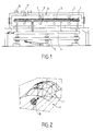
- FIG. 2 of the accompanying drawings there is shown schematically, the distribution of the heat flux produced by the burners 7, 7 'with axisymmetric flames with axial development.
- the reference B designates a burner
- P the plane of the product bed
- I the image of the heat flows transmitted.
- the flow thermal has heterogeneities in the perpendicular vertical planes and parallel to the axis of the flame. These heterogeneities are caused by the gradual development of combustion at the root of the flame or by the presence of hot zones in this flame, characteristics of this type of known burner.
- the oven also includes burners 8 located on the roof of the oven in the equalization areas of the latter. It is flame burners with low axial impulse and high flame rotation (Important "swirl").
- the heat flux transmitted to the products to be heated is constant over a certain diameter, in a plane perpendicular to the axis of the burner 8 and parallel to the bed of products 1.
- These burners generate heterogeneities thermal limits in these products, however the radiative exchange surface homogeneous created by each burner is limited to a small unit area, which requires the installation of a large number of burners such as 8 to ensure uniform heating of the entire surface of the products.
- the location of the burners 8 in the roof of the oven In this figure, the reference Z designates the main heating zone of each burner 8 on the roof of the furnace, Pv designates the plane of the roof of the furnace and Ip designates the image of the flows thermal transmissions on the product bed plan.
- the lower burners 7 ′ which are located under the plane of the products 1 do not can be replaced by burners with low axial impulse and high setting flame rotation because their implantation in the oven bottom is impossible in due to the presence of equipment for supporting products and falls of part of the oxides that form during reheating on the surface of these products.
- Lower burners such as 7 'equalization zones cannot so be that axisymmetric flame burners, with axial development, despite the thermal flow distribution defects inherent in this type of burner.
- the present invention proposes to provide a burner limiting the heterogeneities of distribution of heat flow in planes vertical parallel and perpendicular to the flame axis, spreading the surface of exchange between the flame and the plane of the bed of the products to be treated.
- figure 4 represents the distribution of the heat flow of the flame of a burner produced in accordance with the provisions of the present invention.
- the reference B designates the burner
- the reference P designates the floor plan of the products
- the reference I the image of the heat flows transmitted.
- This Figure 4 clearly shows that the burner according to the invention develops a flame spread parallel to the bed of products and whose flow is preferentially in the plane of the major axis of symmetry of the tunnel, parallel to the plane of the products.
- a comparison between this figure 4 and figure 2 commented above makes it clear appear the technical progress provided by the invention vis-à-vis the burners according to the prior art.
- a burner according to the present invention which is essentially characterized in that it is provided with a combustion tunnel having an enlarged shape, provided with oxidant injection ports and fuel, substantially parallel to the major axis of symmetry of said tunnel, the shape inside of the latter as well as the orientation of the fuel injection orifices and by oxidizing being chosen so as to create a difference in the distribution of products of combustion and recycled fumes, producing a spread flame ensuring a uniform distribution of the heat flow.
- said combustion tunnel has a shape rectangular, oval, or any combination of these two shapes.
- the axes of the injection orifices of the oxidizer and / or fuel are located in planes substantially parallel to the plan of the products to be treated.
- the injection channels open into the tunnel through the orifices of fuel injection or, in the case where the invention is applied to burners with separate fuel injection pipes, fuel injection channels and ports fuel are located in the injection pipe.
- the burner includes modulation means of the surface on which the burner flame is distributed, these means being able be made by delivering the oxidant and / or fuel in at least two groups separated.
- the invention also relates to an oven provided with burners having the characteristics defined above, in particular an oven for heating steel products.
- This oven may have a radiant wall or exchange wall, arranged substantially parallel to the plan of the products to be treated, opposite the plan of spreading of burner flames. These burners are arranged so that the spreading plane flame is substantially parallel to one of the walls of the furnace.
- the burners can be installed on the side walls of the oven, on one at less of these front walls, above and / or below the plane of the products to treat.
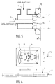
- FIGS 5 and 6 illustrate a first embodiment of a burner according to the present invention.
- this burner has a tunnel of combustion 10, of enlarged shape, rectangular in the exemplary embodiment not limiting illustrated by these figures, of dimensions L and H and whose major axis of symmetry included in the plane PS is arranged substantially parallel to the plane P of products 1 to be treated.
- the combustion tunnel 10 can be produced in any other enlarged form, such as for example oval or any combination of an oval and a rectangular shape with an L / H ratio greater than 1.
- the walls of the combustion tunnel 10 can be flared to the depth F as illustrated in figure 5.
- the supply of fuel is connected to the burner at 12, this fuel being injected via orifices 14.
- the supply of oxidant, air in this embodiment nonlimiting is connected to the burner at 11, the combustion injection being carried out by through holes 13.
- the fuel injection and oxidizer channels are distributed around the axis of the burner. Their axes are arranged in planes substantially parallel to the plane PS in order to ensure a privileged distribution of each fluid which causes spreading the flame in a plane substantially parallel to the PS and P planes.
- the burner thus produces at the exit of the tunnel 10, a spread flame with a homogeneous distribution of heat flow in a plane substantially parallel to the plane PS.
- the distribution of the heat flux obtained is consistent with the representation of the figure 4.
- the burner can be provided devices for modulating the surface on which the heat flux is distributed of the flame of this burner.
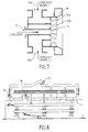
- An exemplary embodiment of such a device is illustrated. by figure 7.
- the oxidizer is delivered in two separate groups 11A and 11B respectively supplying two groups of channels injection lines 13A and 13B, the axes of the injection channels 13A and 13B are substantially parallel to the PS plane.
- the two groups of channels can be inclined to the axis of the burner, identical or different.
- Modulation of the ratio of flow rates and pressures of the two oxidant flows passing through the two groups of injection channels 13A and 13B makes it possible to modulate the surface on which the flame spreads.
- the same arrangement can be adopted with regard to the fuel supply, which may be also carried out in separate groups to control and modulate the surface on which the thermal flow of the burner is distributed.
- the burner object of the present invention and described above can equip in particular an oven for reheating steel products, a holding oven or a heat treatment oven, it being understood that these application examples have not no limiting character.
- the burners are arranged in these ovens so that the flame spreading plan is substantially parallel to one of the walls of the oven in order to obtain a radiant wall substantially parallel to the plane of the products treat.
- the burners which are the subject of the present invention can be installed on the walls sides of an oven as shown in Figure 1, above and below of the plan P of the products as illustrated in 7 and 7 'in this figure 1, in order to heat up said products homogeneously on their upper and lower faces.
- the burners according to the invention can also be arranged on at least one front walls of the oven, above and / or below the plane P of the products to treat.
- FIG. 8 illustrates several known examples of frontal implantation of burners in a reheating oven of the type according to figure 1.
- the burners 15 can be installed on the end walls of the oven, above or below of the plane P of the products, the burners 16 can be installed at any point of the length of the oven, below the plane P of the products and the burners 17 can be located at all points along the length of the oven, above the plane P of the products.
- the burner object of the present invention can be implanted in plans located either above or below the products as seen above with reference to Figure 1.
Landscapes
- Engineering & Computer Science (AREA)
- Chemical & Material Sciences (AREA)
- Mechanical Engineering (AREA)
- General Engineering & Computer Science (AREA)
- Combustion & Propulsion (AREA)
- Materials Engineering (AREA)
- Thermal Sciences (AREA)
- Crystallography & Structural Chemistry (AREA)
- Physics & Mathematics (AREA)
- Metallurgy (AREA)
- Organic Chemistry (AREA)
- Furnace Details (AREA)
- Nozzles For Spraying Of Liquid Fuel (AREA)
- Physical Or Chemical Processes And Apparatus (AREA)
- Tunnel Furnaces (AREA)
- Pre-Mixing And Non-Premixing Gas Burner (AREA)
Abstract
Description
- d'une part, une alimentation en comburant munie de canaux d'injection débouchant dans le tunnel de combustion par l'intermédiaire desdits orifices d'injection, ces derniers étant répartis autour de l'axe du brûleur et ayant des axes qui sont situés dans des plans sensiblement parallèles au plan des produits à traiter et,
- d'autre part, une alimentation en carburant disposée centralement et munie de canaux d'injection qui sont répartis autour de l'axe du brûleur, leurs axes étant situés dans des plans sensiblement parallèles au plan des produits.
- La figure 1, qui a été discutée ci-dessus, représente en élévation latérale et coupe verticale, un exemple de réalisation d'un four auquel peut s'appliquer la présente invention ;
- La figure 2 illustre la répartition du flux thermique produit par des brûleurs actuellement connus, du type discuté ci-dessus ;
- La figure 3, discutée ci-dessus, est un schéma illustrant la répartition des brûleurs de voûte prévus dans les zones d'égalisation du four connu illustré par la figure 1 ;
- La figure 4 représente la répartition du flux thermique de la flamme d'un brûleur selon la présente invention ,
- La figure 5 est une vue schématique du brûleur selon un premier exemple de réalisation de l'invention, en coupe par un plan parallèle aux plans P et PS de la figure 6 ;
- La figure 6 est une vue de ce même brûleur, depuis l'intérieur du four et,
- La figure 7 est une vue similaire à la figure 5 illustrant un second exemple de réalisation du brûleur, objet de la présente invention.
- de réduire la durée de la phase d'égalisation des températures des produits, donc la longueur de la zone des fours de réchauffage dans laquelle cette égalisation de température est opérée.
- de limiter les risques de surchauffe localisée du produit grâce à l'absence de zone chaude ou de point chaud dans la flamme. Cette caractéristique permet l'amélioration de l'état métallurgique final du produit traité.
- de répartir la combustion sur une surface plus importante, ce qui permet de mieux contrôler le mélange de ces fluides donc la composition de l'atmosphère du four et des fumées. Ceci réduit les émissions de polluants générés par la combustion et réduit la formation d'oxydes à la surface des produits réchauffés.
- de réduire la hauteur du laboratoire du four grâce à la réduction de la dimension de la flamme perpendiculairement au plan des produits ou à la réduction du nombre de brûleurs.
- de remplacer un nombre important de brûleurs implantés sur la voûte du four par un nombre plus réduit de brûleurs implantés sur les parois du four. Le circuit de distribution de carburant et de comburant est plus réduit et il est réalisé pour un coût plus faible.
Claims (18)
- Brûleur à combustible fluide du type à flamme axisymétrique à développement axial caractérisé en ce qu'il est muni d'un tunnel de combustion (10), présentant une forme élargie, munie d'orifices d'injection de comburant (13) et de carburant (14) sensiblement parallèles au grand axe de symétrie dudit tunnel, la forme intérieure de ce dernier ainsi que l'orientation des orifices d'injection en carburant (14) et en comburant (13) étant choisies de manière à créer une différence de répartition des produits de combustion et des fumées recyclées, produisant une flamme étalée assurant une répartition homogène du flux thermique.
- Brûleur selon la revendication 1 caractérisé en ce qu'il est muni d'un tunnel de combustion (10) de forme rectangulaire.
- Brûleur selon la revendication 1 caractérisé en ce qu'il est muni d'un tunnel de combustion (10) de forme ovale.
- Brûleur selon la revendication 1 caractérisé en ce que la forme du tunnel de combustion (10) est une combinaison quelconque des formes rectangulaire et ovale.
- Brûleur selon l'une quelconque des revendications précédentes caractérisé en ce que les axes des orifices d'injection de comburant (13) et/ou de carburant (14) sont situés dans des plans sensiblement parallèles au plan (P) des produits à traiter (1).
- Brûleur selon l'une quelconque des revendications précédentes caractérisé en ce qu'il comporte une alimentation en comburant (11) munie de canaux d'injection débouchant dans ledit tunnel par lesdits orifices d'injection (13), ces derniers étant répartis autour de l'axe du brûleur et ayant des axes qui sont situés dans des plans sensiblement parallèles au plan P des produits.
- Brûleur selon l'une quelconque des revendications précédentes caractérisé en ce qu'il comporte une alimentation en carburant (12) disposée centralement et munie de canaux d'injection qui sont répartis autour de l'axe du brûleur, leurs axes étant situés dans des plans sensiblement parallèles au plan (P) des produits à traiter.
- Brûleur selon l'une quelconque des revendications précédentes caractérisé en ce que les canaux d'injection en carburant débouchent dans le tunnel de combustion (10) par lesdits orifices d'injection (14) .
- Brûleur selon l'une quelconque des revendications 1 à 7 caractérisé en ce qu'il est du type à canne d'injection de carburant séparée, les canaux et les orifices d'injection de carburant étant situés dans la canne d'injection.
- Brûleur selon l'une quelconque des revendications précédentes caractérisé en ce que le comburant et/ou le carburant sont délivrés en au moins deux groupes séparés.
- Brûleur selon la revendication 10 caractérisé en ce que le comburant est délivré en deux groupes séparés (11A, 11B) alimentant respectivement deux groupes de canaux d'injection (13A, 13B), les axes desdits canaux d'injection étant sensiblement parallèles au plan (P) des produits.
- Brûleur selon la revendication 11 caractérisé en ce que les deux groupes de canaux d'injection sont inclinés par rapport à l'axe du brûleur, de façon identique ou différente.
- Brûleur selon l'une quelconque des revendications précédentes caractérisé en ce que les parois du tunnel de combustion (10) sont évasées sur sa profondeur (F).
- Four notamment de réchauffage de produits sidérurgiques caractérisé en ce qu'il est équipé de brûleurs selon l'une quelconque des revendications précédentes.
- Four selon la revendication 14 caractérisé en ce qu'il comporte une paroi radiante ou paroi d'échange, disposée sensiblement parallèlement au plan (PS) des produits à traiter, en regard du plan d'étalement des flammes desdits brûleurs.
- Four selon l'une des revendications 14 ou 15 caractérisé en ce que lesdits brûleurs sont disposés de manière que le plan d'étalement de la flamme soit sensiblement parallèle à l'une des parois du four.
- Four selon l'une quelconque des revendications 14 à 16 caractérisé en ce que les brûleurs sont implantés sur ses parois latérales, au dessus et/ou en dessous du plan (P) des produits à traiter.
- Four selon l'une quelconque des revendications 14 à 17 caractérisé en ce qu'il comporte également des brûleurs disposés sur l'une au moins de ses parois frontales, au dessus et/ou en dessous du plan (P) des produits à traiter.
Applications Claiming Priority (2)
| Application Number | Priority Date | Filing Date | Title |
|---|---|---|---|
| FR9812824A FR2784449B1 (fr) | 1998-10-13 | 1998-10-13 | Bruleur a combustible fluide notamment pour fours de rechauffage de produits siderurgiques |
| FR9812824 | 1998-10-13 |
Publications (2)
| Publication Number | Publication Date |
|---|---|
| EP0994302A1 true EP0994302A1 (fr) | 2000-04-19 |
| EP0994302B1 EP0994302B1 (fr) | 2004-01-14 |
Family
ID=9531505
Family Applications (1)
| Application Number | Title | Priority Date | Filing Date |
|---|---|---|---|
| EP19990402320 Expired - Lifetime EP0994302B1 (fr) | 1998-10-13 | 1999-09-22 | Brûleur à combustible fluide notamment pour fours de réchauffage de produits sidérurgiques |
Country Status (9)
| Country | Link |
|---|---|
| US (1) | US6334770B1 (fr) |
| EP (1) | EP0994302B1 (fr) |
| JP (1) | JP2000121011A (fr) |
| CN (1) | CN1111203C (fr) |
| AT (1) | ATE257929T1 (fr) |
| CA (1) | CA2286407C (fr) |
| DE (1) | DE69914153T2 (fr) |
| ES (1) | ES2211008T3 (fr) |
| FR (1) | FR2784449B1 (fr) |
Cited By (2)
| Publication number | Priority date | Publication date | Assignee | Title |
|---|---|---|---|---|
| FR2927409A1 (fr) * | 2008-02-11 | 2009-08-14 | Air Liquide | Procede de chauffage d'un cru mineral dans un four de cuisson de type four tunnel |
| US10260743B2 (en) | 2013-11-26 | 2019-04-16 | Fives Stein | Burner for a reheating furnace or heat treatment furnace for steel industry |
Families Citing this family (15)
| Publication number | Priority date | Publication date | Assignee | Title |
|---|---|---|---|---|
| US20030170579A1 (en) * | 2002-03-07 | 2003-09-11 | Shoou-I Wang | Burner assembly for delivery of specified heat flux profiles in two dimensions |
| US6912756B2 (en) * | 2002-11-13 | 2005-07-05 | American Air Liquide, Inc. | Lance for injecting fluids for uniform diffusion within a volume |
| FR2853959B1 (fr) * | 2003-04-18 | 2005-06-24 | Stein Heurtey | Procede de controle de l'homogeneite de temperature des produits dans un four de rechauffage de siderurgie, et four de rechauffage |
| US20070037106A1 (en) * | 2005-08-12 | 2007-02-15 | Kobayashi William T | Method and apparatus to promote non-stationary flame |
| US20080006225A1 (en) * | 2006-07-06 | 2008-01-10 | William Thoru Kobayashi | Controlling jet momentum in process streams |
| SE534717C2 (sv) * | 2010-05-04 | 2011-11-29 | Linde Ag | Förfarande för att öka värmehomogeniteten i en gropugn |
| SE534084C2 (sv) * | 2010-05-04 | 2011-04-26 | Linde Ag | Förfarande för att öka värmehomogeniteten i en gropugn |
| SE535197C2 (sv) * | 2010-09-30 | 2012-05-15 | Linde Ag | Förfarande vid förbränning i en industriugn |
| US8915731B2 (en) | 2010-12-30 | 2014-12-23 | L'air Liquide Societe Anonyme Pour L'etude Et L'exploitation Des Procedes Georges Claude | Flameless combustion burner |
| US9677760B2 (en) * | 2011-01-28 | 2017-06-13 | Osaka Gas Co., Ltd. | Furnace heating combustion apparatus |
| CN103727539A (zh) * | 2012-10-11 | 2014-04-16 | 丹阳市江南工业炉有限公司 | 加热炉的平焰喷嘴 |
| JP6408135B2 (ja) | 2015-03-31 | 2018-10-17 | 三菱日立パワーシステムズ株式会社 | 燃焼バーナ及びこれを備えたボイラ |
| JP6408134B2 (ja) * | 2015-03-31 | 2018-10-17 | 三菱日立パワーシステムズ株式会社 | 燃焼バーナ及びボイラ |
| JP6642912B2 (ja) | 2015-09-11 | 2020-02-12 | 三菱日立パワーシステムズ株式会社 | 燃焼バーナ及びこれを備えたボイラ |
| JP6691428B2 (ja) * | 2016-05-11 | 2020-04-28 | 東京瓦斯株式会社 | バーナ |
Citations (7)
| Publication number | Priority date | Publication date | Assignee | Title |
|---|---|---|---|---|
| US3676048A (en) * | 1970-03-13 | 1972-07-11 | Pyronics Inc | Excess air burner |
| GB2117506A (en) * | 1982-03-25 | 1983-10-12 | Nu Way Energy Ltd | Burner for gaseous fuels |
| WO1990002907A1 (fr) * | 1988-09-02 | 1990-03-22 | American Combustion, Inc. | Procede et appareil pour produire une flamme extremement lumineuse |
| US4927357A (en) * | 1988-04-01 | 1990-05-22 | The Boc Group, Inc. | Method for gas lancing |
| EP0710798A2 (fr) * | 1994-11-04 | 1996-05-08 | Air Products And Chemicals, Inc. | Brûleur oxy-combustible |
| EP0762050A2 (fr) * | 1995-09-05 | 1997-03-12 | Air Products And Chemicals, Inc. | Brûleur à combustion étagée à faible émission de NOx pour le chauffage contrÔlé par rayonnement des fours à haute température |
| US5725367A (en) * | 1994-12-30 | 1998-03-10 | Combustion Tec, Inc. | Method and apparatus for dispersing fuel and oxidant from a burner |
Family Cites Families (12)
| Publication number | Priority date | Publication date | Assignee | Title |
|---|---|---|---|---|
| US3854918A (en) * | 1972-03-27 | 1974-12-17 | Anchor Hocking Corp | Method for continuous heat treating of glass articles |
| JPS57192215A (en) * | 1981-05-21 | 1982-11-26 | Ishikawajima Harima Heavy Ind Co Ltd | Metal-heating oven |
| US4397451A (en) * | 1981-06-10 | 1983-08-09 | Chugai Ro Kogyo Co., Ltd. | Furnace for the heat treatment of scale-covered steel |
| US4443182A (en) * | 1981-11-10 | 1984-04-17 | Hauck Manufacturing Company | Burner and method |
| US4523530A (en) * | 1982-02-26 | 1985-06-18 | Sumitomo Metal Industries, Ltd. | Powdery coal burner |
| US4717334A (en) * | 1982-11-24 | 1988-01-05 | Gte Products Corporation | Ceramic burner having high turndown ratio |
| JP2638394B2 (ja) * | 1992-06-05 | 1997-08-06 | 日本ファーネス工業株式会社 | 低NOx燃焼法 |
| US5554022A (en) * | 1994-10-14 | 1996-09-10 | Xothermic, Inc. | Burner apparatus and method |
| US5545031A (en) * | 1994-12-30 | 1996-08-13 | Combustion Tec, Inc. | Method and apparatus for injecting fuel and oxidant into a combustion burner |
| GB2300102B (en) * | 1995-03-28 | 1998-07-08 | United Biscuits Ltd | Improvements in and relating to ovens |
| US5743723A (en) * | 1995-09-15 | 1998-04-28 | American Air Liquide, Inc. | Oxy-fuel burner having coaxial fuel and oxidant outlets |
| US5906485A (en) * | 1998-02-27 | 1999-05-25 | Reading Pretzel Machinery Corporation | Tunnel-type conveyor oven having two types of heat sources |
-
1998
- 1998-10-13 FR FR9812824A patent/FR2784449B1/fr not_active Expired - Fee Related
-
1999
- 1999-09-22 DE DE1999614153 patent/DE69914153T2/de not_active Expired - Lifetime
- 1999-09-22 AT AT99402320T patent/ATE257929T1/de active
- 1999-09-22 EP EP19990402320 patent/EP0994302B1/fr not_active Expired - Lifetime
- 1999-09-22 ES ES99402320T patent/ES2211008T3/es not_active Expired - Lifetime
- 1999-10-07 CA CA 2286407 patent/CA2286407C/fr not_active Expired - Fee Related
- 1999-10-07 US US09/414,068 patent/US6334770B1/en not_active Expired - Lifetime
- 1999-10-13 JP JP29098399A patent/JP2000121011A/ja active Pending
- 1999-10-13 CN CN99121511A patent/CN1111203C/zh not_active Expired - Fee Related
Patent Citations (7)
| Publication number | Priority date | Publication date | Assignee | Title |
|---|---|---|---|---|
| US3676048A (en) * | 1970-03-13 | 1972-07-11 | Pyronics Inc | Excess air burner |
| GB2117506A (en) * | 1982-03-25 | 1983-10-12 | Nu Way Energy Ltd | Burner for gaseous fuels |
| US4927357A (en) * | 1988-04-01 | 1990-05-22 | The Boc Group, Inc. | Method for gas lancing |
| WO1990002907A1 (fr) * | 1988-09-02 | 1990-03-22 | American Combustion, Inc. | Procede et appareil pour produire une flamme extremement lumineuse |
| EP0710798A2 (fr) * | 1994-11-04 | 1996-05-08 | Air Products And Chemicals, Inc. | Brûleur oxy-combustible |
| US5725367A (en) * | 1994-12-30 | 1998-03-10 | Combustion Tec, Inc. | Method and apparatus for dispersing fuel and oxidant from a burner |
| EP0762050A2 (fr) * | 1995-09-05 | 1997-03-12 | Air Products And Chemicals, Inc. | Brûleur à combustion étagée à faible émission de NOx pour le chauffage contrÔlé par rayonnement des fours à haute température |
Cited By (4)
| Publication number | Priority date | Publication date | Assignee | Title |
|---|---|---|---|---|
| FR2927409A1 (fr) * | 2008-02-11 | 2009-08-14 | Air Liquide | Procede de chauffage d'un cru mineral dans un four de cuisson de type four tunnel |
| WO2009101361A3 (fr) * | 2008-02-11 | 2009-10-08 | L'air Liquide Societe Anonyme Pour L'etude Et L'exploitation Des Procedes Georges Claude | Procede de chauffage d'un cru mineral dans un four de cuisson de type four tunnel |
| US10260743B2 (en) | 2013-11-26 | 2019-04-16 | Fives Stein | Burner for a reheating furnace or heat treatment furnace for steel industry |
| EP3074695B1 (fr) * | 2013-11-26 | 2020-01-01 | Fives Stein | Brûleur pour un four de réchauffage de produits sidérurgiques ou pour un four de traitement thermique |
Also Published As
| Publication number | Publication date |
|---|---|
| DE69914153D1 (de) | 2004-02-19 |
| JP2000121011A (ja) | 2000-04-28 |
| EP0994302B1 (fr) | 2004-01-14 |
| ATE257929T1 (de) | 2004-01-15 |
| DE69914153T2 (de) | 2004-06-24 |
| CN1250814A (zh) | 2000-04-19 |
| FR2784449B1 (fr) | 2000-12-29 |
| ES2211008T3 (es) | 2004-07-01 |
| US6334770B1 (en) | 2002-01-01 |
| CN1111203C (zh) | 2003-06-11 |
| FR2784449A1 (fr) | 2000-04-14 |
| CA2286407A1 (fr) | 2000-04-13 |
| CA2286407C (fr) | 2008-08-26 |
Similar Documents
| Publication | Publication Date | Title |
|---|---|---|
| EP0994302B1 (fr) | Brûleur à combustible fluide notamment pour fours de réchauffage de produits sidérurgiques | |
| EP0850200B1 (fr) | PROCEDE ET DISPOSITIF POUR LA REDUCTION DE L'EMISSION DE NOx DANS UN FOUR DE VERRERIE | |
| EP2148935B1 (fr) | Procede et installation de chauffage d'une bande metallique, notamment en vue d'un recuit | |
| EP0167447B1 (fr) | Procédé de chauffage d'un canal contenant du verre à l'aide de flammes oxycombustibles | |
| EP0481835B1 (fr) | Procédé de chauffe d'une enceinte thermique et brûleur | |
| EP1031790A1 (fr) | Perfectionnements apportés aux brûleurs à flamme plate | |
| EP0242249B1 (fr) | Brûleur à faible émission de gaz polluants | |
| FR3033025A1 (fr) | Alambic equipe d'un tour a feu a deux etages | |
| EP1702177A1 (fr) | Procede de combustion etagee avec injection optimisee de l'oxydant primaire | |
| EP1001237A1 (fr) | Procédé de chauffage d'un four à chargement continu notamment pour produits sidérurgiques, et four de chauffage à chargement continu | |
| EP0850883A2 (fr) | Procédé de fabrication de verre technique et brûleur pour la mise en oeuvre d'un tel procédé | |
| FR2486643A1 (fr) | Four pour la cuisson de pieces ceramiques | |
| EP3671038B1 (fr) | Ensemble et procédé pour l'injection d'un agent de combustion gazeux | |
| FR2488277A1 (fr) | Four pour le chauffage de metal et en particulier de profiles intermediaires avant leur laminage | |
| FR3013803A1 (fr) | Bruleur de four de rechauffement de produits siderurgiques ou de four de traitement thermique | |
| FR2948929A1 (fr) | Four de fusion de matieres premieres vitrifiables avec zone de prechauffage optimisee | |
| FR2926350A1 (fr) | Procede et four de fusion. | |
| FR3114375A1 (fr) | Bruleur, notamment pour section de prechauffage a flamme directe de ligne continue de traitement d’une bande metallique | |
| FR2670801A1 (fr) | Dispositif d'allumage d'un lit de melange de materiaux tels que du minerai et du coke. | |
| EP0211699A1 (fr) | Brûleur avec des caloducs pour le préchauffage de l'air et du combustible | |
| FR2678356A1 (fr) | Bruleur catalytique a air induit. | |
| FR2947037A1 (fr) | Appareil de chauffage avec conduit d'introduction d'air | |
| BE517267A (fr) | ||
| CA3192833A1 (fr) | Section de prechauffage a flamme directe pour ligne continue de traitement de bandes metalliques | |
| FR2745063A1 (fr) | Bruleur radiant pour la combustion a l'oxygene |
Legal Events
| Date | Code | Title | Description |
|---|---|---|---|
| PUAI | Public reference made under article 153(3) epc to a published international application that has entered the european phase |
Free format text: ORIGINAL CODE: 0009012 |
|
| AK | Designated contracting states |
Kind code of ref document: A1 Designated state(s): AT BE CH CY DE DK ES FI FR GB GR IE IT LI LU MC NL PT SE |
|
| AX | Request for extension of the european patent |
Free format text: AL;LT;LV;MK;RO;SI |
|
| 17P | Request for examination filed |
Effective date: 20000906 |
|
| AKX | Designation fees paid |
Free format text: AT BE CH CY DE DK ES FI FR GB GR IE IT LI LU MC NL PT SE |
|
| 17Q | First examination report despatched |
Effective date: 20030324 |
|
| GRAP | Despatch of communication of intention to grant a patent |
Free format text: ORIGINAL CODE: EPIDOSNIGR1 |
|
| GRAS | Grant fee paid |
Free format text: ORIGINAL CODE: EPIDOSNIGR3 |
|
| GRAA | (expected) grant |
Free format text: ORIGINAL CODE: 0009210 |
|
| AK | Designated contracting states |
Kind code of ref document: B1 Designated state(s): AT BE CH CY DE DK ES FI FR GB GR IE IT LI LU MC NL PT SE |
|
| PG25 | Lapsed in a contracting state [announced via postgrant information from national office to epo] |
Ref country code: IE Free format text: LAPSE BECAUSE OF FAILURE TO SUBMIT A TRANSLATION OF THE DESCRIPTION OR TO PAY THE FEE WITHIN THE PRESCRIBED TIME-LIMIT Effective date: 20040114 Ref country code: FI Free format text: LAPSE BECAUSE OF FAILURE TO SUBMIT A TRANSLATION OF THE DESCRIPTION OR TO PAY THE FEE WITHIN THE PRESCRIBED TIME-LIMIT Effective date: 20040114 Ref country code: CY Free format text: LAPSE BECAUSE OF FAILURE TO SUBMIT A TRANSLATION OF THE DESCRIPTION OR TO PAY THE FEE WITHIN THE PRESCRIBED TIME-LIMIT Effective date: 20040114 |
|
| REG | Reference to a national code |
Ref country code: GB Ref legal event code: FG4D Free format text: NOT ENGLISH |
|
| REG | Reference to a national code |
Ref country code: CH Ref legal event code: EP |
|
| REG | Reference to a national code |
Ref country code: IE Ref legal event code: FG4D Free format text: FRENCH |
|
| REF | Corresponds to: |
Ref document number: 69914153 Country of ref document: DE Date of ref document: 20040219 Kind code of ref document: P |
|
| PG25 | Lapsed in a contracting state [announced via postgrant information from national office to epo] |
Ref country code: SE Free format text: LAPSE BECAUSE OF FAILURE TO SUBMIT A TRANSLATION OF THE DESCRIPTION OR TO PAY THE FEE WITHIN THE PRESCRIBED TIME-LIMIT Effective date: 20040414 Ref country code: GR Free format text: LAPSE BECAUSE OF FAILURE TO SUBMIT A TRANSLATION OF THE DESCRIPTION OR TO PAY THE FEE WITHIN THE PRESCRIBED TIME-LIMIT Effective date: 20040414 Ref country code: DK Free format text: LAPSE BECAUSE OF FAILURE TO SUBMIT A TRANSLATION OF THE DESCRIPTION OR TO PAY THE FEE WITHIN THE PRESCRIBED TIME-LIMIT Effective date: 20040414 |
|
| GBT | Gb: translation of ep patent filed (gb section 77(6)(a)/1977) |
Effective date: 20040510 |
|
| REG | Reference to a national code |
Ref country code: ES Ref legal event code: FG2A Ref document number: 2211008 Country of ref document: ES Kind code of ref document: T3 |
|
| REG | Reference to a national code |
Ref country code: IE Ref legal event code: FD4D |
|
| PG25 | Lapsed in a contracting state [announced via postgrant information from national office to epo] |
Ref country code: MC Free format text: LAPSE BECAUSE OF NON-PAYMENT OF DUE FEES Effective date: 20040930 Ref country code: LI Free format text: LAPSE BECAUSE OF NON-PAYMENT OF DUE FEES Effective date: 20040930 Ref country code: CH Free format text: LAPSE BECAUSE OF NON-PAYMENT OF DUE FEES Effective date: 20040930 |
|
| PLBE | No opposition filed within time limit |
Free format text: ORIGINAL CODE: 0009261 |
|
| STAA | Information on the status of an ep patent application or granted ep patent |
Free format text: STATUS: NO OPPOSITION FILED WITHIN TIME LIMIT |
|
| 26N | No opposition filed |
Effective date: 20041015 |
|
| REG | Reference to a national code |
Ref country code: CH Ref legal event code: PL |
|
| PG25 | Lapsed in a contracting state [announced via postgrant information from national office to epo] |
Ref country code: PT Free format text: LAPSE BECAUSE OF NON-PAYMENT OF DUE FEES Effective date: 20040614 |
|
| NLT1 | Nl: modifications of names registered in virtue of documents presented to the patent office pursuant to art. 16 a, paragraph 1 |
Owner name: FIVES STEIN SOCIETE ANONYME |
|
| REG | Reference to a national code |
Ref country code: FR Ref legal event code: CD |
|
| PGFP | Annual fee paid to national office [announced via postgrant information from national office to epo] |
Ref country code: NL Payment date: 20100824 Year of fee payment: 12 Ref country code: ES Payment date: 20100906 Year of fee payment: 12 |
|
| PGFP | Annual fee paid to national office [announced via postgrant information from national office to epo] |
Ref country code: LU Payment date: 20100826 Year of fee payment: 12 Ref country code: AT Payment date: 20100823 Year of fee payment: 12 |
|
| PGFP | Annual fee paid to national office [announced via postgrant information from national office to epo] |
Ref country code: GB Payment date: 20100826 Year of fee payment: 12 |
|
| PGFP | Annual fee paid to national office [announced via postgrant information from national office to epo] |
Ref country code: DE Payment date: 20100909 Year of fee payment: 12 |
|
| REG | Reference to a national code |
Ref country code: NL Ref legal event code: V1 Effective date: 20120401 |
|
| GBPC | Gb: european patent ceased through non-payment of renewal fee |
Effective date: 20110922 |
|
| REG | Reference to a national code |
Ref country code: DE Ref legal event code: R119 Ref document number: 69914153 Country of ref document: DE Effective date: 20120403 |
|
| PG25 | Lapsed in a contracting state [announced via postgrant information from national office to epo] |
Ref country code: DE Free format text: LAPSE BECAUSE OF NON-PAYMENT OF DUE FEES Effective date: 20120403 Ref country code: NL Free format text: LAPSE BECAUSE OF NON-PAYMENT OF DUE FEES Effective date: 20120401 |
|
| PG25 | Lapsed in a contracting state [announced via postgrant information from national office to epo] |
Ref country code: GB Free format text: LAPSE BECAUSE OF NON-PAYMENT OF DUE FEES Effective date: 20110922 |
|
| REG | Reference to a national code |
Ref country code: AT Ref legal event code: MM01 Ref document number: 257929 Country of ref document: AT Kind code of ref document: T Effective date: 20110922 |
|
| PG25 | Lapsed in a contracting state [announced via postgrant information from national office to epo] |
Ref country code: AT Free format text: LAPSE BECAUSE OF NON-PAYMENT OF DUE FEES Effective date: 20110922 |
|
| PG25 | Lapsed in a contracting state [announced via postgrant information from national office to epo] |
Ref country code: LU Free format text: LAPSE BECAUSE OF NON-PAYMENT OF DUE FEES Effective date: 20110922 |
|
| REG | Reference to a national code |
Ref country code: ES Ref legal event code: FD2A Effective date: 20130605 |
|
| PG25 | Lapsed in a contracting state [announced via postgrant information from national office to epo] |
Ref country code: ES Free format text: LAPSE BECAUSE OF NON-PAYMENT OF DUE FEES Effective date: 20110923 |
|
| PGFP | Annual fee paid to national office [announced via postgrant information from national office to epo] |
Ref country code: IT Payment date: 20140826 Year of fee payment: 16 |
|
| PGFP | Annual fee paid to national office [announced via postgrant information from national office to epo] |
Ref country code: BE Payment date: 20140825 Year of fee payment: 16 |
|
| REG | Reference to a national code |
Ref country code: FR Ref legal event code: PLFP Year of fee payment: 17 |
|
| PG25 | Lapsed in a contracting state [announced via postgrant information from national office to epo] |
Ref country code: IT Free format text: LAPSE BECAUSE OF NON-PAYMENT OF DUE FEES Effective date: 20150922 |
|
| REG | Reference to a national code |
Ref country code: FR Ref legal event code: PLFP Year of fee payment: 18 |
|
| PG25 | Lapsed in a contracting state [announced via postgrant information from national office to epo] |
Ref country code: BE Free format text: LAPSE BECAUSE OF NON-PAYMENT OF DUE FEES Effective date: 20150930 |
|
| REG | Reference to a national code |
Ref country code: FR Ref legal event code: PLFP Year of fee payment: 19 |
|
| REG | Reference to a national code |
Ref country code: FR Ref legal event code: PLFP Year of fee payment: 20 |
|
| PGFP | Annual fee paid to national office [announced via postgrant information from national office to epo] |
Ref country code: FR Payment date: 20180822 Year of fee payment: 20 |