EP0994287B2 - Composite sleeve-shaped sealing means - Google Patents
Composite sleeve-shaped sealing means Download PDFInfo
- Publication number
- EP0994287B2 EP0994287B2 EP99203324A EP99203324A EP0994287B2 EP 0994287 B2 EP0994287 B2 EP 0994287B2 EP 99203324 A EP99203324 A EP 99203324A EP 99203324 A EP99203324 A EP 99203324A EP 0994287 B2 EP0994287 B2 EP 0994287B2
- Authority
- EP
- European Patent Office
- Prior art keywords
- sealing means
- casing
- shaped sealing
- circumferential
- means according
- Prior art date
- Legal status (The legal status is an assumption and is not a legal conclusion. Google has not performed a legal analysis and makes no representation as to the accuracy of the status listed.)
- Expired - Lifetime
Links
Images
Classifications
-
- F—MECHANICAL ENGINEERING; LIGHTING; HEATING; WEAPONS; BLASTING
- F16—ENGINEERING ELEMENTS AND UNITS; GENERAL MEASURES FOR PRODUCING AND MAINTAINING EFFECTIVE FUNCTIONING OF MACHINES OR INSTALLATIONS; THERMAL INSULATION IN GENERAL
- F16L—PIPES; JOINTS OR FITTINGS FOR PIPES; SUPPORTS FOR PIPES, CABLES OR PROTECTIVE TUBING; MEANS FOR THERMAL INSULATION IN GENERAL
- F16L7/00—Supporting of pipes or cables inside other pipes or sleeves, e.g. for enabling pipes or cables to be inserted or withdrawn from under roads or railways without interruption of traffic
- F16L7/02—Supporting of pipes or cables inside other pipes or sleeves, e.g. for enabling pipes or cables to be inserted or withdrawn from under roads or railways without interruption of traffic and sealing the pipes or cables inside the other pipes, cables or sleeves
-
- F—MECHANICAL ENGINEERING; LIGHTING; HEATING; WEAPONS; BLASTING
- F16—ENGINEERING ELEMENTS AND UNITS; GENERAL MEASURES FOR PRODUCING AND MAINTAINING EFFECTIVE FUNCTIONING OF MACHINES OR INSTALLATIONS; THERMAL INSULATION IN GENERAL
- F16L—PIPES; JOINTS OR FITTINGS FOR PIPES; SUPPORTS FOR PIPES, CABLES OR PROTECTIVE TUBING; MEANS FOR THERMAL INSULATION IN GENERAL
- F16L17/00—Joints with packing adapted to sealing by fluid pressure
- F16L17/02—Joints with packing adapted to sealing by fluid pressure with sealing rings arranged between outer surface of pipe and inner surface of sleeve or socket
- F16L17/025—Joints with packing adapted to sealing by fluid pressure with sealing rings arranged between outer surface of pipe and inner surface of sleeve or socket the sealing rings having radially directed ribs
-
- F—MECHANICAL ENGINEERING; LIGHTING; HEATING; WEAPONS; BLASTING
- F16—ENGINEERING ELEMENTS AND UNITS; GENERAL MEASURES FOR PRODUCING AND MAINTAINING EFFECTIVE FUNCTIONING OF MACHINES OR INSTALLATIONS; THERMAL INSULATION IN GENERAL
- F16L—PIPES; JOINTS OR FITTINGS FOR PIPES; SUPPORTS FOR PIPES, CABLES OR PROTECTIVE TUBING; MEANS FOR THERMAL INSULATION IN GENERAL
- F16L25/00—Constructive types of pipe joints not provided for in groups F16L13/00 - F16L23/00 ; Details of pipe joints not otherwise provided for, e.g. electrically conducting or insulating means
- F16L25/14—Joints for pipes of different diameters or cross-section
-
- F—MECHANICAL ENGINEERING; LIGHTING; HEATING; WEAPONS; BLASTING
- F16—ENGINEERING ELEMENTS AND UNITS; GENERAL MEASURES FOR PRODUCING AND MAINTAINING EFFECTIVE FUNCTIONING OF MACHINES OR INSTALLATIONS; THERMAL INSULATION IN GENERAL
- F16L—PIPES; JOINTS OR FITTINGS FOR PIPES; SUPPORTS FOR PIPES, CABLES OR PROTECTIVE TUBING; MEANS FOR THERMAL INSULATION IN GENERAL
- F16L5/00—Devices for use where pipes, cables or protective tubing pass through walls or partitions
- F16L5/02—Sealing
- F16L5/10—Sealing by using sealing rings or sleeves only
Definitions
- the invention relates to a sealing sleeve for sealing annular spaces which are formed at the location of the overlap of two bodies extending into each other and having a different diameter, such as for instance two different pipes.
- a line such as a pipe or a cable extends through a wider passage in for instance a floor or wall, is also a possibility here.
- One of the pipes can for instance form a house connection and have a smaller diameter than the pipe which forms the main or which is a branch thereof.
- a similar situation is present in walls of buildings, in particular foundation walls, floors but also roofs, in which by means of permanent synthetic pipe parts passages are left open in the poured concrete or after pouring wide passages are drilled out, after which the (continuing) lines, such as pipes for water or gas, or cables can be led through.
- the annular spaces between the line and the permanent pipe part or bore hole wall can later be closed off with the sealing plug consisting of two members.
- a sealing consisting of two halves or either a plug is easy to replace as well, when such should be necessary.
- a composite sealing plug according to the preamble of claim 1 is known.
- Said plug which is also commercially available, has a casing which on its outer surface has a series of integrally formed sharp, fin or saw tooth-shaped flexible circumferential profiles, and on the inner surface a series of integrally formed flat, low circumferential steps.
- the known sealing plug proved to function reasonably well in general. It appeared, however, that the pressures the plug is able to resist can be lower than desirable in certain uses. It may occur that because of the pressure of the ground material the plug is inserted too far into the annular space, after which the sealing is faulty. Also the sealing against the passage of water from outside the pipes to the inside may be insufficient.
- An object of the invention is to improve on at least some of these points.
- the invention provides an assembled sleeve-shaped sealing means as described in claim 1.
- the final second circumferential rib forms a stable additional sealing of some length for a fluid leak along the narrow line to the outside of the flange and furthermore ensures early barrier of the (ground) moisture which may be in front of the end flange. Furthermore said second circumferential rib ensures stabilisation of the end flange as seen in a radial plane.
- said final second circumferential rib is substantially shape-retaining.
- the end plane of the end flange is formed a little conically sloping toward the outer edge, so that in case of a vertical arrangement no moisture accumulation can take place near the transition between the end flange and the line extending through it.
- the final second circumferential rib has an inclined plane facing the other end.
- Stability is further improved when the casing between the flange and the first circumferential rib situated in front of it has a larger thickness than in between the other first circumferential ribs.
- the invention provides a sealing means of the kind mentioned in the preamble, which can be inserted more easily in the annular space.
- the other end of the casing is narrowed in relation to the rest of the casing and is substantially cylindrical.
- the so-called other end is more complying than the rest of the casing.
- no material is used where it is not necessary.
- the narrowed portion extends from the other end to the next first circumferential rib.
- Insertion of the sealing means is improved when the primary first circumferential rib situated closest to the other end of the casing extends to a lower radial level in relation to the centre line of the cylindrical casing than the subsequent secondary first circumferential ribs.
- the insertion of the sealing means is further improved when the second circumferential rib situated closest to the other end of the casing is situated at a distance from said other end which is larger than the first circumferential rib situated closest to the other end.
- the relatively flexible end part can by some tilting in the axial plane be urged against the inner pipe, which makes an inclined insertion possible.
- said second circumferential rib is at least almost radially aligned with the opposite secondary first circumferential rib.
- the invention provides a sealing means of the kind mentioned in the preamble, which at the location of the circumferential ribs realises an improved sealing.
- the first circumferential ribs are formed with a first axially oriented annular plane facing the other casing end, a second axially oriented annular plane facing the one end and a radially oriented outer surface connecting these planes to each other, in which the second annular surface extends radially beyond the first annular plane.
- each first circumferential rib forms a kind of flexible radial flange, which after bending counter to the direction of insertion is sealingly clamped with the radial outer surface against the inner surface of the widest pipe.
- the radially oriented outer surface comprises an inclined portion facing the other end, which after said bending abuts the inner surface of the widest pipe.
- the seating is improved here when the radial outer surface has a substantially convex shape in axial cross-section.
- Sealing against the outer surface of the narrowest pipe is improved when at least some of the second circumferential ribs form a convex radially oriented inner surface.
- the sealing means according to the invention is made from a synthetic rubber, including gas and water sealing rubbers, such as EPDM, oil resistant rubbers, fire retardant rubbers, cold or warm temperature resistant rubbers and/or chemical resistant rubbers, with a Shore-A hardness of approximately 70 degrees or more in order to have good firmness and durability.
- gas and water sealing rubbers such as EPDM, oil resistant rubbers, fire retardant rubbers, cold or warm temperature resistant rubbers and/or chemical resistant rubbers, with a Shore-A hardness of approximately 70 degrees or more in order to have good firmness and durability.
- the invention provides an assembled sleeve-shaped sealing means for the sealing of the annular space between two partly overlapping bodies having walls of a different diameter, such as two pipes or a line and a wall passage for it,
- the sealing means comprises a cylindrical casing assembled from two or more similar longitudinal members and an end flange formed at the end of the casing, which are destined respectively, to be accommodated in the annular space and to be placed against the end edge of the widest pipe, in which at its outer surface the casing is provided with a number of first circumferential ribs spaced apart in axial direction, and at its inner surface is provided with a number of second circumferential ribs spaced apart in axial direction, in which at the one end of the casing, at the inner circumference of the end flange, a final second circumferential rib has been formed, which is substantially shape-retaining.
- the final second circumferential rib constitutes an axial abutment plane against the narrow pipe or line, as a result of which the
- the invention provides an assembly of two bodies having walls of a different diameter which reach into each other in a coaxial manner to define an annular space to be sealed, such as two pipes of a different diameter or a line and a wall passage for it, in which the annular space is sealed by means of a sealing means according to the invention, in which the outer diameter of the first circumferential ribs and the inner diameter of the second circumferential ribs are adjusted such to the outer diameter of the smallest pipe or line and the inner diameter of the largest pipe or wall passage, that by means of pressing-in against the wall concerned of the largest pipe or passage, the circumferential ribs are sealingly clamped.
- the half 4 of the cylindrical sealing or sealing body 44 is made of EPDM with a Shore-A hardness of 75 degrees.
- the sealing half 4 comprises a casing (half) 5 with an internal external main diameter of D1 (in this example 34 mm) and with at the one end an end flange 6 extending radially outwards with an outer diameter of D2 (in this example 61 mm) and with at the other end a narrowed end portion 15, which has a diameter of D3 (in this example 45 mm), which is a little smaller than diameter D4 (in this example 48 mm) of the rest of the casing 5.
- the end portion 15 changes into a primary first circumferential rib 7a, which -as seen in the drawing- has a radial annular plane 9a oriented to the left, as well as a radial annular plane 10 oriented to the right, in which the annular plane 9a changes into radial annular plane 10 via inclined ascending annular plane 11 and convex annular plane 12.
- the circumferential rib 7a has a diameter D5 (in this example 55 mm).
- circumferential rib 7a Behind the circumferential rib 7a a series of substantially identical circumferential ribs 7 are integrally formed on the casing 5, which circumferential ribs are situated at equal distances from each other and have a diameter D6 (in this example 57 mm) which is a little larger than D5.
- D6 in this example 57 mm
- the far right circumferential rib 7b has a relatively narrow radial annular plane 10b, which ends in thickened casing portion 13 with diameter D7 (a little larger than D4, in this example 51 mm), which connects the circumferential rib 7b to the end flange 6.
- the circumferential ribs 7a, 7, 7b have a thickness of approximately 4 mm and extend 4 and 5 mm, respectively, from the casing 5 to the outside. They are flexible to such an extent, that some bending in the direction T is possible.
- convex circumferential ribs 8 are integrally formed, which have an inner diameter of D8.
- the far left circumferential rib 8 is situated at a distance of S2 (in this example 10 mm) from the left end of the casing 5 and in the same radial area as the far left circumferential rib 7 but one.
- the far left circumferential rib 7a is situated at a distance of S1 from the left end of the casing 5, which amounts to approximately half S2 (in this example 5 mm).
- a special circumferential rib 8a is integrally formed on the inner plane of the casing 5, which rib has an inclined ascending annular plane 14 and a circumferential axial (namely extending in axial direction, as shown) annular abutment plane 16, which ends in the radial end plane 17 of the end flange 6.
- the circumferential rib 8a is substantially shape-retaining because of the material and in its width or either its low height, namely rigidly against bending in axial direction of the line which the rib 8a will abut, so that the abutment plane 16 will abut the outer surface of the pipe 3 tightly and level.
- two sealing halves 4 are arranged in the annular space 18 formed between coaxially inter-engaging pipe ends 2 and 3 in order to form sealing assembly 1.
- the inner diameter D11 of pipe 2 and the outer diameter D10 of pipe 3 are smaller than D5 and larger than D8, respectively.
- D2 is almost the same as the outer diameter D9 of the pipe 2.
- the circumferential ribs 7a, 7, 7b will be bent backwards as a result of contact with the inner surface of the widest pipe 2, and be pressed against it with their surfaces 11. This is promoted by the presence of the circumferential ribs 8.
- the sealing halves 4 When the sealing halves 4 are inserted so far that the end flange 6 abuts the end edge of the pipe 2, the sealing 4 will not only have sealed the leakage paths A and B, but as a result of circumferential rib 8a with the abutment plane 16 pressed against the pipe 3 and because of the thickened portion 13 which keeps the end flange 6 against the pipe end edge, also a leakage path along C and D will be prevented to a large extent.
- pipe 3 can also be a (thicker) cable, and instead of pipe 2 a passage in a wall (wall, floor, roof) can be formed, through which the (then continuing) line 3 extends.
Landscapes
- Engineering & Computer Science (AREA)
- General Engineering & Computer Science (AREA)
- Mechanical Engineering (AREA)
- Physics & Mathematics (AREA)
- Fluid Mechanics (AREA)
- Gasket Seals (AREA)
- Discharge Heating (AREA)
- Pens And Brushes (AREA)
- Laying Of Electric Cables Or Lines Outside (AREA)
Abstract
Description
- The invention relates to a sealing sleeve for sealing annular spaces which are formed at the location of the overlap of two bodies extending into each other and having a different diameter, such as for instance two different pipes. The situation in which a line, such as a pipe or a cable extends through a wider passage in for instance a floor or wall, is also a possibility here.
- In case of two different pipes which are in a fluid forwarding connection, these are usually used for transporting water, gas, oils, liquid chemicals etc. One of the pipes can for instance form a house connection and have a smaller diameter than the pipe which forms the main or which is a branch thereof.
- Contrary to what is the case in newly built buildings in a previously undeveloped area - where there is all the room for realising a house connection-, there is only very little working space in the ground near the building when making house connections in existing buildings. With such connections it is known to coaxially insert the narrow (house) pipe into the end of the wider main pipe and then to place a sealing plug consisting of two identical halves in the annular space formed. It does not matter here how far the narrow pipe extends into the wide pipe.
- A similar situation is present in walls of buildings, in particular foundation walls, floors but also roofs, in which by means of permanent synthetic pipe parts passages are left open in the poured concrete or after pouring wide passages are drilled out, after which the (continuing) lines, such as pipes for water or gas, or cables can be led through. The annular spaces between the line and the permanent pipe part or bore hole wall can later be closed off with the sealing plug consisting of two members.
- A sealing consisting of two halves or either a plug is easy to replace as well, when such should be necessary.
- From
GB-A-2.032.015 NL-A-79.09260 - The known sealing plug proved to function reasonably well in general. It appeared, however, that the pressures the plug is able to resist can be lower than desirable in certain uses. It may occur that because of the pressure of the ground material the plug is inserted too far into the annular space, after which the sealing is faulty. Also the sealing against the passage of water from outside the pipes to the inside may be insufficient.
- An object of the invention is to improve on at least some of these points.
- The invention provides an assembled sleeve-shaped sealing means as described in claim 1.
- With the abutment plane the final second circumferential rib forms a stable additional sealing of some length for a fluid leak along the narrow line to the outside of the flange and furthermore ensures early barrier of the (ground) moisture which may be in front of the end flange. Furthermore said second circumferential rib ensures stabilisation of the end flange as seen in a radial plane.
- According to the invention as defined in claim 1, said final second circumferential rib is substantially shape-retaining.
- According to the invention as defined in claim 1, the end plane of the end flange is formed a little conically sloping toward the outer edge, so that in case of a vertical arrangement no moisture accumulation can take place near the transition between the end flange and the line extending through it.
- Preferably the final second circumferential rib has an inclined plane facing the other end.
- Stability is further improved when the casing between the flange and the first circumferential rib situated in front of it has a larger thickness than in between the other first circumferential ribs.
- From another aspect the invention provides a sealing means of the kind mentioned in the preamble, which can be inserted more easily in the annular space. To that end it is provided that the other end of the casing is narrowed in relation to the rest of the casing and is substantially cylindrical. As a result of the narrowing the so-called other end is more complying than the rest of the casing. Moreover no material is used where it is not necessary.
- Preferably the narrowed portion extends from the other end to the next first circumferential rib.
- Insertion of the sealing means is improved when the primary first circumferential rib situated closest to the other end of the casing extends to a lower radial level in relation to the centre line of the cylindrical casing than the subsequent secondary first circumferential ribs.
- The insertion of the sealing means is further improved when the second circumferential rib situated closest to the other end of the casing is situated at a distance from said other end which is larger than the first circumferential rib situated closest to the other end. As a result the relatively flexible end part can by some tilting in the axial plane be urged against the inner pipe, which makes an inclined insertion possible.
- Preferably said second circumferential rib is at least almost radially aligned with the opposite secondary first circumferential rib.
- From a further aspect the invention provides a sealing means of the kind mentioned in the preamble, which at the location of the circumferential ribs realises an improved sealing. To that end it is provided that the first circumferential ribs are formed with a first axially oriented annular plane facing the other casing end, a second axially oriented annular plane facing the one end and a radially oriented outer surface connecting these planes to each other, in which the second annular surface extends radially beyond the first annular plane. Thus each first circumferential rib forms a kind of flexible radial flange, which after bending counter to the direction of insertion is sealingly clamped with the radial outer surface against the inner surface of the widest pipe.
- Preferably the radially oriented outer surface comprises an inclined portion facing the other end, which after said bending abuts the inner surface of the widest pipe. The seating is improved here when the radial outer surface has a substantially convex shape in axial cross-section.
- Sealing against the outer surface of the narrowest pipe is improved when at least some of the second circumferential ribs form a convex radially oriented inner surface.
- Preferably the sealing means according to the invention is made from a synthetic rubber, including gas and water sealing rubbers, such as EPDM, oil resistant rubbers, fire retardant rubbers, cold or warm temperature resistant rubbers and/or chemical resistant rubbers, with a Shore-A hardness of approximately 70 degrees or more in order to have good firmness and durability.
- From another aspect the invention provides an assembled sleeve-shaped sealing means for the sealing of the annular space between two partly overlapping bodies having walls of a different diameter, such as two pipes or a line and a wall passage for it, in which the sealing means comprises a cylindrical casing assembled from two or more similar longitudinal members and an end flange formed at the end of the casing, which are destined respectively, to be accommodated in the annular space and to be placed against the end edge of the widest pipe, in which at its outer surface the casing is provided with a number of first circumferential ribs spaced apart in axial direction, and at its inner surface is provided with a number of second circumferential ribs spaced apart in axial direction, in which at the one end of the casing, at the inner circumference of the end flange, a final second circumferential rib has been formed, which is substantially shape-retaining. Preferably the final second circumferential rib constitutes an axial abutment plane against the narrow pipe or line, as a result of which the length of the leakage path as well as the stability becomes optimal.
- From another aspect the invention provides an assembly of two bodies having walls of a different diameter which reach into each other in a coaxial manner to define an annular space to be sealed, such as two pipes of a different diameter or a line and a wall passage for it, in which the annular space is sealed by means of a sealing means according to the invention, in which the outer diameter of the first circumferential ribs and the inner diameter of the second circumferential ribs are adjusted such to the outer diameter of the smallest pipe or line and the inner diameter of the largest pipe or wall passage, that by means of pressing-in against the wall concerned of the largest pipe or passage, the circumferential ribs are sealingly clamped.
- The invention will now be elucidated on the basis of the exemplary embodiment of a sealing according to the invention, shown in the attached figures, in which:
-
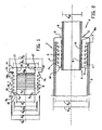
Figure 1 is a side view on a composite half of a sealing according to the invention consisting of two identical longitudinal members; and -
Figure 2 is a longitudinal cross-section of an assembly of two overlapping pipes with a sealing formed by two longitudinal members according tofigure 1 . - The half 4 of the cylindrical sealing or sealing body 44 is made of EPDM with a Shore-A hardness of 75 degrees. The sealing half 4 comprises a casing (half) 5 with an internal external main diameter of D1 (in this example 34 mm) and with at the one end an end flange 6 extending radially outwards with an outer diameter of D2 (in this example 61 mm) and with at the other end a narrowed
end portion 15, which has a diameter of D3 (in this example 45 mm), which is a little smaller than diameter D4 (in this example 48 mm) of the rest of thecasing 5. - At the outside, the
end portion 15 changes into a primary firstcircumferential rib 7a, which -as seen in the drawing- has a radialannular plane 9a oriented to the left, as well as a radialannular plane 10 oriented to the right, in which theannular plane 9a changes into radialannular plane 10 via inclined ascending annular plane 11 and convexannular plane 12. Thecircumferential rib 7a has a diameter D5 (in this example 55 mm). Behind thecircumferential rib 7a a series of substantially identical circumferential ribs 7 are integrally formed on thecasing 5, which circumferential ribs are situated at equal distances from each other and have a diameter D6 (in this example 57 mm) which is a little larger than D5. - The far right
circumferential rib 7b has a relatively narrow radialannular plane 10b, which ends in thickenedcasing portion 13 with diameter D7 (a little larger than D4, in this example 51 mm), which connects thecircumferential rib 7b to the end flange 6. - The
circumferential ribs casing 5 to the outside. They are flexible to such an extent, that some bending in the direction T is possible. - At the inner circumference of the casing convex
circumferential ribs 8 are integrally formed, which have an inner diameter of D8. The far leftcircumferential rib 8 is situated at a distance of S2 (in this example 10 mm) from the left end of thecasing 5 and in the same radial area as the far left circumferential rib 7 but one. The far leftcircumferential rib 7a is situated at a distance of S1 from the left end of thecasing 5, which amounts to approximately half S2 (in this example 5 mm). - Finally at the location of the right end a special circumferential rib 8a is integrally formed on the inner plane of the
casing 5, which rib has an inclined ascendingannular plane 14 and a circumferential axial (namely extending in axial direction, as shown)annular abutment plane 16, which ends in theradial end plane 17 of the end flange 6. The circumferential rib 8a is substantially shape-retaining because of the material and in its width or either its low height, namely rigidly against bending in axial direction of the line which the rib 8a will abut, so that theabutment plane 16 will abut the outer surface of thepipe 3 tightly and level. - In
figure 2 two sealing halves 4 are arranged in theannular space 18 formed between coaxiallyinter-engaging pipe ends pipe 2 and the outer diameter D10 ofpipe 3 are smaller than D5 and larger than D8, respectively. Furthermore D2 is almost the same as the outer diameter D9 of thepipe 2. When placing, thepipes figure 2 . The sealing halves 4 can easily be inserted from the right to the left in theannular space 18, which action is facilitated by the narrowedend portion 15 and loweredcircumferential rib 7a. - During insertion of the sealing halves 4, the
circumferential ribs widest pipe 2, and be pressed against it with their surfaces 11. This is promoted by the presence of thecircumferential ribs 8. When the sealing halves 4 are inserted so far that the end flange 6 abuts the end edge of thepipe 2, the sealing 4 will not only have sealed the leakage paths A and B, but as a result of circumferential rib 8a with theabutment plane 16 pressed against thepipe 3 and because of the thickenedportion 13 which keeps the end flange 6 against the pipe end edge, also a leakage path along C and D will be prevented to a large extent. - Because the
end plane 17 of the end flange 6 slopes conically to the outside, in case thepipes pipe 3. - It will be understood that the
pipe 3 can also be a (thicker) cable, and instead of pipe 2 a passage in a wall (wall, floor, roof) can be formed, through which the (then continuing)line 3 extends. - It appeared that with the sealing according to the invention under circumstances similar to the ones with the known plug much higher pressures can be resisted.
Claims (14)
- Assernbled sleeve-shaped sealing means (1,4) for the sealing of the annular space (18) between two partly overlapping bodies (2,3) having walls of a different diameter, such as two pipes or a line and a wail passage for it, in which the sealing means comprises a cylindrical casing (5) having an axis and being composed of two or more similar longitudinal members and an end flange (6) formed at one end of the casing, which are intended to be accommodated in the annular space and to be placed against the end edge of the widest pipe or line (2), respectively, the casing at its outer surface being provided with a number of first circumferential ribs (7) spaced apart in axial direction, and at its inner surface being provided with a number of second circumferential ribs (8) spaced apart in axial direction, characterized in that a final second circumferential rib (8a) is substantially shape-retaining and is formed at said one end of the casing at the inner circumference of the end flange (6), which rib is provided with a circumferential, axially extending annular abutment plane (16) for abutment against the narrow line or pipe, in which before use the final second circumferential rib (8a) has a largest radial height in the end plane (17) of the flange (6), thereby forming a barrier in the end plane of the flange during use, in which the end plane (17) of the end flange is formed a little conically sloping toward the outer edge.
- Assembled sleeve-shaped Sealing means according to claim 1, in which the final second circumferential rib (8a) has an inclined pilot plane (14) facing the other end.
- Assembled sleeve-shaped Sealing means according to any one of the preceding claims, in which the casing (5) between the end flange (6) and the first circumferential rib (7b) situated in front of it has a larger radial thickness than in between the other first circumferential ribs (7).
- Assembled sleeve-shaped Sealing means according to any one of the preceding claims, in which the other end (15) of the casing is narrowed in relation to the rest of the casing and is substantially cylindrical.
- Assembled sleeve-shaped Sealing means according to claim 4, in which the narrowed portion (15) extends from the other end to the next first circumferential rib (7a).
- Assembled sleeve-shaped Sealing means according to claim 4 or 5, in which the primary first circumferential rib (7a) situated closest to the other end (15) of the casing extends to a lower radial level in relation to the centre line of the cylindrical casing than the subsequent secondary first circumferential ribs (7).
- Assembled sleeve-shaped Sealing means according to any one of the preceding claims, in which the second circumferential rib (8) situated closest to the other end of the casing is situated at a distance from said other end (15) which is larger than the distance between said other end and the first circumferential rib (7a) situated closest to said other end.
- Assembled sleeve-shaped Sealing means according to claim 7, in which said second circumferential rib (8) is at least almost radially aligned with the opposite secondary first circumferential rib (7a).
- Assembled sleeve-shaped Sealing means according to any one of the preceding claims, in which the first circumferential ribs (7) are formed with a first axially oriented annular plane (9a) facing the other casing end (15), a second axially oriented annular plane (10) facing the one end and a radially oriented outer surface (11,12) connecting these planes to each other, in which the second annular plane extends radially beyond the first annular plane.
- Assembled sleeve-shaped Sealing means according to claim 9, in which the radially oriented outer surface comprises an inclined portion (11) facing the other end (15).
- Assembled sleeve-shaped Sealing means according to claim 9 and 10, in which the radially oriented outer surface (12) has a substantially convex shape in axial cross-section.
- Assembled sleeve-shaped Sealing means according to any one of the preceding claims, in which at least some of the second circumferential ribs (8) form a convex radially oriented inner surface.
- Assembled sleeve-shaped Sealing means according to any one of the preceding claims, made from a synthetic rubber with a Shore-A hardness of approximately 70 degrees or more.
- Assembly of two bodies (2,3) having walls of a different diameter which reach into each other in a coaxial manner to define an annular space to be sealed, such as two pipes of a different diameter or a line and a wall passage for it, characterized in that the annular space is sealed by means of an assembled sleeve-shaped sealing means (1,4) according to any one of the preceding claims, in which the outer diameter of the first circumferential ribs (7) and the inner diameter of the second circumferential ribs (8) are adjusted such to the outer diameter of the smallest pipe or line (3) and the inner diameter of the largest pipe or wall passage (2), that by means of pressing-in against the wall concerned of the largest pipe or passage, the circumferential ribs are sealingly clamped.
Priority Applications (1)
| Application Number | Priority Date | Filing Date | Title |
|---|---|---|---|
| DE69911137T DE69911137T3 (en) | 1998-10-16 | 1999-10-13 | Composite, sleeve-shaped sealing device |
Applications Claiming Priority (2)
| Application Number | Priority Date | Filing Date | Title |
|---|---|---|---|
| NL1010333 | 1998-10-16 | ||
| NL1010333A NL1010333C2 (en) | 1998-10-16 | 1998-10-16 | Composite sleeve-shaped sealant. |
Publications (3)
| Publication Number | Publication Date |
|---|---|
| EP0994287A1 EP0994287A1 (en) | 2000-04-19 |
| EP0994287B1 EP0994287B1 (en) | 2003-09-10 |
| EP0994287B2 true EP0994287B2 (en) | 2011-01-26 |
Family
ID=19767972
Family Applications (1)
| Application Number | Title | Priority Date | Filing Date |
|---|---|---|---|
| EP99203324A Expired - Lifetime EP0994287B2 (en) | 1998-10-16 | 1999-10-13 | Composite sleeve-shaped sealing means |
Country Status (6)
| Country | Link |
|---|---|
| EP (1) | EP0994287B2 (en) |
| AT (1) | ATE249598T1 (en) |
| DE (1) | DE69911137T3 (en) |
| DK (1) | DK0994287T3 (en) |
| ES (1) | ES2207116T3 (en) |
| NL (1) | NL1010333C2 (en) |
Cited By (1)
| Publication number | Priority date | Publication date | Assignee | Title |
|---|---|---|---|---|
| US11365833B2 (en) | 2017-03-02 | 2022-06-21 | Hauff-Technik Gmbh & Co. Kg | Press seal system for sealing against a line |
Families Citing this family (18)
| Publication number | Priority date | Publication date | Assignee | Title |
|---|---|---|---|---|
| NL1016749C2 (en) * | 2000-11-30 | 2002-05-31 | Beele Eng Bv | Sealing system. |
| DE20103785U1 (en) * | 2001-03-05 | 2001-08-09 | DTS-PRO-SYS GmbH, 18107 Rostock | Sealing sleeve |
| NL1023688C2 (en) * | 2003-06-18 | 2004-12-21 | Beele Eng Bv | System for sealing a space between an inner wall of a tubular opening and at least one tube or pipe received at least partially in the opening, the axis of which is substantially parallel to the axis of the opening. |
| DE202006012464U1 (en) * | 2006-08-12 | 2007-12-27 | Rehau Ag + Co. | cover device |
| DE202006012463U1 (en) * | 2006-08-12 | 2007-12-27 | Rehau Ag + Co. | cover device |
| GB0706259D0 (en) * | 2007-03-30 | 2007-05-09 | Thermomax Ltd | Solar collector |
| EP2372208B1 (en) * | 2010-03-25 | 2013-05-29 | Tenaris Connections Limited | Threaded joint with elastomeric seal flange |
| GB2503880B (en) * | 2012-07-09 | 2019-03-13 | Polypipe Ltd | Insert for pipes |
| EP2976562A1 (en) * | 2013-03-22 | 2016-01-27 | Ngi A/S | Coupling and use |
| JP6454853B2 (en) * | 2013-11-30 | 2019-01-23 | 丸一株式会社 | Piping joint and piping construction method using piping joint |
| CH710028A1 (en) * | 2014-08-27 | 2016-02-29 | Brugg Rohr Ag Holding | Housing arrangement for a pipe connection and sealing as well as methods for the protection of pipe joints. |
| DE102014119582B4 (en) * | 2014-12-23 | 2016-10-27 | Wedi Gmbh | Sealing insert for a water outlet |
| DE102014119584B3 (en) * | 2014-12-23 | 2016-05-19 | Wedi Gmbh | Sealing insert for a water outlet |
| WO2017053552A1 (en) * | 2015-09-23 | 2017-03-30 | Weatherford Technology Holdings, Llc | Downhole seal |
| CN107697464B (en) * | 2017-08-22 | 2019-07-23 | 武汉船用机械有限责任公司 | A kind of protective device and method of central siphon and double tube |
| US11906099B2 (en) * | 2018-03-21 | 2024-02-20 | Phoenix Environmental, Inc. | Seal on the interstice of double-walled fiberglass pipe |
| CN108488380A (en) * | 2018-04-27 | 2018-09-04 | 北京洛科瀚科技有限公司 | A kind of corrugated rubber seal of double hardness |
| DE102019110322A1 (en) * | 2019-04-18 | 2020-10-22 | Wedi Gmbh | Drain device with an adapter for connection to a pipeline |
Citations (8)
| Publication number | Priority date | Publication date | Assignee | Title |
|---|---|---|---|---|
| CH247518A (en) † | 1944-02-22 | 1947-03-15 | Pfister & Langhanss | Elastic sealing body for pipe connections. |
| DE1475807A1 (en) † | 1965-08-19 | 1969-09-18 | Ruehle Dipl Ing Alfred | Connection and sealing element for pipe connections |
| DE2203370A1 (en) † | 1972-01-25 | 1973-08-02 | Heinz Wunderlich | DEVICE FOR ANCHORING PIPELINE OUTLETS IN THE WALL |
| FR2169219A1 (en) † | 1972-01-25 | 1973-09-07 | Wunderlich Heinz | |
| US4735440A (en) † | 1985-07-05 | 1988-04-05 | Rasmussen Gmbh | Hose coupling |
| US4915422A (en) † | 1989-01-06 | 1990-04-10 | The American Brass & Iron Foundry | Pipe coupling |
| EP0448924B1 (en) † | 1990-03-28 | 1994-07-06 | Lenzing Aktiengesellschaft | Process for separating water from a diluted aqueous solution of N-methylmorpholine-N-oxide, N-methylmorpholine and/or morpholine |
| US5653542A (en) † | 1994-05-25 | 1997-08-05 | Brother Kogyo Kabushiki Kaisha | Tape cassette |
Family Cites Families (5)
| Publication number | Priority date | Publication date | Assignee | Title |
|---|---|---|---|---|
| GB1083451A (en) * | 1963-03-11 | 1967-09-13 | Allied Ironfounders Ltd | A sealing member and a pipe joint incorporating the same |
| GB1059749A (en) * | 1964-05-28 | 1967-02-22 | Bibby Foundry Ltd | Pipe seal |
| NL7500337A (en) * | 1975-01-10 | 1976-07-13 | Kleinhof Ferd | Lavatory pan flush pipe union sleeve - is plastic with end flange and internal and external sealing ribs |
| NL177516C (en) * | 1978-09-12 | 1985-10-01 | Pidou Bv | SEALING CUFF. |
| EP0139337A3 (en) * | 1983-10-19 | 1986-07-30 | Pidou B.V. | Multi-part sealing system |
-
1998
- 1998-10-16 NL NL1010333A patent/NL1010333C2/en not_active IP Right Cessation
-
1999
- 1999-10-13 AT AT99203324T patent/ATE249598T1/en not_active IP Right Cessation
- 1999-10-13 ES ES99203324T patent/ES2207116T3/en not_active Expired - Lifetime
- 1999-10-13 EP EP99203324A patent/EP0994287B2/en not_active Expired - Lifetime
- 1999-10-13 DK DK99203324T patent/DK0994287T3/en active
- 1999-10-13 DE DE69911137T patent/DE69911137T3/en not_active Expired - Lifetime
Patent Citations (8)
| Publication number | Priority date | Publication date | Assignee | Title |
|---|---|---|---|---|
| CH247518A (en) † | 1944-02-22 | 1947-03-15 | Pfister & Langhanss | Elastic sealing body for pipe connections. |
| DE1475807A1 (en) † | 1965-08-19 | 1969-09-18 | Ruehle Dipl Ing Alfred | Connection and sealing element for pipe connections |
| DE2203370A1 (en) † | 1972-01-25 | 1973-08-02 | Heinz Wunderlich | DEVICE FOR ANCHORING PIPELINE OUTLETS IN THE WALL |
| FR2169219A1 (en) † | 1972-01-25 | 1973-09-07 | Wunderlich Heinz | |
| US4735440A (en) † | 1985-07-05 | 1988-04-05 | Rasmussen Gmbh | Hose coupling |
| US4915422A (en) † | 1989-01-06 | 1990-04-10 | The American Brass & Iron Foundry | Pipe coupling |
| EP0448924B1 (en) † | 1990-03-28 | 1994-07-06 | Lenzing Aktiengesellschaft | Process for separating water from a diluted aqueous solution of N-methylmorpholine-N-oxide, N-methylmorpholine and/or morpholine |
| US5653542A (en) † | 1994-05-25 | 1997-08-05 | Brother Kogyo Kabushiki Kaisha | Tape cassette |
Cited By (1)
| Publication number | Priority date | Publication date | Assignee | Title |
|---|---|---|---|---|
| US11365833B2 (en) | 2017-03-02 | 2022-06-21 | Hauff-Technik Gmbh & Co. Kg | Press seal system for sealing against a line |
Also Published As
| Publication number | Publication date |
|---|---|
| EP0994287A1 (en) | 2000-04-19 |
| DE69911137T2 (en) | 2004-07-08 |
| ATE249598T1 (en) | 2003-09-15 |
| DE69911137D1 (en) | 2003-10-16 |
| DK0994287T3 (en) | 2004-01-05 |
| DE69911137T3 (en) | 2011-07-21 |
| NL1010333C2 (en) | 2000-04-18 |
| EP0994287B1 (en) | 2003-09-10 |
| ES2207116T3 (en) | 2004-05-16 |
Similar Documents
| Publication | Publication Date | Title |
|---|---|---|
| EP0994287B2 (en) | Composite sleeve-shaped sealing means | |
| US5662360A (en) | Interlocked restraint for a plastic pipe joining system | |
| US6126209A (en) | Pipe having an in-line bell | |
| US4702502A (en) | Gasket for making joints in corrugated plastic pipe | |
| AU658127B2 (en) | Secondarily contained fluid supply system | |
| US5463187A (en) | Flexible multi-duct conduit assembly | |
| US6352288B1 (en) | Thrust and torque resistant pipe joint | |
| US5490694A (en) | Threadless pipe coupler | |
| US20020158466A1 (en) | Self restrained pressure gasket | |
| US20070273107A1 (en) | System for sealing a space between a tubular opening and a tube | |
| CA2466605C (en) | Pipe having a water-tight in-line bell | |
| CN113454384A (en) | Piping assembly insulation and vapor barrier | |
| US5868443A (en) | Anti-rotation pipe joint | |
| ITRM970555A1 (en) | QUICK COUPLING JOINT FOR CONNECTING A SMALL INTERNAL DIAMETER FLEXIBLE HOSE TO A METALLIC PIPE OF A BRAKING SYSTEM | |
| US7104574B2 (en) | Corrugated pipe connection joint | |
| US6615860B2 (en) | Fire block conduit coupler | |
| EP1655528B1 (en) | WC pan connector | |
| US5499660A (en) | Relining pipe having pipe elements interconnected by pipe couplings | |
| KR20100071161A (en) | Socket for double wall corrugated pipe | |
| WO1999040355A1 (en) | Restrained bell and spigot fluid pipe connection | |
| EP0439313B1 (en) | Pipe joints and couplings and parts thereof | |
| EP1352191B1 (en) | Fire block conduit coupler | |
| KR200201079Y1 (en) | Rubber seal structure for manhole waterproof | |
| KR200331508Y1 (en) | connecting apparatus for pipe | |
| CA2367641A1 (en) | Fire block conduit coupler |
Legal Events
| Date | Code | Title | Description |
|---|---|---|---|
| PUAI | Public reference made under article 153(3) epc to a published international application that has entered the european phase |
Free format text: ORIGINAL CODE: 0009012 |
|
| AK | Designated contracting states |
Kind code of ref document: A1 Designated state(s): AT BE CH CY DE DK ES FI FR GB GR IE IT LI LU MC NL PT SE |
|
| AX | Request for extension of the european patent |
Free format text: AL;LT;LV;MK;RO;SI |
|
| 17P | Request for examination filed |
Effective date: 20000810 |
|
| AKX | Designation fees paid |
Free format text: AT BE CH CY DE DK ES FI FR GB GR IE IT LI LU MC NL PT SE |
|
| 17Q | First examination report despatched |
Effective date: 20020416 |
|
| GRAH | Despatch of communication of intention to grant a patent |
Free format text: ORIGINAL CODE: EPIDOS IGRA |
|
| GRAS | Grant fee paid |
Free format text: ORIGINAL CODE: EPIDOSNIGR3 |
|
| GRAA | (expected) grant |
Free format text: ORIGINAL CODE: 0009210 |
|
| AK | Designated contracting states |
Kind code of ref document: B1 Designated state(s): AT BE CH CY DE DK ES FI FR GB GR IE IT LI LU MC NL PT SE |
|
| REG | Reference to a national code |
Ref country code: GB Ref legal event code: FG4D |
|
| REG | Reference to a national code |
Ref country code: CH Ref legal event code: EP |
|
| PG25 | Lapsed in a contracting state [announced via postgrant information from national office to epo] |
Ref country code: IE Free format text: LAPSE BECAUSE OF NON-PAYMENT OF DUE FEES Effective date: 20031013 Ref country code: CY Free format text: LAPSE BECAUSE OF FAILURE TO SUBMIT A TRANSLATION OF THE DESCRIPTION OR TO PAY THE FEE WITHIN THE PRESCRIBED TIME-LIMIT Effective date: 20031013 |
|
| REF | Corresponds to: |
Ref document number: 69911137 Country of ref document: DE Date of ref document: 20031016 Kind code of ref document: P |
|
| REG | Reference to a national code |
Ref country code: IE Ref legal event code: FG4D |
|
| PG25 | Lapsed in a contracting state [announced via postgrant information from national office to epo] |
Ref country code: MC Free format text: LAPSE BECAUSE OF NON-PAYMENT OF DUE FEES Effective date: 20031031 |
|
| PG25 | Lapsed in a contracting state [announced via postgrant information from national office to epo] |
Ref country code: GR Free format text: LAPSE BECAUSE OF FAILURE TO SUBMIT A TRANSLATION OF THE DESCRIPTION OR TO PAY THE FEE WITHIN THE PRESCRIBED TIME-LIMIT Effective date: 20031210 |
|
| REG | Reference to a national code |
Ref country code: CH Ref legal event code: NV Representative=s name: DR. R.C. SALGO EUROPEAN PATENT ATTORNEY |
|
| PG25 | Lapsed in a contracting state [announced via postgrant information from national office to epo] |
Ref country code: PT Free format text: LAPSE BECAUSE OF FAILURE TO SUBMIT A TRANSLATION OF THE DESCRIPTION OR TO PAY THE FEE WITHIN THE PRESCRIBED TIME-LIMIT Effective date: 20031218 |
|
| REG | Reference to a national code |
Ref country code: DK Ref legal event code: T3 |
|
| REG | Reference to a national code |
Ref country code: SE Ref legal event code: TRGR |
|
| REG | Reference to a national code |
Ref country code: ES Ref legal event code: FG2A Ref document number: 2207116 Country of ref document: ES Kind code of ref document: T3 |
|
| PLBQ | Unpublished change to opponent data |
Free format text: ORIGINAL CODE: EPIDOS OPPO |
|
| PLBI | Opposition filed |
Free format text: ORIGINAL CODE: 0009260 |
|
| ET | Fr: translation filed | ||
| PLAX | Notice of opposition and request to file observation + time limit sent |
Free format text: ORIGINAL CODE: EPIDOSNOBS2 |
|
| REG | Reference to a national code |
Ref country code: IE Ref legal event code: MM4A |
|
| 26 | Opposition filed |
Opponent name: BEELE ENGINEERING B.V Effective date: 20040609 |
|
| NLR1 | Nl: opposition has been filed with the epo |
Opponent name: BEELE ENGINEERING B.V |
|
| PLAX | Notice of opposition and request to file observation + time limit sent |
Free format text: ORIGINAL CODE: EPIDOSNOBS2 |
|
| PLBB | Reply of patent proprietor to notice(s) of opposition received |
Free format text: ORIGINAL CODE: EPIDOSNOBS3 |
|
| PLAQ | Examination of admissibility of opposition: information related to despatch of communication + time limit deleted |
Free format text: ORIGINAL CODE: EPIDOSDOPE2 |
|
| PLAR | Examination of admissibility of opposition: information related to receipt of reply deleted |
Free format text: ORIGINAL CODE: EPIDOSDOPE4 |
|
| PLBQ | Unpublished change to opponent data |
Free format text: ORIGINAL CODE: EPIDOS OPPO |
|
| PLAB | Opposition data, opponent's data or that of the opponent's representative modified |
Free format text: ORIGINAL CODE: 0009299OPPO |
|
| R26 | Opposition filed (corrected) |
Opponent name: BEELE ENGINEERING B.V Effective date: 20040609 |
|
| RAP2 | Party data changed (patent owner data changed or rights of a patent transferred) |
Owner name: ARTECH RUBBER B.V. |
|
| NLR1 | Nl: opposition has been filed with the epo |
Opponent name: BEELE ENGINEERING B.V |
|
| PGFP | Annual fee paid to national office [announced via postgrant information from national office to epo] |
Ref country code: CH Payment date: 20050929 Year of fee payment: 7 |
|
| PGFP | Annual fee paid to national office [announced via postgrant information from national office to epo] |
Ref country code: FR Payment date: 20050930 Year of fee payment: 7 |
|
| PGFP | Annual fee paid to national office [announced via postgrant information from national office to epo] |
Ref country code: DK Payment date: 20051004 Year of fee payment: 7 |
|
| PGFP | Annual fee paid to national office [announced via postgrant information from national office to epo] |
Ref country code: SE Payment date: 20051005 Year of fee payment: 7 Ref country code: FI Payment date: 20051005 Year of fee payment: 7 |
|
| PGFP | Annual fee paid to national office [announced via postgrant information from national office to epo] |
Ref country code: GB Payment date: 20051012 Year of fee payment: 7 Ref country code: BE Payment date: 20051012 Year of fee payment: 7 |
|
| PGFP | Annual fee paid to national office [announced via postgrant information from national office to epo] |
Ref country code: ES Payment date: 20051017 Year of fee payment: 7 |
|
| PGFP | Annual fee paid to national office [announced via postgrant information from national office to epo] |
Ref country code: AT Payment date: 20051018 Year of fee payment: 7 |
|
| PGFP | Annual fee paid to national office [announced via postgrant information from national office to epo] |
Ref country code: LU Payment date: 20051027 Year of fee payment: 7 |
|
| PLAB | Opposition data, opponent's data or that of the opponent's representative modified |
Free format text: ORIGINAL CODE: 0009299OPPO |
|
| PLAB | Opposition data, opponent's data or that of the opponent's representative modified |
Free format text: ORIGINAL CODE: 0009299OPPO |
|
| R26 | Opposition filed (corrected) |
Opponent name: BEELE ENGINEERING B.V Effective date: 20040609 |
|
| NLR1 | Nl: opposition has been filed with the epo |
Opponent name: BEELE ENGINEERING B.V |
|
| PG25 | Lapsed in a contracting state [announced via postgrant information from national office to epo] |
Ref country code: FI Free format text: LAPSE BECAUSE OF NON-PAYMENT OF DUE FEES Effective date: 20061013 Ref country code: AT Free format text: LAPSE BECAUSE OF NON-PAYMENT OF DUE FEES Effective date: 20061013 |
|
| PG25 | Lapsed in a contracting state [announced via postgrant information from national office to epo] |
Ref country code: SE Free format text: LAPSE BECAUSE OF NON-PAYMENT OF DUE FEES Effective date: 20061014 |
|
| PG25 | Lapsed in a contracting state [announced via postgrant information from national office to epo] |
Ref country code: LI Free format text: LAPSE BECAUSE OF NON-PAYMENT OF DUE FEES Effective date: 20061031 Ref country code: DK Free format text: LAPSE BECAUSE OF NON-PAYMENT OF DUE FEES Effective date: 20061031 Ref country code: CH Free format text: LAPSE BECAUSE OF NON-PAYMENT OF DUE FEES Effective date: 20061031 |
|
| PGFP | Annual fee paid to national office [announced via postgrant information from national office to epo] |
Ref country code: IT Payment date: 20061031 Year of fee payment: 8 |
|
| APBP | Date of receipt of notice of appeal recorded |
Free format text: ORIGINAL CODE: EPIDOSNNOA2O |
|
| APAH | Appeal reference modified |
Free format text: ORIGINAL CODE: EPIDOSCREFNO |
|
| APBQ | Date of receipt of statement of grounds of appeal recorded |
Free format text: ORIGINAL CODE: EPIDOSNNOA3O |
|
| REG | Reference to a national code |
Ref country code: CH Ref legal event code: PL |
|
| EUG | Se: european patent has lapsed | ||
| GBPC | Gb: european patent ceased through non-payment of renewal fee |
Effective date: 20061013 |
|
| REG | Reference to a national code |
Ref country code: FR Ref legal event code: ST Effective date: 20070629 |
|
| PG25 | Lapsed in a contracting state [announced via postgrant information from national office to epo] |
Ref country code: GB Free format text: LAPSE BECAUSE OF NON-PAYMENT OF DUE FEES Effective date: 20061013 |
|
| BERE | Be: lapsed |
Owner name: *ARTECH RUBBER B.V. Effective date: 20061031 |
|
| REG | Reference to a national code |
Ref country code: ES Ref legal event code: FD2A Effective date: 20061014 |
|
| PG25 | Lapsed in a contracting state [announced via postgrant information from national office to epo] |
Ref country code: FR Free format text: LAPSE BECAUSE OF NON-PAYMENT OF DUE FEES Effective date: 20061031 Ref country code: ES Free format text: LAPSE BECAUSE OF NON-PAYMENT OF DUE FEES Effective date: 20061014 |
|
| PG25 | Lapsed in a contracting state [announced via postgrant information from national office to epo] |
Ref country code: LU Free format text: LAPSE BECAUSE OF NON-PAYMENT OF DUE FEES Effective date: 20061013 |
|
| PG25 | Lapsed in a contracting state [announced via postgrant information from national office to epo] |
Ref country code: IT Free format text: LAPSE BECAUSE OF NON-PAYMENT OF DUE FEES Effective date: 20071013 Ref country code: BE Free format text: LAPSE BECAUSE OF FAILURE TO SUBMIT A TRANSLATION OF THE DESCRIPTION OR TO PAY THE FEE WITHIN THE PRESCRIBED TIME-LIMIT Effective date: 20061031 |
|
| APBU | Appeal procedure closed |
Free format text: ORIGINAL CODE: EPIDOSNNOA9O |
|
| PLAH | Information related to despatch of examination report in opposition + time limit modified |
Free format text: ORIGINAL CODE: EPIDOSCORE2 |
|
| PLAY | Examination report in opposition despatched + time limit |
Free format text: ORIGINAL CODE: EPIDOSNORE2 |
|
| PLBC | Reply to examination report in opposition received |
Free format text: ORIGINAL CODE: EPIDOSNORE3 |
|
| PLAT | Information related to reply to examination report in opposition deleted |
Free format text: ORIGINAL CODE: EPIDOSDORE3 |
|
| PLBC | Reply to examination report in opposition received |
Free format text: ORIGINAL CODE: EPIDOSNORE3 |
|
| PLAY | Examination report in opposition despatched + time limit |
Free format text: ORIGINAL CODE: EPIDOSNORE2 |
|
| PLBC | Reply to examination report in opposition received |
Free format text: ORIGINAL CODE: EPIDOSNORE3 |
|
| PUAH | Patent maintained in amended form |
Free format text: ORIGINAL CODE: 0009272 |
|
| STAA | Information on the status of an ep patent application or granted ep patent |
Free format text: STATUS: PATENT MAINTAINED AS AMENDED |
|
| 27A | Patent maintained in amended form |
Effective date: 20110126 |
|
| AK | Designated contracting states |
Kind code of ref document: B2 Designated state(s): AT BE CH CY DE DK ES FI FR GB GR IE IT LI LU MC NL PT SE |
|
| REG | Reference to a national code |
Ref country code: NL Ref legal event code: T3 |
|
| PGFP | Annual fee paid to national office [announced via postgrant information from national office to epo] |
Ref country code: NL Payment date: 20161005 Year of fee payment: 18 Ref country code: DE Payment date: 20161018 Year of fee payment: 18 |
|
| REG | Reference to a national code |
Ref country code: DE Ref legal event code: R119 Ref document number: 69911137 Country of ref document: DE |
|
| REG | Reference to a national code |
Ref country code: NL Ref legal event code: MM Effective date: 20171101 |
|
| PG25 | Lapsed in a contracting state [announced via postgrant information from national office to epo] |
Ref country code: NL Free format text: LAPSE BECAUSE OF NON-PAYMENT OF DUE FEES Effective date: 20171101 Ref country code: DE Free format text: LAPSE BECAUSE OF NON-PAYMENT OF DUE FEES Effective date: 20180501 |