EP0993853A2 - Dispositif pour la filtration de substances liquides - Google Patents
Dispositif pour la filtration de substances liquides Download PDFInfo
- Publication number
- EP0993853A2 EP0993853A2 EP99830643A EP99830643A EP0993853A2 EP 0993853 A2 EP0993853 A2 EP 0993853A2 EP 99830643 A EP99830643 A EP 99830643A EP 99830643 A EP99830643 A EP 99830643A EP 0993853 A2 EP0993853 A2 EP 0993853A2
- Authority
- EP
- European Patent Office
- Prior art keywords
- filtering
- shaft
- container
- sleeve
- foregoing
- Prior art date
- Legal status (The legal status is an assumption and is not a legal conclusion. Google has not performed a legal analysis and makes no representation as to the accuracy of the status listed.)
- Withdrawn
Links
- 238000001914 filtration Methods 0.000 title claims abstract description 64
- 239000007788 liquid Substances 0.000 title claims abstract description 19
- 239000000126 substance Substances 0.000 title claims abstract description 19
- 239000013049 sediment Substances 0.000 claims abstract description 13
- 238000004140 cleaning Methods 0.000 claims abstract description 11
- XLYOFNOQVPJJNP-UHFFFAOYSA-N water Substances O XLYOFNOQVPJJNP-UHFFFAOYSA-N 0.000 claims description 29
- 239000004744 fabric Substances 0.000 claims description 7
- 230000002262 irrigation Effects 0.000 claims description 6
- 238000003973 irrigation Methods 0.000 claims description 6
- 229920000728 polyester Polymers 0.000 claims description 6
- 238000011144 upstream manufacturing Methods 0.000 claims description 2
- 230000001419 dependent effect Effects 0.000 claims 3
- 239000004576 sand Substances 0.000 description 9
- 239000012535 impurity Substances 0.000 description 4
- 239000003621 irrigation water Substances 0.000 description 3
- 238000009434 installation Methods 0.000 description 2
- 239000007921 spray Substances 0.000 description 2
- 244000025254 Cannabis sativa Species 0.000 description 1
- 241001465754 Metazoa Species 0.000 description 1
- 238000012423 maintenance Methods 0.000 description 1
- 238000012986 modification Methods 0.000 description 1
- 230000004048 modification Effects 0.000 description 1
- 239000011044 quartzite Substances 0.000 description 1
- 239000007787 solid Substances 0.000 description 1
- 239000000725 suspension Substances 0.000 description 1
Images


Classifications
-
- B—PERFORMING OPERATIONS; TRANSPORTING
- B01—PHYSICAL OR CHEMICAL PROCESSES OR APPARATUS IN GENERAL
- B01D—SEPARATION
- B01D29/00—Filters with filtering elements stationary during filtration, e.g. pressure or suction filters, not covered by groups B01D24/00 - B01D27/00; Filtering elements therefor
- B01D29/39—Filters with filtering elements stationary during filtration, e.g. pressure or suction filters, not covered by groups B01D24/00 - B01D27/00; Filtering elements therefor with hollow discs side by side on, or around, one or more tubes, e.g. of the leaf type
- B01D29/41—Filters with filtering elements stationary during filtration, e.g. pressure or suction filters, not covered by groups B01D24/00 - B01D27/00; Filtering elements therefor with hollow discs side by side on, or around, one or more tubes, e.g. of the leaf type mounted transversely on the tube
-
- B—PERFORMING OPERATIONS; TRANSPORTING
- B01—PHYSICAL OR CHEMICAL PROCESSES OR APPARATUS IN GENERAL
- B01D—SEPARATION
- B01D29/00—Filters with filtering elements stationary during filtration, e.g. pressure or suction filters, not covered by groups B01D24/00 - B01D27/00; Filtering elements therefor
- B01D29/62—Regenerating the filter material in the filter
- B01D29/70—Regenerating the filter material in the filter by forces created by movement of the filter element
- B01D29/74—Regenerating the filter material in the filter by forces created by movement of the filter element involving centrifugal force
-
- B—PERFORMING OPERATIONS; TRANSPORTING
- B01—PHYSICAL OR CHEMICAL PROCESSES OR APPARATUS IN GENERAL
- B01D—SEPARATION
- B01D2201/00—Details relating to filtering apparatus
- B01D2201/28—Position of the filtering element
- B01D2201/282—Filtering elements with a horizontal rotation or symmetry axis
Definitions
- the present invention relates to a device for filtering liquid substances.
- water used for irrigation purposes is normally pumped from canals, springs, rivers, etc. and must be filtered before reaching the crops to be irrigated.
- the water from these sources has a high content of impurities in suspension, such as mud, sand, grass, seeds, small animals, etc.
- impurities such as mud, sand, grass, seeds, small animals, etc.
- the nozzles that are usually used to spray the water on the crops to be irrigated have very small outlets, with a cross section area of approximately one square millimetre, for example.
- the impurities are not removed from the water immediately downstream of the pump which draws the water from the source and conveys it to the irrigation nozzles, the nozzles get clogged up very easily.
- the degree of filtering required normally varies from 40 to 100 microns, depending on the spray nozzles used.
- the oldest and most widely used filtering system comprises two filters in line: the first filter, the larger of the two, is a sand filter that acts as a precleaner to remove most of the impurities, while the second, smaller filter is a mesh or sleeve filter and makes it possible to reach the final degree of filtering.
- the filtering element In the sand filter, the filtering element consists of bed of grit (diameter 8-10 mm) or quartzite (diameter 1-2 mm), depending on the required degree of filtering. This is a vertical filter into which the dirty water flows from above, flows through the filtering bed, into a collection tank or tube and from there out of the filter.
- the filtering element is a cylinder of electro-welded wire mesh, while in the sleeve filter, the filtering element is a cylinder of polyester fabric placed over a wire mesh cylinder. If the water comes from an artesian well or from a river, it has a high content of suspended solids (sand) so another specific type of filter (cyclone separator) must be installed to separate the sand from the water.
- sand suspended solids
- the cleaning intervals of the filters are very short and, to keep them operating at acceptable levels of efficiency, they must be cleaned approximately every fifteen minutes by flowing water through them in the opposite direction for about five minutes. That means that for every hour, approximately twenty minutes are lost in cleaning the filters. Also, the water used to clean the filters cannot be used for irrigation purposes and must be thrown away.
- the cleaning interval of the sleeve filter is not sufficient to enable the reverse flow cleaning of the sand filter and so another sand filter of the same size must be installed.
- the aim of the present invention is to overcome the above mentioned disadvantages by providing a filtering device that is not only extremely functional but also relatively small in size and economical.
- the invention provides a filtering device for liquid substances characterized in that it comprises a container to which two pipes, an inlet and an outlet for a liquid substance mixed with sediment, are connected, the inside of the container mounting a shaft that rotates about a longitudinal axis and that has a coaxial cavity made in a part of it and leading out of the container at one end of the shaft, the shaft mounting in a substantially rigid manner a plurality of filtering elements and having coaxially keyed to it an impeller of a hydraulic motor housed inside the container and driven by the liquid substance mixed with sediment.
- the numeral 1 indicates as a whole a device for filtering liquid substances.
- the device 1 comprises a tank or container 2 that is substantially cylindrical in shape and that, when used, extends along a horizontal axis 3.
- the container 2 has two rounded surfaces 4 and 5 (left and right in Figure 1), having respective axial holes 6 and 7 made in them.
- the hole 6 coaxially houses a ball bearing 8 while the hole 7 coaxially houses a self-lubricating bush 9.
- the bearing 8 and the bush 9 coaxially support a shaft 10 which extends along the axis 3 and which, for the reasons explained in more detail below, has a cavity 11 coaxial to it, said cavity 11 being made in the part of the shaft 10 facing the bush 9 and leading out of the container 2 through an end portion 10' of the shaft 10 housed in the bush 9 itself.
- the part of the shaft 10 located on the left-hand side in Figure 1 has coaxially keyed to it an impeller 12 of a hydraulic motor consisting, for example, of a vane turbine 13.
- the two sides of the impeller 12 perpendicular to the axis 3 are delimited by two identical discoidal elements 14 which are coaxially housed in the container 2 and whose diameter is slightly smaller than the substantially cylindrical chamber 2' defined by the inside of the container 2.
- the cavity 15 inside the container 2 and defined by the discoidal elements 14 and by a part of the inner cylindrical surface of the container 2 communicates with a pipe 16, one end of which is connected to the container 2 and the section of it on the side connected to the container 2 being positioned in such a way that it is substantially tangential to the periphery of the impeller 12.
- the filtering elements 18 are placed side by side and are fixed to the shaft 10 in such a way that they cannot move along the shaft.
- each filtering element 18 comprises a hub or sleeve 19, substantially cylindrical in shape having an axial cavity 20 into which the shaft 10 can be fitted with a slight amount of play.
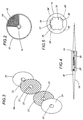
- each side of each sleeve 19 is connected to the central areas of filtering means and opposing means consisting, respectively, of a disc 23 and a disc 24, being equal in diameter, where the central areas have respective circular holes 21 and 22 slightly smaller in diameter than the sleeve 19.
- the discs 23 and 24 are made preferably of monofilament polyester netting and monofilament polyester fabric, respectively.
- the discs 23 are located in the gaps between the discs 24 and act mainly as opposing elements designed to keep the discs 24 associated with each filtering element 18 well stretched and spaced apart. In other words, their function is to keep the discs 24 in the right shape and position despite the pressure exerted on the discs 24 by the water present in the container 2.
- each sleeve 19 defined by one of said cavities 20 has grooves 26 made in it at angular intervals of 90° around the longitudinal axis of the sleeve 19 itself and extending in directions parallel to this axis, which, when the sleeve 19 is fitted to the shaft 10, is parallel to the axis 3.
- Each sleeve 19 also has another longitudinal groove 27 parallel to the grooves 26 made in a part of the surface of the cavity 20 between two adjacent grooves 26 and designed to be longitudinally engaged by a contact element consisting of a longitudinal protrusion 28 made in the lateral surface of the shaft 10 on which the sleeves 19 must be fitted.
- the protrusion may consist, for example, of a key or tab.
- the shaft 10 also has four rows of radial holes 29 made at angular intervals of 90° around its axis 3, the ends of the holes 29 inside the shaft 10 leading into the aforementioned cavity 11.
- a longitudinal middle lower portion of the container 2 communicates, through a hole that is not illustrated made in the container 2 itself, with a pipe 34 for draining the water used to clean the filter device 1.
- a pipe 34 for draining the water used to clean the filter device 1.
- a valve 35 On the pipe 34, there is a valve 35 whose function is described in more detail below.
- the filtered water reaches the grooves 26 of the sleeves 19 through the passages 26' and from the grooves 26, flows into the cavity 11 in the shaft 10 through the holes 29 and then out of the cavity 11 through the end portion 10' of the shaft 10. At this point, the water is ready to be used for irrigation purposes.
- the sediment is trapped on the outer surface of the discs 24, forming a layer which tends to gradually clog up the mesh of the fabric from which the discs 24 are made. This gradually increases the difference between the pressure of the water flowing into the container 2 and that of the water flowing out of the container 2 and raises the pressure of the water inside the container 2.
- the valve 31 When the internal pressure reaches a defined value, for example one/two BARs, checked visually or detected automatically, the valve 31 is closed and the valve 35 opened; this causes the water flowing from the pump 32 to be diverted to the vane turbine 13.
- a defined value for example one/two BARs
- the impeller 12 of the turbine 13 thus starts rotating, and the shaft 10, which is connected to it, starts turning rapidly, causing the filtering elements 18 which are rigidly mounted on the shaft 10 itself, to turn with it.
- the water flowing over the vanes of the impeller 12 forces the impeller 12 to rotate and flows continuously out of the cavity 15 through the passage between the discoidal elements 14 and the inner cylindrical surface of the container 2.
- the centrifugal force generated by the rotation of the impeller 12 detaches the sediment from the outer surfaces of the discs 24 and to mix with the water in the container 2. This water, with the sediment suspended in it, is forced out of the container 2 through the pipe 34.
- valve 31 opens again, the valve 35 closes, the vane turbine 13, together with the shaft 10 and the filtering elements 18, stops turning and the filtering device 1 is ready to filter fresh incoming water again.
- Figure 8 shows a filtering device 100 that constitutes another embodiment of the filtering device 1 described above.
- the reference numbers used in Figure 8 relative to the filtering device 100 are the same as those used to indicate the parts of the filtering device 1.
- the pipe 16 is not envisaged and the pipe 34 is connected preferably to a cylindrical portion of the container 2, substantially adjacent to the vane turbine 13; the pipe 34 is preferably vertical, extending downwards, and the section of it connected to the container 2 is fitted in such a way that it is substantially tangential to the periphery of the impeller 12.
- the filtering of the water mixed with sediment and the cleaning of the filtering elements 18 occur in the same way as described above, except that, during the cleaning operation, the valve 35 is opened but the valve 31 is not closed. Consequently, when the valve 35 is opened, the impeller 12 and the vane turbine 13 are made to turn rapidly by the negative pressure created at a portion of the impeller 12 by the water mixed with sediment flowing out through the pipe 34.
- the filtering devices 1 and 100 are considerably smaller and lighter than the conventional filtering devices most commonly used, even though the filtering devices 1 and 100 have a large filtering surface.
- the turbine 13 may be of different type from the one illustrated schematically, and the filtering elements 18 may also have a different shape from that described.
- all the details of the invention may be substituted by technically equivalent parts.
Applications Claiming Priority (2)
| Application Number | Priority Date | Filing Date | Title |
|---|---|---|---|
| IT1998BO000588A IT1304403B1 (it) | 1998-10-16 | 1998-10-16 | Dispositivo di filtratura di sostanze liquide. |
| ITBO980588 | 1998-10-16 |
Publications (2)
| Publication Number | Publication Date |
|---|---|
| EP0993853A2 true EP0993853A2 (fr) | 2000-04-19 |
| EP0993853A3 EP0993853A3 (fr) | 2000-06-21 |
Family
ID=11343458
Family Applications (1)
| Application Number | Title | Priority Date | Filing Date |
|---|---|---|---|
| EP99830643A Withdrawn EP0993853A3 (fr) | 1998-10-16 | 1999-10-11 | Dispositif pour la filtration de substances liquides |
Country Status (3)
| Country | Link |
|---|---|
| EP (1) | EP0993853A3 (fr) |
| IL (1) | IL132373A (fr) |
| IT (1) | IT1304403B1 (fr) |
Cited By (11)
| Publication number | Priority date | Publication date | Assignee | Title |
|---|---|---|---|---|
| WO2012019559A1 (fr) * | 2010-08-12 | 2012-02-16 | Fujian Newland Entech Co., Ltd. | Filtre à disque creux et filtre stratifié comprenant celui-ci |
| CN102764531A (zh) * | 2012-07-03 | 2012-11-07 | 江苏江大源生态生物科技有限公司 | 过滤器 |
| US8647516B2 (en) | 2010-09-03 | 2014-02-11 | Johnny Leon LOVE | Filtration method with self-cleaning filter assembly |
| WO2016106130A1 (fr) * | 2014-12-22 | 2016-06-30 | PRO-Equipment, Inc. | Filtre à membrane dynamique à flux croisé haute vitesse |
| US9675910B1 (en) * | 2012-03-06 | 2017-06-13 | Robert Louis Wade | Apparatus and method for cleaning of swimming pool and spa cartridge filters |
| CN109731384A (zh) * | 2019-02-20 | 2019-05-10 | 中国农业科学院蜜蜂研究所 | 成熟蜂蜜过滤装置及方法 |
| CN111167199A (zh) * | 2019-12-08 | 2020-05-19 | 陕西联智网络科技有限公司 | 一种机电一体化的废水处理设备 |
| CN111520608A (zh) * | 2020-04-20 | 2020-08-11 | 自贡联友新能源科技有限公司 | 一种带清洁功能的缓冲式压力容器 |
| CN112554992A (zh) * | 2020-11-04 | 2021-03-26 | 李冬菊 | 一种汽车机油净化用滤清器 |
| CN115920508A (zh) * | 2023-03-15 | 2023-04-07 | 江苏威泽智能科技股份有限公司 | 一种新型数控机床的过滤装置及其清洁方法 |
| CN109731384B (zh) * | 2019-02-20 | 2024-05-14 | 中国农业科学院蜜蜂研究所 | 成熟蜂蜜过滤装置及方法 |
Citations (5)
| Publication number | Priority date | Publication date | Assignee | Title |
|---|---|---|---|---|
| US4060483A (en) * | 1975-05-14 | 1977-11-29 | Barzuza Y | Method and apparatus for effecting the cleaning of a fluid filter |
| GB2076682A (en) * | 1980-03-26 | 1981-12-09 | Uhde Gmbh | Centrifugal filters |
| WO1982001666A1 (fr) * | 1980-11-13 | 1982-05-27 | Tucker Alfred D | Filtre auto-nettoyant |
| WO1988007401A1 (fr) * | 1987-04-03 | 1988-10-06 | Kemijoki Oy | Filtre a tambour a fonctionnement autonome et procede de filtrage de l'eau |
| WO1998014260A1 (fr) * | 1996-10-01 | 1998-04-09 | Davidson, Clifford, M. | Filtre |
-
1998
- 1998-10-16 IT IT1998BO000588A patent/IT1304403B1/it active
-
1999
- 1999-10-11 EP EP99830643A patent/EP0993853A3/fr not_active Withdrawn
- 1999-10-13 IL IL13237399A patent/IL132373A/en not_active IP Right Cessation
Patent Citations (5)
| Publication number | Priority date | Publication date | Assignee | Title |
|---|---|---|---|---|
| US4060483A (en) * | 1975-05-14 | 1977-11-29 | Barzuza Y | Method and apparatus for effecting the cleaning of a fluid filter |
| GB2076682A (en) * | 1980-03-26 | 1981-12-09 | Uhde Gmbh | Centrifugal filters |
| WO1982001666A1 (fr) * | 1980-11-13 | 1982-05-27 | Tucker Alfred D | Filtre auto-nettoyant |
| WO1988007401A1 (fr) * | 1987-04-03 | 1988-10-06 | Kemijoki Oy | Filtre a tambour a fonctionnement autonome et procede de filtrage de l'eau |
| WO1998014260A1 (fr) * | 1996-10-01 | 1998-04-09 | Davidson, Clifford, M. | Filtre |
Cited By (15)
| Publication number | Priority date | Publication date | Assignee | Title |
|---|---|---|---|---|
| WO2012019559A1 (fr) * | 2010-08-12 | 2012-02-16 | Fujian Newland Entech Co., Ltd. | Filtre à disque creux et filtre stratifié comprenant celui-ci |
| US8647516B2 (en) | 2010-09-03 | 2014-02-11 | Johnny Leon LOVE | Filtration method with self-cleaning filter assembly |
| US9675910B1 (en) * | 2012-03-06 | 2017-06-13 | Robert Louis Wade | Apparatus and method for cleaning of swimming pool and spa cartridge filters |
| CN102764531A (zh) * | 2012-07-03 | 2012-11-07 | 江苏江大源生态生物科技有限公司 | 过滤器 |
| US10246350B2 (en) | 2014-12-22 | 2019-04-02 | PRO-Equipment, Inc. | High velocity cross flow dynamic membrane filter |
| US9926212B2 (en) | 2014-12-22 | 2018-03-27 | PRO-Equipment, Inc. | High velocity cross flow dynamic membrane filter |
| WO2016106130A1 (fr) * | 2014-12-22 | 2016-06-30 | PRO-Equipment, Inc. | Filtre à membrane dynamique à flux croisé haute vitesse |
| US10927020B2 (en) | 2014-12-22 | 2021-02-23 | PRO-Equipment, Inc. | High velocity cross flow dynamic membrane filter |
| CN109731384A (zh) * | 2019-02-20 | 2019-05-10 | 中国农业科学院蜜蜂研究所 | 成熟蜂蜜过滤装置及方法 |
| CN109731384B (zh) * | 2019-02-20 | 2024-05-14 | 中国农业科学院蜜蜂研究所 | 成熟蜂蜜过滤装置及方法 |
| CN111167199A (zh) * | 2019-12-08 | 2020-05-19 | 陕西联智网络科技有限公司 | 一种机电一体化的废水处理设备 |
| CN111520608A (zh) * | 2020-04-20 | 2020-08-11 | 自贡联友新能源科技有限公司 | 一种带清洁功能的缓冲式压力容器 |
| CN111520608B (zh) * | 2020-04-20 | 2021-08-06 | 自贡联友新能源科技有限公司 | 一种带清洁功能的缓冲式压力容器 |
| CN112554992A (zh) * | 2020-11-04 | 2021-03-26 | 李冬菊 | 一种汽车机油净化用滤清器 |
| CN115920508A (zh) * | 2023-03-15 | 2023-04-07 | 江苏威泽智能科技股份有限公司 | 一种新型数控机床的过滤装置及其清洁方法 |
Also Published As
| Publication number | Publication date |
|---|---|
| ITBO980588A0 (it) | 1998-10-16 |
| IL132373A (en) | 2002-04-21 |
| IT1304403B1 (it) | 2001-03-19 |
| IL132373A0 (en) | 2001-03-19 |
| ITBO980588A1 (it) | 2000-04-16 |
| EP0993853A3 (fr) | 2000-06-21 |
Similar Documents
| Publication | Publication Date | Title |
|---|---|---|
| CA2592670C (fr) | Tamis a contre-courant equipe d'un mecanisme a circulation a cyclone | |
| US4707258A (en) | Disk filter | |
| JP3839074B2 (ja) | 逆流洗浄式フィルタ | |
| US6156213A (en) | Embedded spin-clean cartridge-type water filters | |
| EP2767321B1 (fr) | Filtre autonettoyant | |
| GB2035115A (en) | Backwashable fluid filter | |
| CN109789347B (zh) | 具有用于防止旁路水用于反洗的旁路水控制的框架型盘式过滤器 | |
| EP0993853A2 (fr) | Dispositif pour la filtration de substances liquides | |
| CN105126414B (zh) | 离心式自清洁滤器 | |
| CN101163552B (zh) | 具有隔流收集腔的赫诺式涡轮离心机 | |
| US4897192A (en) | Rotary filtration device | |
| US5076942A (en) | Filter | |
| US4422938A (en) | Backwashing-type filtering apparatus | |
| KR101952310B1 (ko) | 관내 삽입형 여과기 | |
| CN1191106C (zh) | 污水澄清用的过滤装置 | |
| US3817446A (en) | Pitot pump with centrifugal separator | |
| KR102608983B1 (ko) | 역세 기능이 구비된 회전 필터 여과장치 | |
| JP7125689B2 (ja) | ストレーナ | |
| JPH05137912A (ja) | 固定スクリーンフイルタ | |
| WO1984004293A1 (fr) | Dispositif de purification de milieux liquides comme des eaux usees | |
| US4054528A (en) | Self-cleaning strainer or filter | |
| KR102527637B1 (ko) | 여과장치가 구비된 밸브실 | |
| AU2018376937B2 (en) | Immersed device for swimming pool filtration | |
| CN209392818U (zh) | 压载水过滤器 | |
| JPS586487Y2 (ja) | ストレ−ナ |
Legal Events
| Date | Code | Title | Description |
|---|---|---|---|
| PUAI | Public reference made under article 153(3) epc to a published international application that has entered the european phase |
Free format text: ORIGINAL CODE: 0009012 |
|
| AK | Designated contracting states |
Kind code of ref document: A2 Designated state(s): AT BE CH CY DE DK ES FI FR GB GR IE IT LI LU MC NL PT SE |
|
| AX | Request for extension of the european patent |
Free format text: AL;LT;LV;MK;RO;SI |
|
| PUAL | Search report despatched |
Free format text: ORIGINAL CODE: 0009013 |
|
| AK | Designated contracting states |
Kind code of ref document: A3 Designated state(s): AT BE CH CY DE DK ES FI FR GB GR IE IT LI LU MC NL PT SE |
|
| AX | Request for extension of the european patent |
Free format text: AL;LT;LV;MK;RO;SI |
|
| 17P | Request for examination filed |
Effective date: 20001213 |
|
| AKX | Designation fees paid |
Free format text: AT BE CH CY DE DK ES FI FR GB GR IE IT LI LU MC NL PT SE |
|
| 17Q | First examination report despatched |
Effective date: 20020510 |
|
| STAA | Information on the status of an ep patent application or granted ep patent |
Free format text: STATUS: THE APPLICATION HAS BEEN WITHDRAWN |
|
| 18W | Application withdrawn |
Effective date: 20030922 |