EP0993666B1 - Signalübertragungseinrichtung - Google Patents
Signalübertragungseinrichtung Download PDFInfo
- Publication number
- EP0993666B1 EP0993666B1 EP98938665A EP98938665A EP0993666B1 EP 0993666 B1 EP0993666 B1 EP 0993666B1 EP 98938665 A EP98938665 A EP 98938665A EP 98938665 A EP98938665 A EP 98938665A EP 0993666 B1 EP0993666 B1 EP 0993666B1
- Authority
- EP
- European Patent Office
- Prior art keywords
- transmitter
- transmitters
- rotation
- receivers
- angle
- Prior art date
- Legal status (The legal status is an assumption and is not a legal conclusion. Google has not performed a legal analysis and makes no representation as to the accuracy of the status listed.)
- Expired - Lifetime
Links
- 230000005540 biological transmission Effects 0.000 claims description 24
- 230000003287 optical effect Effects 0.000 claims description 15
- 238000000034 method Methods 0.000 claims description 10
- 230000003111 delayed effect Effects 0.000 claims description 8
- 230000002457 bidirectional effect Effects 0.000 claims description 3
- 230000001419 dependent effect Effects 0.000 claims description 2
- 230000001960 triggered effect Effects 0.000 claims description 2
- 238000005070 sampling Methods 0.000 claims 3
- 230000004069 differentiation Effects 0.000 claims 1
- 238000011144 upstream manufacturing Methods 0.000 claims 1
- 230000004888 barrier function Effects 0.000 description 16
- 230000011514 reflex Effects 0.000 description 14
- 230000008054 signal transmission Effects 0.000 description 5
- 230000002745 absorbent Effects 0.000 description 4
- 239000002250 absorbent Substances 0.000 description 4
- 238000010586 diagram Methods 0.000 description 3
- 238000011156 evaluation Methods 0.000 description 3
- 238000005259 measurement Methods 0.000 description 3
- 238000011161 development Methods 0.000 description 2
- 238000005553 drilling Methods 0.000 description 2
- 238000009434 installation Methods 0.000 description 2
- BASFCYQUMIYNBI-UHFFFAOYSA-N platinum Chemical compound [Pt] BASFCYQUMIYNBI-UHFFFAOYSA-N 0.000 description 2
- 238000012546 transfer Methods 0.000 description 2
- 230000002411 adverse Effects 0.000 description 1
- 238000006243 chemical reaction Methods 0.000 description 1
- 238000013461 design Methods 0.000 description 1
- 238000005516 engineering process Methods 0.000 description 1
- 238000002955 isolation Methods 0.000 description 1
- 230000007257 malfunction Effects 0.000 description 1
- 239000011159 matrix material Substances 0.000 description 1
- 229910000679 solder Inorganic materials 0.000 description 1
Images


Classifications
-
- G—PHYSICS
- G08—SIGNALLING
- G08C—TRANSMISSION SYSTEMS FOR MEASURED VALUES, CONTROL OR SIMILAR SIGNALS
- G08C19/00—Electric signal transmission systems
-
- H—ELECTRICITY
- H04—ELECTRIC COMMUNICATION TECHNIQUE
- H04B—TRANSMISSION
- H04B10/00—Transmission systems employing electromagnetic waves other than radio-waves, e.g. infrared, visible or ultraviolet light, or employing corpuscular radiation, e.g. quantum communication
- H04B10/80—Optical aspects relating to the use of optical transmission for specific applications, not provided for in groups H04B10/03 - H04B10/70, e.g. optical power feeding or optical transmission through water
- H04B10/801—Optical aspects relating to the use of optical transmission for specific applications, not provided for in groups H04B10/03 - H04B10/70, e.g. optical power feeding or optical transmission through water using optical interconnects, e.g. light coupled isolators, circuit board interconnections
Definitions
- the present invention relates to a signal transmission device, and a method for data transmission between a rotating in a fixed system.
- Such signal transmission devices are common used in measurement technology to, for example, measurement data from a rotating shaft on a fixed connection line respectively.
- helicopters those for example for a single sheet control of the Rotor blades measurement and control data between the fixed Helicopter cell and the rotor are replaced.
- a known system for the transmission of electrical Signals between a fixed and a rotating System is a mechanical slip ring with sliding contacts.
- a mechanical slip ring is subject to one Wear. If there are several data channels to be transmitted a considerable axial for the arrangement of the contact tracks or radial installation space is required. In addition, the mutual Isolation of the individual tracks with multiple data channels very complex.
- the object of the invention is therefore an arrangement and a method of transferring data on one or more Data channels between a rotating system and to create a fixed system, the arrangement is wear-free, and a high data transfer rate in a small installation space allows. This object is achieved by the device according to claim 1 and the method according to claim 10.
- the transmitter and receiver each evenly distributed in annular areas are (at equal angular distances from each other), so that with a full rotation of the rotating system one after the other every sender faces every receiver.
- There is one Angle of rotation sensor for determining the angle of rotation between rotating and fixed system as well a transmitter switching device for the angle of rotation Assignment of data channels to transmitters provided.
- the transmitter and receiver are in the tangential direction arranged one behind the other. So there is only one geometric track per direction of transmission on all Data channels are transmitted. It is advantageous that only little space is needed and that the individual receiver are relatively small and a simple geometric shape can have.
- the incoming signals on the data channels and the signal of the rotation angle sensor are on the Transmitter switching device guided. This becomes dependent on the angle of rotation each data channel is assigned to the transmitter, which is opposite to the recipient who has this data channel assigned.
- the transmitter switching device assigns data channels to transmitters depending on the Angle of rotation range too.
- An uninterrupted data transmission can be advantageous Be achieved by the number the transmitter corresponds to twice the number of receivers, and the tangential extent of each receiver slightly is larger than the circular arc between two neighboring ones Stations.
- the transmitter and receiver are each even distributed, i.e. at equal angular intervals from each other same radius area arranged (with axial arrangement from sending and receiving system). Through this configuration the invention ensures that for each At the time, each receiver faces at least one transmitter.
- the transmitter and receiver are optical Act as a basis, i.e. the signals are transmitted as light signals become. There is no optical transmission mechanical wear on it, and it may be due to the high fundamental frequency high transmission rates can be achieved.
- LEDs as transmitters and photodiodes as receivers are common and therefore inexpensive.
- the rotation angle sensor must distinguish exactly as many states as there are combinations of transmitters and receivers gives. With 8 transmitters, for example, 8 states must be used corresponding to 8 circle sectors, each with 45 ° sector angle be distinguishable. It is advantageous if the angle of rotation sensor without a complex evaluation mechanism or A / D conversion directly generates a digital signal.
- a rotation angle sensor with trained as reflex light barriers, for example Scanning elements and one of the scanning elements opposite scan track distinguishes, for example between 8 equally large rotation angle ranges and delivers a corresponding 3-bit signal.
- the transmitter switchover device a suitably programmed programmable Logic IC (e.g. Lattice Type 1016), in which the Evaluation logic is integrated very compactly. It is advantageous that there are only short delay times, and that overall only a few contact points (e.g. solder joints) required are. It is also possible to use simple ones Logic gates (TTL), which then switch accordingly are.
- a suitably programmed programmable Logic IC e.g. Lattice Type 1016
- TTL Logic gates
- both sender and receiver is provided enables bidirectional data transmission.
- the direction of transmission is annular Track provided on which the transmitter and receiver are arranged are.
- a particularly critical moment is when a broadcaster leaves the area of one recipient and the neighboring one Immersed transmitter in the area. If the tangential extension of the receiver is slightly larger than the circular arc between two neighboring transmitters, are for a short time two transmitters in the reception area, so that switching without Signal interruption can take place. Will in this time range at any time between the transmitters switched, there may be a malfunction if that Switching on and switching off does not take place exactly at the same time. For this reason, it is advantageous if only then is switched when the date "Low" is currently being transmitted becomes. If the transmitters are LEDs, “Low” does not result in any Light emitted. While “Low” is present, it is still transmitting active transmitter no light off, and switching to the next station. The next "high” is then from then transmit active transmitter.
- the "low” state can be reliably recognized as follows :
- the status "Low” is indicated by a subsequent positive edge ended.
- the transferred Signal has the property that "Low” is always for a certain one Minimum duration applies. During this minimum period (Time interval before a positive edge) the state is "Low” always on. It is therefore advantageous to Transmitter switching device both an undelayed as well to supply a delayed signal, the time delay is not greater than the said minimum duration.
- Switching from one transmitter to the next will triggered by a positive edge of the undelayed signal, while the delayed signal for transmission to the assigned transmitter is routed.
- a useful delay time in practice takes e.g. 30 ns.
- a simple geometric structure is achieved that the two parts rotatable against each other are disc-shaped, and face each other axially.
- the invention provides a wear-free, reliable and compact data transfer between enables a rotating and a fixed system, which is very advantageous for a helicopter for data transmission between a rotor and the helicopter cell can be used.
- Fig. 1 shows schematically the geometric arrangement of 8 LEDs T1 - T8 and the retro-reflective sensors A1, A2, B, C on a circular disk-shaped circuit board 10 of the sending System.
- the circuit board 10 can, for example, rotate with it be connected to a main helicopter rotor, the axis of rotation the circuit board in the center designated by 16 cuts orthogonally.
- the board 10 has a bore in the region of the axis of rotation 17 on.
- the 8 LEDs acting as optical transmitters are in each case equal angular distances of 45 ° from one another arranged with 12 designated circle radius.
- the LEDs T1 - T8 have a certain radial extension, so that along the circle radius 12 an annular disc Area arises in which the LEDs are arranged.
- the reflected light barriers are on a second circle radius 14 A1, A2, B, C of a rotation angle sensor arranged.
- Fig. 2 shows schematically a circuit board 18 of a receiving one Systems, on which 4 photodiodes R1 - R4 and a scanning track are arranged.
- the scan track has one light reflecting part 20 and a light absorbing part Part 22 and is arranged in the same radius area as the reflected light barriers on the board 10 (Fig. 1).
- the photodiodes R1 - R4, which act as optical receivers are at the same radial distance from the center of the disc, i.e. arranged in the same annular disk-shaped area, like the LEDs T1-T8 of the sending system 10 (Fig. 1).
- With 19 is a bore for a central passage.
- the reflex light barriers A1, A2, B, C and the opposite ones Scanning track are part of a rotation angle sensor.
- the structure and functioning of this so-called Angle of rotation sensor are not the subject of this invention.
- the main function of this rotation angle sensor is that eight, each 45 ° enclosing in a simple manner Sector sectors can be distinguished from each other.
- the circuit board 18 at a rotation of the board 10 (sending system) the circuit board 18 (receiving system) scans each one of the reflex light barriers A1, A2, B, C a limit between reflecting area 20 and absorbing area Area 22 of the scan track.
- the output of the respective reflex light barrier changes in the process.
- the reflex light barriers are at the rotation angle positions 0 °, 45 °, 135 ° and Arranged 270 °.
- the outputs of the retro-reflective sensors on the rotation angle positions 45 ° (A1) and 135 ° (A2) are through a logic gate with an "exclusive or” link with each other connected. They form together with the exits of the reflex light barriers at the angle of rotation 0 ° (B) and 270 ° (C) a 3-bit signal. Any value of this signal corresponds to one of the 8 rotation angle ranges.
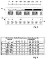
- Fig. 5 shows a sketch of the geometric development the arrangements according to Figures 1 and 2. In the process corresponds to a rotation of the sending system 10 according to FIG the direction of rotation indicated by an arrow in Fig. 1 relative movement of the sending system 10 the receiving system 18 to the right. It is too note that the views of Fig. 1 and Fig. 2 in face the assembled state. In the shown in Fig. 5 Position are 2 transmitters at the same time in the area of a recipient. The reflex light barrier B is just on the border from the absorbent area 22 to the reflective area 20.
- This Position is the middle position of the rotation angle range 1 (0 ° - 45 °) of the table according to Fig. 6.
- the in the last Column of Fig. 6 specified transmitters T1, T3, T5, T7 active while the transmitters T2, T4, T6, T8 are not currently active are.
- x1 is one of the 4 transmitter-side input signals the transmitter switch 34 (Fig. 3).
- the Transmitter switch 34 also has an input for that delayed by a delay element 32 by the time ⁇ t Signal x ⁇ t1 and another input from the reflex light barrier A2 (36).
- the undelayed signal x1 serves for switching the transmitter while the delayed signal x ⁇ t1 is carried and transmitted to the respective transmitter.
- the reflex light barrier A2 enters at time t0 the absorbent portion 22 of the scan track. Your exit changes from "High” to "Low”. That is the first condition for switching channels.
- the second condition for that Transmitter switchover is fulfilled at time t1: on the undelayed Signal x1 changes from “Low” to "High”, so a positive edge.
- the signal has the property that a "low” or "high” state is always for one certain minimum duration applies. So with the undelayed Signal x1 detected a positive edge, so it can be reliable conclude that the delayed signal x ⁇ t1 the "Low” state for the duration of the delay time ⁇ t is present if the time delay is not greater is than the said minimum duration.
- the conditions for Transmitter switch from T1 to T8 fulfilled and it can be done.
- the transmitter T1 is switched off and the transmitter T8 is switched on.
- the transmitter switching device 34 is, for example a programmable logic IC (PAL), in which the evaluation logic is filed.
- PAL programmable logic IC
- the switchover therefore takes place during a "low” is currently being transmitted and is therefore insensitive towards different time behavior of the individual Channel. If you switched over during a "high”, and the transmitter to be switched on, for example, a little later calls than the switch-off, it would lead to a signal interruption cause, so that on the receiving end incorrectly a "low” would be recognized.
- the signal comes with a small, im essentially corresponding to the delay time ⁇ t, delay on.
- a prerequisite for the functioning of the signal transmission device is that in that for switching channels time range in question a "low" is transmitted. It is assumed that the signals to be transmitted have this property.
- FIG. 3 finally shows a block diagram of a signal transmission direction according to the invention.
- the single ones Signals 26 are transmitted to line receiver 30 on the transmitter side guided.
- the transmitter switch 34 receives both the undelayed signals, as well as those through the delay element 32 delayed signals. Depending on the angle range, that of the individual reflex light barriers 36 (A1, A2, B, C) is detected, it controls the correct one Transmitter 38 on.
- the optical transmission path 24 is located between the sending system 10 and the receiving system 18. T1 - T8).
- the resistors 42, 48, 50 are necessary for a high quality of the signals.
- the received signals are amplified by the amplifier 44 and fed via the comparator 46 to the line driver 52, which has a signal output 28 for each data channel.
- the advantages of the invention are independent of the Number of data channels to be transmitted. For example it is possible to transmit 5 data channels if 10 Transmitter and 5 receivers are provided, and by the rotation angle sensor 10 angular ranges are distinguishable.
Landscapes
- Physics & Mathematics (AREA)
- General Physics & Mathematics (AREA)
- Electromagnetism (AREA)
- Engineering & Computer Science (AREA)
- Computer Networks & Wireless Communication (AREA)
- Signal Processing (AREA)
- Optical Communication System (AREA)
- Arrangements For Transmission Of Measured Signals (AREA)
Description
- Fig. 1
- eine kreisförmige Platine mit 8 Sendern und 4 Reflexlichtschranken (sendendes System),
- Fig. 2
- eine kreisförmige Platine mit 4 Empfängern und einer Abtastspur (empfangendes System),
- Fig. 3
- ein Blockschaltbild der Übertragungsstrecke,
- Fig. 4
- ein Signalablaufdiagramm,
- Fig. 5
- eine Skizze der geometrischen Abwicklung einer erfindungsgemäßen Anordnung,
- Fig. 6
- eine Zuordnungsmatrix von Drehwinkelbereichen und Sender/ Empfänger Kombinationen.
Die Widerstände 42, 48, 50 sind notwendig für eine hohe Qualität der Signale. Die empfangenen Signale werden vom Verstärker 44 verstärkt und über den Komparator 46 dem Leitungstreiber 52 zugeleitet, welcher für jeden Datenkanal einen Signalausgang 28 aufweist.
- T1
- Sender (LED)
- T2
- Sender (LED)
- T3
- Sender (LED)
- T4
- Sender (LED)
- T5
- Sender (LED)
- T6
- Sender (LED)
- T7
- Sender (LED)
- T8
- Sender (LED)
- R1
- Empfänger (Fotodiode)
- R2
- Empfänger (Fotodiode)
- R3
- Empfänger (Fotodiode)
- R4
- Empfänger (Fotodiode)
- A1
- Reflexlichtschranke
- A2
- Reflexlichtschranke
- B
- Reflexlichtschranke
- C
- Reflexlichtschranke
- 10
- Platine, sendendes System
- 12
- Spur, Datenübertragung
- 14
- Spur, Drehwinkelsensor
- 16
- Drehzentrum
- 17
- Bohrung
- 18
- Platine, empfangendes System
- 19
- Bohrung
- 20
- Abtastspur, reflektierend
- 22
- Abtastspur, absorbierend
- 24
- optische Übertragungsstrecke
- 26
- Signaleingang
- 28
- Signalausgang
- 30
- Leitungsempfänger
- 32
- Verzögerungsglied
- 34
- Senderumschalteinrichtung (PAL)
- 36
- Reflexlichtschranke (A1, A2, B oder C)
- 38
- LED (T1, T2, T3, T4, T5, T6, T7 oder T8)
- 40
- Fotodiode (R1, R2, R3 oder R4)
- 42
- Widerstand
- 44
- Verstärker
- 46
- Komparator
- 48
- Widerstand
- 50
- Widerstand
- 52
- Leitungstreiber
Claims (10)
- Signalübertragungseinrichtung zur Übertragung von Daten auf einem oder mehreren Datenkanälen zwischen einem rotierenden System und einem feststehenden System, wobei auf einem sendenden System (10), welches das rotierende oder das feststehende sein kann, mehrere Sender (T1 - T8) und auf einem gegenüberliegenden empfangenden System (18) ein oder mehrere Empfänger (R1 - R4) angeordnet sind, wobei die Sender und Empfänger jeweils auf ringförmigen Bereichen gleichmäßig verteilt angeordnet sind, so daß bei einer vollen Drehung des rotierenden Systems nacheinander jeder Sender jedem Empfänger gegenübersteht, mit einem Drehwinkelsensor (A1, A2, B, C, 20, 22) zur Bestimmung des Drehwinkels zwischen rotierendem und feststehendem System und einer Senderumschalteinrichtung (34) zur drehwinkelabhängigen Zuordnung von Datenkanälen zu Sendern, dadurch gekennzeichnet, daß senderseitig vor der Senderumschalteinrichtung (34) ein Verzögerungsglied (32) für ankommende Signale vorhanden ist.
- Signalübertragungseinrichtung nach Anspruch 1, dadurch gekennzeichnet, daß die Anzahl der Sender (T1 - T8) der doppelten Anzahl der Empfänger (R1 - R4) entspricht, und die tangentiale Erstreckung jedes Empfängers geringfügig größer ist, als der Kreisbogen zwischen zwei benachbarten Sendern.
- Signalübertragungseinrichtung nach Anspruch 1 oder 2, dadurch gekennzeichnet, daß die Sender (T1 - T8) optische Sender und die Empfänger (R1 - R4) optische Empfänger sind.
- Signalübertragungseinrichtung nach Anspruch 3, dadurch gekennzeichnet , daß die optischen Sender (T1 - T8) LEDs sind und die optischen Empfänger (R1 - R4) Fotodioden sind.
- Signalübertragungseinrichtung nach einem der Ansprüche 1 bis 4, dadurch gekennzeichnet, daß der Drehwinkelsensor mehrere Abtastelemente (A1, A2, B, C) und eine den Abtastelementen gegenüberliegende geschlossene Codespur (20, 22) aufweist, so daß eine, der Senderanzahl entsprechende Anzahl von gleichgroßen Drehwinkelbereichen unterscheidbar ist.
- Signalübertragungseinrichtung nach Anspruch 5 dadurch gekennzeichnet, daß acht Sender und vier Empfänger vorhanden sind, und daß der Drehwinkelsensor auf einem ersten Teil (10) jeweils ein Abtastelement an den Drehwinkelstellungen 0° (B), 45° (A1), 135° (A2), 270° (C) aufweist, und die Codespur in zwei verschiedene jeweils 180° umschließende Bereiche (20, 22) unterteilt ist, und daß ein Logikgatter mit einer "Exklusiv Oder" Verknüpfung vorhanden ist, durch den die Ausgänge der Abtastelemente an den Drehwinkelstellungen 45° (A1) und 135° (A2) verknüpft sind.
- Signalübertragungseinrichtung nach einem der Ansprüche 1 bis 6, dadurch gekennzeichnet, daß die Senderumschalteinrichtung (34) ein programmierbarer Logik IC ist.
- Signalübertragungseinrichtung nach einem der Ansprüche 1 bis 7 dadurch gekennzeichnet, daß zur bidirektionalen Datenübertragung sowohl im feststehenden als auch in rotierenden System jeweils Sender und Empfänger vorhanden sind.
- Signalübertragungseinrichtung nach einem der Ansprüche 1 bis 8 dadurch gekennzeíchnet, daß das drehende System in einem Hubschrauberrotor und das feststehende System in einer Hubschrauberzelle angeordnet ist.
- Verfahren zur - insbesondere optischen - Übertragung von Daten auf einem oder mehreren Datenkanälen mit einer Signalübertragungseinrichtung nach einem der Ansprüche 1 bis 9 wobei die senderseitig auf den Datenkanälen ankommenden Signale und das Signal des Drehwinkelsensors auf die Senderumschalteinrichtung (34) geführt werden, und von der Senderumschalteinrichtung jeder Datenkanal jeweils. dem Sender zugeordnet wird, der in einem bestimmten Drehwinkelbereich dem diesem Datenkanal zugeordneten Empfänger gegenüberliegt, dadurch gekennzeichnet, daß die Umschaltung eines Datenkanals von einem Sender auf den nächsten Sender dann erfolgt, wenn ein bestimmter Drehwinkel überschritten wird, und auf dem Datenkanal das Datum "Low" übertragen wird, daß der Senderumschalteinrichtung (34) die auf den Datenkanälen ankommenden Signale sowohl unverzögert (x1 als auch durch das Verzögerungsglied verzögert (xΔt1) zugeführt werden, daß die Umschaltung von einem Sender (T1) auf den nächsten Sender (T8) durch eine positive Flanke des unverzögerten Signals ausgelöst wird, und daß das verzögerte Signal auf den jeweils zugeordneten Sender geleitet wird.
Applications Claiming Priority (3)
| Application Number | Priority Date | Filing Date | Title |
|---|---|---|---|
| DE19728314 | 1997-07-03 | ||
| DE19728314A DE19728314A1 (de) | 1997-07-03 | 1997-07-03 | Signalübertragungseinrichtung |
| PCT/EP1998/003938 WO1999001850A2 (de) | 1997-07-03 | 1998-06-27 | Signalübertragungseinrichtung |
Publications (2)
| Publication Number | Publication Date |
|---|---|
| EP0993666A2 EP0993666A2 (de) | 2000-04-19 |
| EP0993666B1 true EP0993666B1 (de) | 2002-09-18 |
Family
ID=7834450
Family Applications (1)
| Application Number | Title | Priority Date | Filing Date |
|---|---|---|---|
| EP98938665A Expired - Lifetime EP0993666B1 (de) | 1997-07-03 | 1998-06-27 | Signalübertragungseinrichtung |
Country Status (3)
| Country | Link |
|---|---|
| EP (1) | EP0993666B1 (de) |
| DE (2) | DE19728314A1 (de) |
| WO (1) | WO1999001850A2 (de) |
Families Citing this family (7)
| Publication number | Priority date | Publication date | Assignee | Title |
|---|---|---|---|---|
| US6385367B1 (en) * | 2000-07-31 | 2002-05-07 | Northrop Grumman Corporation | Parallel data transmission through segmented waveguides of large diameter |
| DE10102278B4 (de) * | 2001-01-18 | 2004-10-28 | Raytheon Marine Gmbh | Datenübertragungsstrecke an einer n.360° Lagerung |
| DE10344875A1 (de) * | 2003-09-26 | 2005-04-28 | Siemens Ag | Datenübertragungsverfahren und Optischer Drehübertrager mit Durchführung |
| EP1810617B1 (de) * | 2006-01-18 | 2008-12-03 | Kabushiki Kaisha Toshiba | Röntgen-CT-Gerät und Verknüpfungssystem zur Kommunikation von medizinischen Daten |
| DE102006059442B8 (de) * | 2006-12-15 | 2009-07-02 | Siemens Ag | Vorrichtung zur optischen Datenübertragung |
| DE102007050079B3 (de) * | 2007-10-19 | 2008-09-18 | Dmt Gmbh | Vermessungskreisel |
| US8758184B2 (en) | 2010-08-20 | 2014-06-24 | Redviking Group, Llc | Transmission test system |
Family Cites Families (14)
| Publication number | Priority date | Publication date | Assignee | Title |
|---|---|---|---|---|
| DE2237695A1 (de) * | 1972-07-31 | 1974-02-21 | Siemens Ag | Einrichtung zur uebertragung von daten zwischen teilen elektrischer maschinen |
| JPS5746543A (en) * | 1980-09-03 | 1982-03-17 | Hitachi Ltd | Light signal transmission device |
| DD215348B1 (de) * | 1983-05-30 | 1986-12-24 | Buchholz Hans Joachim | Vorrichtung zur beruehrungslosen digitalen datenuebertragung |
| DE3600260A1 (de) * | 1986-01-08 | 1987-07-09 | Bosch Gmbh Robert | Schaltungsanordnung zur messwertuebertragung an fahrzeugraedern |
| DD246212A1 (de) * | 1986-02-17 | 1987-05-27 | Thaelmann Schwermaschbau Veb | Anordnung von sende- und empfangselementen zur digitalen datenuebertragung |
| US5019814A (en) * | 1987-05-13 | 1991-05-28 | Bently Nevada Corp. | Wireless data coupling system and method |
| US4906992A (en) * | 1988-02-22 | 1990-03-06 | Dynamics Research Corporation | Single track absolute encoder |
| US5016961A (en) * | 1989-12-14 | 1991-05-21 | Ampex Corporation | Optical apparatus for electrically inter-coupling rotating and stationary devices |
| DE4010067A1 (de) * | 1990-03-29 | 1991-10-02 | Rohde & Schwarz | Sonar-ortungsanlage insbesondere fuer u-boote |
| IL98421A (en) * | 1991-06-09 | 1995-07-31 | Elscint Ltd | Optical communication link |
| JP3643384B2 (ja) * | 1992-01-14 | 2005-04-27 | 株式会社東芝 | X線断層撮影装置 |
| IL114234A0 (en) * | 1995-06-20 | 1996-08-04 | Jolt Ltd | Method and apparatus for combining data received by a plurality of receivers |
| DE19543559A1 (de) * | 1995-11-22 | 1997-05-28 | Schleifring & Apparatebau Gmbh | Kapazitives Übertragungssystem |
| DE19643451A1 (de) * | 1996-02-27 | 1997-08-28 | Petri Ag | Verfahren und Vorrichtung zur berührungslosen Übertragung elektrischer Energie und von Daten in Kraftfahrzeugen |
-
1997
- 1997-07-03 DE DE19728314A patent/DE19728314A1/de not_active Withdrawn
-
1998
- 1998-06-27 DE DE59805628T patent/DE59805628D1/de not_active Expired - Fee Related
- 1998-06-27 EP EP98938665A patent/EP0993666B1/de not_active Expired - Lifetime
- 1998-06-27 WO PCT/EP1998/003938 patent/WO1999001850A2/de not_active Ceased
Also Published As
| Publication number | Publication date |
|---|---|
| WO1999001850A3 (de) | 1999-03-25 |
| DE59805628D1 (de) | 2002-10-24 |
| WO1999001850A2 (de) | 1999-01-14 |
| EP0993666A2 (de) | 2000-04-19 |
| DE19728314A1 (de) | 1999-01-07 |
Similar Documents
| Publication | Publication Date | Title |
|---|---|---|
| EP0334018B1 (de) | Positionsgeber | |
| DE3625599C2 (de) | ||
| DE2357061C2 (de) | Einrichtung zur Abgabe von gleichmäßigen Impulsen bei bestimmten Winkelstellungen einer drehbaren Welle und zur Bildung von wenigstens einem Bezugssignal | |
| DE3601516C2 (de) | ||
| EP2063230B1 (de) | Optische Positionsmesseinrichtung | |
| DE19633744C2 (de) | Ringgraph in einem elektrischen Antriebssystem | |
| EP1852741A1 (de) | Verfahren und Vorrichtung zur Identifizierung von Wechselobjektiven | |
| EP0019129A2 (de) | Einrichtung zur Stellungsdetektion insbesondere zur Winkelstellungsdetektion | |
| EP0819913A1 (de) | Verfahren und Vorrichtung zur Positionierung von nicht-geradlinigen bewegten insbesondere rotierenden Maschinenteilen | |
| DE3441429A1 (de) | Optischer drehcodierer | |
| EP4080252B1 (de) | Lichtvorhang | |
| EP0993666A2 (de) | Signalübertragungseinrichtung | |
| DE3609211A1 (de) | Optischer winkelgeber | |
| DE69931424T2 (de) | Vorrichtung zur Drehwinkelmessung | |
| DE69004527T2 (de) | Verfahren zum Feststellen von Rollenstörungen in Rollenherdofensystemen. | |
| DE3243956A1 (de) | Positionsgeber zur lagebestimmung linear verfahrbarer maschinenteile | |
| EP0348816B1 (de) | Digitaler Lagesignalgeber | |
| DE8816086U1 (de) | Vorrichtung zur Positionierung eines Sternrades | |
| DE3200204A1 (de) | Optisches messgeraet | |
| DE3146724A1 (de) | "inkrementalkodierer, insbesondere fuer die umsetzung einer winkelbewegung in eine digitalinformation" | |
| EP0993591B1 (de) | Drehwinkelsensor | |
| EP1192369A1 (de) | Vorrichtung zum erfassen einer stellung eines stellelements | |
| EP2072011B1 (de) | Anordnung aus zwei zueinander rotativ bewegbaren Elementen | |
| DE19960890A1 (de) | Codiereinrichtung | |
| EP0551585B1 (de) | Drehbarer Codierer |
Legal Events
| Date | Code | Title | Description |
|---|---|---|---|
| PUAI | Public reference made under article 153(3) epc to a published international application that has entered the european phase |
Free format text: ORIGINAL CODE: 0009012 |
|
| 17P | Request for examination filed |
Effective date: 19991008 |
|
| AK | Designated contracting states |
Kind code of ref document: A2 Designated state(s): DE FR GB IT |
|
| GRAG | Despatch of communication of intention to grant |
Free format text: ORIGINAL CODE: EPIDOS AGRA |
|
| 17Q | First examination report despatched |
Effective date: 20020308 |
|
| GRAG | Despatch of communication of intention to grant |
Free format text: ORIGINAL CODE: EPIDOS AGRA |
|
| GRAH | Despatch of communication of intention to grant a patent |
Free format text: ORIGINAL CODE: EPIDOS IGRA |
|
| GRAH | Despatch of communication of intention to grant a patent |
Free format text: ORIGINAL CODE: EPIDOS IGRA |
|
| GRAA | (expected) grant |
Free format text: ORIGINAL CODE: 0009210 |
|
| AK | Designated contracting states |
Kind code of ref document: B1 Designated state(s): DE FR GB IT |
|
| PG25 | Lapsed in a contracting state [announced via postgrant information from national office to epo] |
Ref country code: IT Free format text: LAPSE BECAUSE OF FAILURE TO SUBMIT A TRANSLATION OF THE DESCRIPTION OR TO PAY THE FEE WITHIN THE PRE;WARNING: LAPSES OF ITALIAN PATENTS WITH EFFECTIVE DATE BEFORE 2007 MAY HAVE OCCURRED AT ANY TIME BEFORE 2007. THE CORRECT EFFECTIVE DATE MAY BE DIFFERENT FROM THE ONE RECORDED.SCRIBED TIME-LIMIT Effective date: 20020918 Ref country code: GB Free format text: LAPSE BECAUSE OF FAILURE TO SUBMIT A TRANSLATION OF THE DESCRIPTION OR TO PAY THE FEE WITHIN THE PRESCRIBED TIME-LIMIT Effective date: 20020918 Ref country code: FR Free format text: LAPSE BECAUSE OF NON-PAYMENT OF DUE FEES Effective date: 20020918 |
|
| REG | Reference to a national code |
Ref country code: GB Ref legal event code: FG4D Free format text: NOT ENGLISH |
|
| REF | Corresponds to: |
Ref document number: 59805628 Country of ref document: DE Date of ref document: 20021024 |
|
| GBV | Gb: ep patent (uk) treated as always having been void in accordance with gb section 77(7)/1977 [no translation filed] |
Effective date: 20020918 |
|
| EN | Fr: translation not filed | ||
| PLBE | No opposition filed within time limit |
Free format text: ORIGINAL CODE: 0009261 |
|
| STAA | Information on the status of an ep patent application or granted ep patent |
Free format text: STATUS: NO OPPOSITION FILED WITHIN TIME LIMIT |
|
| 26N | No opposition filed |
Effective date: 20030619 |
|
| PG25 | Lapsed in a contracting state [announced via postgrant information from national office to epo] |
Ref country code: DE Free format text: LAPSE BECAUSE OF NON-PAYMENT OF DUE FEES Effective date: 20040101 |