EP0993579B1 - Beleuchtungssystem und dessen anwendung - Google Patents
Beleuchtungssystem und dessen anwendung Download PDFInfo
- Publication number
- EP0993579B1 EP0993579B1 EP98933012A EP98933012A EP0993579B1 EP 0993579 B1 EP0993579 B1 EP 0993579B1 EP 98933012 A EP98933012 A EP 98933012A EP 98933012 A EP98933012 A EP 98933012A EP 0993579 B1 EP0993579 B1 EP 0993579B1
- Authority
- EP
- European Patent Office
- Prior art keywords
- light
- emitter
- distributor
- instrument
- light emitter
- Prior art date
- Legal status (The legal status is an assumption and is not a legal conclusion. Google has not performed a legal analysis and makes no representation as to the accuracy of the status listed.)
- Expired - Lifetime
Links
Images


Classifications
-
- G—PHYSICS
- G02—OPTICS
- G02B—OPTICAL ELEMENTS, SYSTEMS OR APPARATUS
- G02B6/00—Light guides; Structural details of arrangements comprising light guides and other optical elements, e.g. couplings
- G02B6/0001—Light guides; Structural details of arrangements comprising light guides and other optical elements, e.g. couplings specially adapted for lighting devices or systems
- G02B6/0011—Light guides; Structural details of arrangements comprising light guides and other optical elements, e.g. couplings specially adapted for lighting devices or systems the light guides being planar or of plate-like form
- G02B6/0033—Means for improving the coupling-out of light from the light guide
- G02B6/0035—Means for improving the coupling-out of light from the light guide provided on the surface of the light guide or in the bulk of it
- G02B6/0036—2-D arrangement of prisms, protrusions, indentations or roughened surfaces
-
- A—HUMAN NECESSITIES
- A61—MEDICAL OR VETERINARY SCIENCE; HYGIENE
- A61B—DIAGNOSIS; SURGERY; IDENTIFICATION
- A61B17/00—Surgical instruments, devices or methods, e.g. tourniquets
- A61B17/02—Surgical instruments, devices or methods, e.g. tourniquets for holding wounds open; Tractors
-
- G—PHYSICS
- G02—OPTICS
- G02B—OPTICAL ELEMENTS, SYSTEMS OR APPARATUS
- G02B6/00—Light guides; Structural details of arrangements comprising light guides and other optical elements, e.g. couplings
- G02B6/0001—Light guides; Structural details of arrangements comprising light guides and other optical elements, e.g. couplings specially adapted for lighting devices or systems
- G02B6/0005—Light guides; Structural details of arrangements comprising light guides and other optical elements, e.g. couplings specially adapted for lighting devices or systems the light guides being of the fibre type
- G02B6/0008—Light guides; Structural details of arrangements comprising light guides and other optical elements, e.g. couplings specially adapted for lighting devices or systems the light guides being of the fibre type the light being emitted at the end of the fibre
-
- G—PHYSICS
- G02—OPTICS
- G02B—OPTICAL ELEMENTS, SYSTEMS OR APPARATUS
- G02B6/00—Light guides; Structural details of arrangements comprising light guides and other optical elements, e.g. couplings
- G02B6/0001—Light guides; Structural details of arrangements comprising light guides and other optical elements, e.g. couplings specially adapted for lighting devices or systems
- G02B6/0005—Light guides; Structural details of arrangements comprising light guides and other optical elements, e.g. couplings specially adapted for lighting devices or systems the light guides being of the fibre type
- G02B6/001—Light guides; Structural details of arrangements comprising light guides and other optical elements, e.g. couplings specially adapted for lighting devices or systems the light guides being of the fibre type the light being emitted along at least a portion of the lateral surface of the fibre
-
- G—PHYSICS
- G02—OPTICS
- G02B—OPTICAL ELEMENTS, SYSTEMS OR APPARATUS
- G02B6/00—Light guides; Structural details of arrangements comprising light guides and other optical elements, e.g. couplings
- G02B6/0001—Light guides; Structural details of arrangements comprising light guides and other optical elements, e.g. couplings specially adapted for lighting devices or systems
- G02B6/0011—Light guides; Structural details of arrangements comprising light guides and other optical elements, e.g. couplings specially adapted for lighting devices or systems the light guides being planar or of plate-like form
- G02B6/0033—Means for improving the coupling-out of light from the light guide
- G02B6/0035—Means for improving the coupling-out of light from the light guide provided on the surface of the light guide or in the bulk of it
- G02B6/0038—Linear indentations or grooves, e.g. arc-shaped grooves or meandering grooves, extending over the full length or width of the light guide
-
- A—HUMAN NECESSITIES
- A61—MEDICAL OR VETERINARY SCIENCE; HYGIENE
- A61B—DIAGNOSIS; SURGERY; IDENTIFICATION
- A61B90/00—Instruments, implements or accessories specially adapted for surgery or diagnosis and not covered by any of the groups A61B1/00 - A61B50/00, e.g. for luxation treatment or for protecting wound edges
- A61B90/30—Devices for illuminating a surgical field, the devices having an interrelation with other surgical devices or with a surgical procedure
- A61B2090/309—Devices for illuminating a surgical field, the devices having an interrelation with other surgical devices or with a surgical procedure using white LEDs
-
- G—PHYSICS
- G02—OPTICS
- G02B—OPTICAL ELEMENTS, SYSTEMS OR APPARATUS
- G02B6/00—Light guides; Structural details of arrangements comprising light guides and other optical elements, e.g. couplings
- G02B6/0001—Light guides; Structural details of arrangements comprising light guides and other optical elements, e.g. couplings specially adapted for lighting devices or systems
- G02B6/0011—Light guides; Structural details of arrangements comprising light guides and other optical elements, e.g. couplings specially adapted for lighting devices or systems the light guides being planar or of plate-like form
- G02B6/0033—Means for improving the coupling-out of light from the light guide
- G02B6/0058—Means for improving the coupling-out of light from the light guide varying in density, size, shape or depth along the light guide
- G02B6/0061—Means for improving the coupling-out of light from the light guide varying in density, size, shape or depth along the light guide to provide homogeneous light output intensity
-
- H—ELECTRICITY
- H01—ELECTRIC ELEMENTS
- H01H—ELECTRIC SWITCHES; RELAYS; SELECTORS; EMERGENCY PROTECTIVE DEVICES
- H01H2219/00—Legends
- H01H2219/054—Optical elements
- H01H2219/062—Light conductor
-
- H—ELECTRICITY
- H01—ELECTRIC ELEMENTS
- H01H—ELECTRIC SWITCHES; RELAYS; SELECTORS; EMERGENCY PROTECTIVE DEVICES
- H01H2221/00—Actuators
- H01H2221/07—Actuators transparent
Definitions
- the present invention relates to applications of a light delivery system as a portion of a surgical instrument.
- DE-A1-4234050 discloses an instrument for inspecting the interior of a nostril as shown in Figure 1 thereof, and which may be used for aiding a surgical procedure there.
- the instrument comprises a handle and a blade portion connected to the handle for opening the nostril.
- a light emitter extends through the handle and blade portion so that it emits light only from the end of the emitter where it protrudes from the instrument.
- DE-U1-8600868 discloses a microsurgical forceps for aiding a surgical procedure.
- the forceps comprise a handle and a blade portion connected to the handle.
- This document discloses the light emitter extending through a tube and again light is only emitted from the end of the tube.
- an instrument for aiding a surgical procedure comprising a handle and a retractor arm having one end connected to the handle and another end remote from the one end, characterized by an elongated light emitter extending along the length of the retractor arm, and a connector for connecting the light emitter to a light distributor, the light emitter having light extracting formations along at least a portion of the length of the light emitter.
- the arrangement according to the present invention enables a higher level of illumination to be achieved.
- the light emitter may be substantially transparent. Also the light emitter may be oriented at an angle with respect to the handle. In a further preferred embodiment the retractor arm may be oriented at an angle with respect to the handle.
- the retractor arm may include a generally curved cross-section.
- the light extracting formations may comprise a printed pattern on a surface of the light emitter. It is also preferred that the light extracting formations are along substantially the entire length of the light emitter.
- attachment means may be provided for attaching the light emitter to the retractor arm such that the light emitter and the retractor arm are substantially parallel.
- the attachment means may comprise for example clips.
- the light distributor may comprise an optic light guide cable.
- This cable may be rigid or flexible.
- FIGs 1 to 10, 12 to 17 and 19 to 23B are presented as examples useful for understanding the present invention, embodiments of which are shown in figures 11 and 18.
- FIGs. 4A and 4B illustrate a suction/blower device 100 having an externally mounted light delivery system 2.
- Fig. 4A shows a light delivery system 2 detached from suction/blower device 100
- Fig. 4B shows light delivery system 2 attached to suction/blower device 100.
- device 100 can take many forms including a surgical instrument, as will be illustrated below.
- Light delivery system 2 is generally comprised of a light emitter 10, a light distributor 60, and an attachment means 80.
- Light emitter 10 focuses light of varying intensity in a predetermined direction or pattern. As a result, an associated viewing field is illuminated with a predetermined light characteristic.
- Light distributor 60 e.g., optic light pipe
- Attachment means 80 provides a support structure for coupling light delivery system 2 to device 100.
- attachment means 80 may include tabs, hooks or the like.
- Light emitter 10 is comprised of a transparent or translucent light emitting material of any suitable type, including acrylic, polycarbonate, glass, epoxy, resins or the like. Emitter 10 may be substantially flat, suitably curved, may be formed of single or multiple layers, and may have different thicknesses and shapes. Moreover, emitter 10 may be flexible, or rigid, and may be made out of a variety of compounds. It should also be appreciated that emitter 10 may be hollow, filled with liquid, air, or be solid, and may have holes or ridges formed therein.
- Figs. 1 and 2 show a section B of light emitter 10.
- Light extracting formations including deformities, disruptions or lenses may be provided on one or more selected light surface areas 20 on one or more sides 21 or edges 23 of emitter 10.
- the term light extracting formation is to mean any change in the shape or geometry of the surface and/or coating or surface treatment that causes a portion of the light to be emitted.
- Fig. 3A schematically shows one such light surface area 20 on which a pattern of light extracting deformities or disruptions 22 is provided. The pattern of light extracting deformities or disruptions 22 shown in Fig.
- 3A includes a variable pattern which breaks up the light rays such that the internal angle of reflection of a portion of the light rays will be great enough to cause the light rays either to be emitted out of emitter 10 through the side or sides on which the light extracting deformities or disruptions 22 are provided or reflected back through the emitter 10 and emitted out the other side thereof.
- Light extracting formations can be produced in a variety of manners, for example, by providing a painted pattern, an etched pattern, a machined pattern, a printed pattern, a hot stamped pattern, a molded pattern, a curved surface (i.e., lens), a diffraction grating, a prismatic surface or the like on selected light surface areas 20 of emitter 10.
- An ink or printed pattern may be applied for example by pad printing, silk screening, ink jet, heat transfer film process or the like.
- the deformities or disruptions may also be printed on a sheet or film which is used to apply the deformities or disruptions to light surface area 20. This sheet or film may become a permanent part of emitter 10 for example by attaching or otherwise positioning the sheet or film against one or both sides of the emitter light surface area similar to the sheet or film 24 shown in Figs. 1 and 2 in order to produce a desired effect.
- the light output of emitter 10 can be controlled.
- the light extracting formations may be used to control the direction and/or percent of light emitted from any area of emitter 10. For instance, less and/or smaller size deformities 22 may be placed on emitter 10 in areas where less light output is wanted. Conversely, a greater percentage of and/or larger deformities 22 may be placed on emitter 10 in areas where greater light output is desired.
- Varying the percentages and/or size of deformities 22 in different areas of emitter 10 is necessary in order to provide a uniform light output distribution. For example, the amount of light traveling through light emitter 10 will ordinarily be greater in areas closer to the light source than in other areas further removed from the light source.
- a pattern of light extracting deformities 22 may be used to adjust the light variances within the emitter, for example, by providing a denser concentration of light extracting deformities with increased distance from the light source thereby resulting in a more uniform light output distribution from light emitter 10.
- the deformities 22 may also be used to control the output ray angle distribution of the emitted light to suit a particular application.
- light extracting formations are suitably provided in addition to or in lieu of the patterns of light extracting deformities 22 shown in Fig. 3A.
- other light extracting formations include lenses, prismatic surfaces, depressions or raised surfaces of various shapes using more complex shapes in a mold pattern may be molded, etched, stamped, thermoformed, hot stamped or the like into or on one or more surface areas (e.g., sides and edges) of the light emitter.
- Lenses e.g., pillow lenses
- Figs. 3B and 3C show areas 26 on which prismatic surfaces 28 or depressions 30 are formed in the emitter surface area, whereas Fig.
- 3D shows prismatic or other reflective or refractive surfaces 32 formed on the exterior of the emitter surface area.
- the prismatic surfaces, depressions or raised surfaces will cause a portion of the light rays contacted thereby to be emitted from the light emitter.
- the angles of the prisms, depressions or other surfaces may be varied to direct the light in different directions to produce a desired light output distribution or effect, or to project a spot image or pattern of light to a specific area or region.
- the reflective or refractive surfaces may have shapes or a pattern with no specific angles to reduce moire or other interference effects.
- the light rays emitted from the emitter may provide generally shadow less or homogenous light.
- the emitter may simultaneously illuminate a 3-D object from a plurality of sides.
- a back reflector 34 (including trans reflectors) may be attached or positioned against one side of the panel member 14 of Fig. 1 using a suitable adhesive 36 or other method in order to improve light output efficiency of light emitter 10 by reflecting the light emitted from that side back through the panel for emission through the opposite side.
- a pattern of light extracting deformities 22, 28, 30 and/or 32 may be provided on one or both sides of the light emitter in order to change the path of the light so that the internal critical angle is exceeded and a portion of the light is emitted from one or both sides of the light emitter.
- a transparent film, sheet or plate member 24 may be attached or positioned against the side or sides of the emitter from which light is emitted using a suitable adhesive 36 or other method in order to produce a desired effect.
- Member 24 may be used to further improve the uniformity of the light output distribution.
- member 24 may be a colored film, a diffuser, or a label or display, a portion of which may be a transparent overlay that may be colored and/or have text or an image thereon.
- the adhesive is preferably applied only along the side edges of the emitter, and if desired the end edge opposite light transition areas, but not over the entire surface area or areas of the emitter because of the difficulty in consistently applying a uniform coating of adhesive to the panel. Also, the adhesive changes the internal critical angle of the light in a less controllable manner than the air gaps 40 (see Fig. 2) which are formed between the respective surfaces of the emitter and the back reflector 34 and/or member 24 when only adhered along the peripheral edges. Additionally, longer emitters are achievable when air gaps 40 are used. If adhesive were to be used over the entire surface, the pattern of deformities could be adjusted to account for the additional attenuation in the light caused by the adhesive.
- the light emitter disclosed herein may be used for a great many different applications including for example LCD back lighting or lighting in general, decorative and display lighting, automotive lighting, dental lighting, phototherapy, photodynamic therapy, or other medical lighting, membrane switch lighting, and sporting goods and apparel lighting or the like.
- the emitter may be formed such that the deformities are transparent without a back reflector. This allows the emitter to be used such that the application is viewed through the transparent emitter.
- the light that is transmitted by light distributor 60 to light emitter 10 may be emitted along the entire length of light emitter 10 or from one or more light output areas along the length of the panel as desired to produce a desired light output distribution to fit a particular application.
- Light distributor 60 is a formed light conduit adapted to propagate light therethrough via internal reflection.
- light distributor 60 takes the form of an optic light pipe.
- Light distributor 60 includes an interface 64 and a connecting member 62.
- Interface 64 interfaces light distributor 60 with light emitter 10.
- Connecting member 62 facilitates connection of light distributor 60 with light source 90 (described below). It should be appreciated that light distributor 60, light emitter 64, and light source 90 may be formed as one unitary member without interface 64 and connecting member 62.
- Light source 90 may take many forms as will be discussed below.
- light source 90 is generally comprised of a generator 92 and a cable 94.
- Generator 92 may be, for example, a 300 Watt Xenon light source.
- Cable 94 includes a connecting member 96, which mates with connecting member 62 of light distributor 60.
- light source 90 illustrated in Figs. 4A and 4B is shown solely for the purpose of illustrating an embodiment of the present invention.
- light source 90 may also be of other suitable types including, an arc lamp, an incandescent bulb (which also may be colored, filtered or painted), a lens end bulb, a line light, a halogen lamp, a light emitting diode (LED), a chip from an LED, a neon bulb, a fluorescent tube; a laser or laser diode, or any other suitable light source.
- light source 90 may take the form of any of the types disclosed in U.S. Patent Nos. 4,897,771 and 5,005,108 , assigned to the same assignee as the present application.
- the light source may be a multiple colored LED, or a combination of multiple colored radiation sources in order to provide a desired colored or white light output distribution.
- a plurality of colored lights such as LEDs of different colors (red, blue, green) or a single LED emitting a selected spectrum may be employed to create white light or any other colored light output distribution by varying the intensities of each individual colored light.
- Attachment means 80 is suitably molded as an integral part of light distributor 60 (Fig. 4A), attaches to both the light distributor and the associated device (Fig. 4C), or forms a part of device 100.
- attachment means 80 is fixed to light distributor 60, wherein gripping means 84 are provided for attaching light delivery system 2 to device 100.
- Attachment means 80 allows light delivery system 2 to be easily and conveniently attached to and detached from suction/blower device 100. As a result, light delivery system 2 is easily replaced where sterilization is required.
- one form of attachment means 80 includes engagement means 82 and 84 for fixing light delivery system 2 to a device.
- engagement means 82 are engagable with light distributor 60
- engagement means 84 are engagable with a portion of the device.
- engagement means 82 and/or engagement means 84 are suitably integral with light distributor 60 and the device, respectively.
- engagement means 82 and/or engagement means 84 will preferably provide for convenient removal of light delivery system 2 from the device. For instance, in the embodiment shown in Figs.
- engagement means 84 takes the form of a clamp, which allows for simple attachment and detachment of light delivery system 2 from device 100. It should be appreciated that engagement means 82 and 84 may take the form of other suitable fastening members including cables, snaps, clips, tabs, adhesives, and the like.
- Device 100 includes a tube 70 having a tip portion 76.
- Tip portion 76 is comprised of a plurality of openings 78, which are in communication with tube 70.
- Light emitter 10 is suitably dimensioned to receive tip portion 76, when light delivery system 2 is attached to device 100 (Fig. 4B). It should be noted that light emitter 10 is suitably formed to provide diffuse light in directions transverse to the longitudinal axis of device tip portion 76, and to provide direct light in a direction generally parallel to the longitudinal axis of tip portion 76. As indicated above, the direct light provides maximum illumination on the material being suctioned or blown. At the same time, the diffuse light provides sufficient, but not over bright, illumination of the area surrounding the material being suctioned or blown. As a result, the user's vision of the material being suctioned or blown is not impaired.
- Device 101A is a surgical instrument typically used to remove material (e.g., fluid or tissue) from a surgeons field of view. In this respect, device 101A suctions or blows the obscuring material.
- Device 101A is generally comprised of a light emitter 110, a light distributor 160 and air passageway(s) 170.
- Light distributor 160 includes a connecting member 162 dimensioned to receive a mating connecting member 196 from cable 194. Cable 194 is connected to a light source (not shown).
- light distributor 160 not only carries light to light emitter 110, but also provides a support structure for suction/blower device 101A.
- light distributor 160 includes a light distribution member 161, which is constructed of a rigid material and formed into a suitable shape for a user to conveniently hold device 101A.
- Light distribution member 161 transmits light and defines passageway(s) 170.
- Passageway(s) 170 are generally tubular hollow channels formed along the length of light distributor 160.
- Figs. 5B and 5C illustrate two different embodiments for light distributor 160.
- Passageway(s) 170 provides a conduit for air, or other gas or fluid.
- Light distributor 160 also includes an outer layer 163.
- Outer layer 163 may take the form of a heat-shrinked film, coating or tubing. Outer layer 163 provides a protective layer for light distribution member 161. Similarly, an inner layer (not shown) may line the inner surface of light distribution member 161. The outer and inner layers protect the internal light propagation from impairment (e.g., blood or other materials that can cause light loss). It should be appreciated that light distributor 160 may be constructed of a plurality of walls of varying thickness. The walls may take the form of a film, coating or tubing. Moreover, the film, coating or tubing may extend along the full length of light distributor 160, or only along a portion thereof.
- a connector 172 is provided to receive a mating connector from a hose 174.
- Hose 174 is connected to a vacuum generating means (not shown), where device 101A is used for suction, or is connected to a blower means (not shown), where device 101A is used for blowing.
- Light emitter 110 is located at the tip end of device 101A, and surrounds passageway(s) 170.
- Light emitter 110 is suitably formed to provide diffuse light in directions transverse to the longitudinal axis of device 101A, and to provide direct light in a direction generally parallel to the longitudinal axis of device 101A. In this way, the direct light provides maximum illumination on the material being suctioned or blown.
- the diffuse light provides sufficient, but not over bright, illumination of the area surrounding the material being suctioned or blown. As a result, the user's vision of the material being suctioned or blown is not impaired.
- light distributor 160 and light emitter 110 form an integral part of the suction/blowing device 101A, and thus eliminate the need for an external lighting device mounted to the suction/blowing device, a lighting device mounted elsewhere in an operating room, or a hand held lighting device.
- FIG. 6 illustrates an alternative embodiment of suction/blower device 101A.
- Suction/blower device 101B is similar in many respects to suction/blower device 101A ; however, light emitter 110 and light distributor 160 are disposable in this embodiment.
- suction/blower 101B is generally comprised of a light emitter 110, a rigid body member 150, a light distributor 160 having a fixed portion 160A and a detachable portion 160B, and a tube 170.
- Body member 150 is constructed of a rigid material (e.g., plastic) and formed into a suitable shape for a user to conveniently hold device 101B.
- Body member 150 surrounds fixed portion 160A of light distributor 160.
- Fixed portion 160A includes a connecting member 162. Fixed portion 160A and detachable portion 160B are connected at interface 166.
- a hollow channel is formed along the length of portions 160A and 160B to provide tube 170.
- Light emitter 110 is optionally detachable from light distributor 160 at interface 166.
- suction/blower device 101B has the advantage of having a detachable light emitter 110 and light distributor 160. This allows for convenient replacement of the portions of device 101 B which may require sterilization. As a result, only an inexpensive and small portion of device 101B is disposed, thus saving the expense of replacing the entire suction/blower device 101B.
- Fig. 7 illustrates another suction/blower device 102.
- Device 102 is generally comprised of a light emitter 310, a light distributor 360 and a tube 370.
- Light distributor 360 has a connecting member 362 dimensioned to receive a mating connecting member 396 from cable 394. Cable 394 is connected to a light source (not shown). It is important to note that light distributor 360 not only carries light to light emitter 310, but also provides a support structure for suction/blower device 102.
- light distributor 360 is constructed of a rigid material and formed into a suitable shape for a user to conveniently hold device 102.
- a hollow channel is formed along the length of light distributor 360 to provide tube 370.
- Light distributor 360 is preferably formed of an inexpensive plastic material.
- Tube 370 includes a connector 372, dimensioned to receive a mating connector from a hose 374.
- Hose 374 is connected to a vacuum generating means (not shown), where device 102 is used for suction, or is connected to a blower means (not shown), where device 102 is used for blowing.
- Light emitter 310 is located at tip 368 of light distributor 360, and surrounds tube 370.
- Light emitter 310 is suitably formed to provide diffuse light in directions transverse to the longitudinal axis of tip 368, and to provide direct light in a direction generally parallel to the longitudinal axis of tip 368. In this way, the direct light provides maximum illumination on the material being suctioned or blown.
- the diffuse light provides sufficient, but not over bright, illumination of the area surrounding the material being suctioned or blown. As a result, the user's vision of the material being suctioned or blown is not impaired.
- light distributor 360 is easily and conveniently attached to and detached from cable 394 and hose 374. As a result, light delivery system 202 is easily replaced where sterilization is required.
- Electrosurgical pencil device 103 is used to destroy tissue by burning the tissue with a cauterizing tip.
- Device 103 is generally comprised of a light emitter 410, a light distributor 460 and a cauterizing tip 470.
- Light distributor 460 has a connecting member 462 dimensioned to receive a mating connecting member 496 from a cable 494. Cable 494 is connected to a light source (not shown). It is important to note that light distributor 460 not only conducts light to light emitter 410, but also provides a support structure for device 103. In this respect, light distributor 460 is constructed of a rigid material and formed into a suitable shape for a user to conveniently hold device 103.
- a channel is formed along the length of light distributor 460 to provide a passageway for electrical conductor 474.
- Electrical conductor 474 connects to cauterizing tip 470, to provide power thereto.
- Light emitter 410 is suitably formed to provide diffuse light in directions transverse to the longitudinal axis of tip 470, and to provide direct light in a direction generally parallel to the longitudinal axis of tip 470. In this way, the direct light provides maximum illumination on the material being cauterized. At the same time, the diffuse light provides sufficient, but not over bright, illumination of the area surrounding the material being cauterized. As a result, the user's vision of the material being cauterized is not impaired.
- Tray 104 for illuminating a bodily structure (e.g., vein, artery, finger, or small organ).
- Tray 104 is generally comprised of a light distributor 560 and a light emitter 510.
- Light distributor 560 includes a connecting member 562 dimensioned to receive a mating connecting member 596 from a cable 594. Cable 594 is connected to a light source (not shown). It is important to note that light distributor 560 not only conducts light to light emitter 510, but also provides a support base for tray 104. In this respect, light distributor 560 is constructed of a rigid material and formed into a suitable shape for receiving a generally U-shaped light emitter 510.
- Light emitter 510 is shaped to receive a bodily structure, and thoroughly illuminate it. In this respect, light is emitted in all directions from the surface of light emitter 510.
- Fig. 9B illustrates a cross-sectional view of tray 104 with a vein/artery 570 located on tray 104 for examination. Light emitter 510 illuminates an obstruction 572 in vein/artery 570.
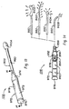
- Figs. 10A and 10B show a stabilizer device 105.
- Stabilizer device 105 is generally comprised of light emitters 610A, 610B and 610C, and a light distributor 660.
- Light distributor 660 includes a central portion 670, arm portions 672, and connecting member 662. Connecting member 662 is dimensioned to receive a mating connecting member 696 from a cable 694 (such as a light pipe). Cable 694 is connected to a light source (not shown). It is important to note that light distributor 660 not only carries light to light emitters 610A, 610B and 610C, but also provides a support structure for stabilizer device 105.
- light distributor 660 is constructed of a rigid material and formed into a suitable shape for a user to conveniently hold device 102.
- Light emitters 610A, 610B and 610C provide different lighting conditions.
- light emitter 610A may includes a lens 611 for providing direct focused light on incision work area I.
- Light emitter 610B is formed along the periphery defined by central portion 670 and arm portions 672.
- Light emitter 610B provides indirect diffuse light for incision work area I.
- Light emitter 610C is formed along the lower edge (i.e., bottom) of central portion 670 and arm portions 672.
- Light emitter 610C may provide indirect diffuse light or glowing light for transillumination of a bodily structure.
- stabilizer device 105 may be suitably arranged to attach (e.g., using a clip or other attachment means) to a metal stabilizer having the same general shape as stabilizer device 105.
- the strength of the material forming stabilizer device 105 may not sufficient for a particular application. Accordingly, the metal stabilizer provides the desired strength.
- Retractor device 106A is comprised of a retractor member 770A and a light delivery system 702A.
- Retractor member 770A includes a horizontal portion 772, a vertical portion 774, and a support member 776.
- Support member 776 is arranged between horizontal portion 772 and a rigid mount (not shown).
- Light delivery system 702A is mounted to the front face of vertical portion 774, and includes a light distributor 760A and a light emitter 710A.
- Light distributor 760A bends to follow the general shape of retractor member 770A, and receives light from a light source (not shown).
- a suitable adhesive may be used to attach light delivery system 702A to vertical portion 774.
- Light emitter 710A provides diffuse or directional light into the work area.
- Retractor device 106B is generally comprised of a retractor member 770B and a light delivery system 702B.
- Retractor member 770B is a rake retractor having a plurality of prongs.
- Light delivery system 702B includes an attachment member 780B, light distributor 760B, and light emitter 710B.
- Attachment member 780B has engagement means 784B for attaching light delivery system 702B to retractor member 770B.
- Light distributor 760B receives light from a light source (not shown).
- Light emitter 710B includes a top portion 711B and a side portion 713B. Light emitter 710B provides diffuse or directional light into the work area.
- Retractor device 106C is a rake retractor formed of a translucent material (e.g., plastic).
- Retractor device 106C includes light distributor 760B and light emitter 710C.
- the light distributor 760B and light emitter 710C form the structural member of retractor device 106C.
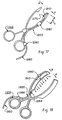
- Forceps 107 is generally comprised of light distributors 860 and light emitters 810.
- Each light distributor 860 includes a pair of arms 870 and a pair of connecting members 862. Connecting members 862 connect to a mating connecting members 896 of light source cables 894. Cables 894 connect to a light source (not shown).
- Light emitters 810 forms the gripping surfaces of arms 870, and provide focused or diffuse light. It should be appreciated that light emitters 810 may provide light for inspection, as well as transillumination. In the case of inspection the light is used to inspect a work area before proceeding with a further operation. With regard to transillumination, the light may be use to examine a bodily structure. For instance, a vein may be transilluminated to identify a blood clot before clamping and cutting.
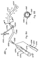
- Figs. 13 and 14 show a multi-purpose lighting device 108.
- Device 108 is generally comprised of a light delivery portion 902 and a handle portion 970.
- Light delivery portion 902 includes a light distributor 960 and a light emitter 910A.
- Handle portion 970 includes a central housing 972, a connecting member 974 and an endcap 976.
- handle portion 970 houses a power source 950 (e.g., batteries), a light source 952 (e.g., light bulb), a reflector 954, a light filter 956 and a switch means 974.
- Reflector 954 reflects the light generated by light source 952.
- Light filter 956 filters the reflected light before it exits through the open end of connecting member 974.
- Light source 952 is turned on and off by switch means 978.
- endcap 976 may include a contact member for completing a circuit for powering light source 952.
- connecting member 974 is dimensioned to receive a light distributor 960, as best seen in Fig. 14.
- light delivery portion 902 may include a light emitter 910A in the form of an illuminated ball (Fig. 13). The surface of the ball may be covered with cotton to form an illuminated cotton swab.
- light delivery portion 970 may include a light emitter 901B in the form of an end light (Fig. 14), a light emitter 910C in the form of an illuminated tongue depressor (Fig. 14), and a light emitter 910D in the form of a transillumination tray (Fig. 14), similar to tray 104, described above.
- device 108 serves a wide range of functions.
- the light delivery portions shown in Fig. 13 and 14 are shown solely for the purpose of illustration. In this respect, other types of light delivery portions, serving functions similar to those of the illustrated embodiments, are also contemplated.
- the portable light source housed in the handle portion may be suitably replaced by a remote light source (e.g., see Fig. 4A), with a light pipe for conveying the light therefrom.
- Lighting device 109 which functions as a flexible and formable "trouble light.”
- Lighting device 109 is generally comprised of a light delivery portion 1002 and a handle portion 1070.
- Light delivery portion 1002 includes a light distributor 1060 and a light emitter 1010.
- Light distributor 1060 includes a connecting member 1062 for connecting light distributor 1060 to handle portion 1070. It should be noted that in a preferred embodiment, light distributor 1060 is flexible.
- light distributor 1060 is comprised of a light pipe member 1063, a translucent or colored outer sheath 1061 and a formable wire 1065.
- Formable wire 1065 allows light distributor 1060 to be bent or positioned in a suitable manner.
- Light emitter 1010 is detachable from light distributor 1060 to provide a variety of multi-purpose light emitters. In the embodiment shown in Fig. 15A, light emitter 1010 takes the form of a glowing tip, which is rotatable to alter the focus, size or light intensity of lighted area 1004.
- Handle portion 1070 is similar to handle portion 970, described above.
- handle portion 1070 includes a central housing 1072, connecting member 1074, endcap 1076, and a switch means 1078.
- Handle portion 1070 houses a light source and a power source. It should be appreciated that handle portion 1070 is suitably replaced by a light pipe 1090 of conventional light source.
- Light pipe 1090 includes a cable 1094 and a mating connecting member 1096, which mates with connecting member 1062.
- Device 109 may optionally include a rigid support member 1050 to keep light distributor 1060 from changing positions.
- Support member 1050 includes an arm 1052 and clamp 1054. Clamp 1054 engages with light distributor 1060.
- Lighting device 1101 is generally comprised of a light distributor 1160 and light emitters 1110.
- Light distributor 1160 includes a connecting member 1162 for connecting light distributor 1160 to a light source (not shown). It should be noted that in a preferred embodiment, light distributor 1160 is formed of a flexible optic light guide.
- a protective outer sleeve 1170 covers light distributor 1160. Outer sleeve 1170 is preferably formed of a translucent or transparent material.
- An optional formable wire 1150 extends between light distributor 1160 and outer sleeve 1170, to permit lighting device 1101 to hold its shape once bent to a suitable position.
- Light emitters 1110 provide diffuse light D along length L, in addition to a focused beam of light B at the free end of lighting device 1101. It should be noted that at optional lens may be provided at the free end of lighting device 1101 to focus light B from light emitters 1110 in a desired pattern.
- Light delivery system 1200 is generally comprised of a light distributor 1260 and a light emitter 1210.
- Light distributor 1260 includes connecting members (not shown) for connecting light delivery system 1200 to a light source (not shown).
- Light distributor 1260 preferably takes the form of an optic light guide cable, which may be either rigid or flexible.
- Attachment members 1280 connect light distributor 1260 to forceps 1102. In a preferred embodiment attachment members take the form of clips.
- An opening 1270 is formed at the tip end of one arm of forceps 1102. Opening 1270 is dimensioned to receive light emitter 1210.
- Light emitter 1210 provide light along length L. It should be appreciated that a second opening 1270 may be formed in the second arm of forceps 1102, in order to receive a second light emitter.
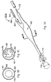
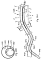
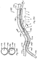
- Light delivery system 1300 is generally comprised of a light distributor 1360 and a light emitter 1310.
- Light, distributor 1360 includes connecting members (not shown) for connecting light delivery system 1300 to a light source (not shown).
- Light distributor 1360 preferably takes the form of an optic light guide cable, which may be either rigid or flexible.
- a connector 1364 is provided to connect and interface light distributor 1360 with light emitter 1310.
- Attachment members 1380 and 1388 connect light delivery system 1300 to forceps 1103.
- attachment member 1380 takes the form of a clip.
- Light emitter 1310 extends along the inner surface of the retractor arms.
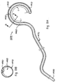
- Figs. 19A and 19B illustrate a spring-formed "rope" lighting device 1104.
- lighting device 1104 is generally comprised of a light distributor 1460 and a light emitter 1410.
- Light distributor 1460 interfaces with a self-contained miniature light source unit 1490.
- Light source unit 1490 includes a light source (e.g., LED, incandescent light, laser diodes or the like) and a power source (e.g., a button battery cell or the like).
- the miniaturization and portability of light source unit 1490 allows lighting device 1104 to be arrangeable within a bodily structure, such as abody cavity.
- a remote light source may substitute for self-contained light source unit 1490.
- light distributor 1460 is formed of a flexible optic light guide.
- a protective outer sleeve 1470 covers light distributor 1460.
- Outer sleeve 1470 is preferably formed of a translucent or transparent material.
- a spring 1450 extends between light distributor 1460 and outer sleeve 1470.
- Spring 1450 may be formed of a material which allows it to return to its original shape after being compressed. Accordingly, spring 1450 has a "memory,” which allows for advantageous use of lighting device 1104, as will be described below.
- Light emitter 1410 provides diffuse light D along length L.
- lighting device 1104 is shown with a generally round cross-sectional area, lighting device 1104 may have a cross-sectional area of other shapes, including a square and octagon.
- Lighting device 1104 finds particularly advantageous use as a means for holding a cavity open during a surgical procedure.
- lighting device 1104 is compressed (i.e., squeezed) and inserted through an opening into a cavity (e.g., a heart chamber).
- a cavity e.g., a heart chamber.
- spring 1450 may be suitably shaped to fit a particular application.
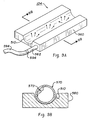
- Figs. 20A and 20B illustrates a smoke evacuation tube 1105 having an integrated light delivery system 1500.
- Light delivery system 1500 is generally comprised of a light distributor 1560 and light emitters 1510.
- Light distributor 1560 includes a connecting member 1562 for connecting light distributor 1560 to a light source (not shown).
- Light distributor 1560 is preferably formed of a flexible optic light guide.
- a protective outer sleeve 1574 covers light distributor 1560.
- Outer sleeve 1574 is preferably formed of a translucent or transparent material.
- An optional formable wire 1550 extends between light distributor 1560 and outer sleeve 1574, to allow smoke evacuation tube 1105 to hold its shape once arranged in a desired position.
- Light emitters 1510 provide diffuse light D along length L, in addition to a beam of light B. It should be noted that an optional lens may be provided at the free end of smoke evacuation tube 1105 to focus light B from light emitter 1510 in a desired pattern.
- a hollow tube 1570 forms an evacuation chamber 1572 for removing smoke. As best seen in Fig. 20B, hollow tube 1570 surrounds and connects to outer sleeve 1574. Hollow tube 1570 is preferably formed of a translucent or transparent material. It should be appreciated that in an alternative embodiment, sleeve 1574 and tube 1570 are suitably arranged adjacent to each other.
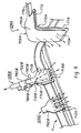
- Figs. 21A and 21B illustrates a suction tube 1106 having an integrated light delivery system 1600.
- Light delivery system 1600 is generally comprised of a light distributor 1660 and light emitters 1610.
- Light distributor 1660 includes a connecting member 1662 for connecting light distributor 1660 to a light source (not shown).
- Light distributor 1660 is preferably formed of a flexible optic light guide.
- a protective outer sleeve 1674 covers light distributor 1660.
- Outer sleeve 1674 is preferably formed of a translucent or transparent material.
- An optional formable wire 1650 extends between light distributor 1660 and outer sleeve 1674, to permit suction tube 1106 to hold its shape once arranged in a desired position.
- Light emitters 1610 provide diffuse light D along length L, in addition to a focused beam of light B. It should be noted that an optional lens may be provided at the free end of suction tube 1106 to focus light B from light emitter 1610 in a desired pattern.
- a hollow tube 1670 forms a suction chamber 1672 for suctioning smoke and other materials.
- a nozzle 1676 is formed at the free end of hollow tube 1670. As best seen in Fig. 21B, hollow tube 1670 is arranged adjacent and connected to outer sleeve 1674. Hollow tube 1670 is preferably formed of a translucent or transparent material.
- Figs. 22A and 22B illustrates a suction tube 1107 having an attachable light delivery system 1700.
- Light delivery system 1700 is generally comprised of a light distributor 1760 and light emitters 1710.
- Light distributor 1760 includes a connecting member 1762 for connecting light distributor 1660 to a light source (not shown).
- Light distributor 1760 is preferably formed of a flexible optic light guide.
- a protective outer sleeve 1774 covers light distributor 1760.
- Outer sleeve 1774 is preferably formed of a translucent or transparent material.
- An optional formable wire 1750 extends between light distributor 1760 and outer sleeve 1774, to permit suction tube 1107 to hold its shape once arranged in a desired position.
- Light emitters 1710 provide diffuse light D along length L, in addition to a beam of light B. It should be noted that an optional lens may be provided at the free end of suction tube 1107 to focus light B from light emitter 1710 in a desired pattern.
- a hollow tube 1770 forms a suction chamber 1772 for suctioning smoke and other materials.
- a nozzle 1776 is formed at the free end of hollow tube 1670.
- Hollow tube 1770 is preferably formed of a translucent or transparent material.
- Attachment members 1780 connect hollow tube 1770 to outer sleeve 1774.
- attachment member 1780 takes the form of a clip having a pair of gripping members respectively dimensioned to receive hollow tube 1770 and sleeve 1774 (Fig. 22A).
- attachment member 1780 may take other suitable forms.
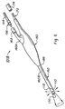
- Lighting device 1108 is generally comprised of a light distributor 1860 and light emitters 1810.
- Light distributor 1860 includes a connecting member 1862 for connecting light distributor 1860 to a light source (not shown). It should be noted that in a preferred embodiment of the present invention, light distributor 1860 is formed of a flexible optic light guide.
- a protective outer sleeve 1870 covers light distributor 1860. Outer sleeve 1870 is preferably formed of a translucent or transparent material.
- a custom-formed spring temper wire 1850 extends between light distributor 1860 and outer sleeve 1870.
- Wire 1850 may be compressed and will return to its original shape.
- Light emitter 1810 provides light along length L.
- a fastener 1880 is provided to hold lighting device 1108 in a desired shape.
- Fastener 1880 may take many suitable forms, including a mechanical fastener or adhesive (e.g., glue).
- a secondary wire 1852 is provided along a portion of light distributor 1860. Wire 1852 may be malleable or spring temper.
- Tabs 1882 hold lighting device 1108 in a desired location, and can also be used to retract tissue during a surgical procedure. In a preferred embodiment, tabs 1882 take the form of adhesive tape.
- the present invention as illustrated by the embodiments of Figures 11 and 18 allows for significant improvements to surgical procedures.
- the light delivery system attaches to a surgical instrument or forms an integral part of the structure of a surgical instrument. Accordingly, the present invention eliminates the need for a lighting device mounted elsewhere in an operating room, or a hand held lighting device.
- the light emitter of the present invention provides light in a suitable direction, and with varying intensity levels. As a result, the medical personnel receive an excellent view of the work area.
Landscapes
- Physics & Mathematics (AREA)
- General Physics & Mathematics (AREA)
- Optics & Photonics (AREA)
- Health & Medical Sciences (AREA)
- Life Sciences & Earth Sciences (AREA)
- Surgery (AREA)
- Biomedical Technology (AREA)
- Engineering & Computer Science (AREA)
- Nuclear Medicine, Radiotherapy & Molecular Imaging (AREA)
- Heart & Thoracic Surgery (AREA)
- Medical Informatics (AREA)
- Molecular Biology (AREA)
- Animal Behavior & Ethology (AREA)
- General Health & Medical Sciences (AREA)
- Public Health (AREA)
- Veterinary Medicine (AREA)
- Surgical Instruments (AREA)
Claims (13)
- Instrument (1103, 106 A bis C) zum Unterstützen einer chirurgischen Operation mit einem Handgriff und einem Retraktorarm, dessen eines Ende mit dem Handgriff verbunden ist und dessen anderes Ende von dem anderen Ende entfernt ist, gekennzeichnet durch einen länglichen Lichtemitter (1310, 710 A-C), der sich entlang der Länge des Retraktorarms erstreckt, und einen Verbinder (1364) zum Verbinden des Lichtemitters (1310, 710 A-C) mit einem Lichtverteiler (1360), welcher Lichtemitter (1310, 710 A-C) Lichtextraktionsgebilde (22, 28, 30, 32) entlang zumindest eines Teils der Länge des Lichtemitters aufweist.
- Instrument nach Anspruch 1, weiterhin dadurch gekennzeichnet, dass der Lichtemitter (1310, 710 A-C) im wesentlichen transparent ist.
- Instrument nach Anspruch 1 oder Anspruch 2, weiterhin dadurch gekennzeichnet, dass der Lichtemitter (1310, 710 A) unter einem Winkel mit Bezug auf den Handgriff orientiert ist.
- Instrument nach einem der vorhergehenden Ansprüche, weiterhin dadurch gekennzeichnet, dass der Retraktorarm unter einem Winkel mit Bezug auf den Handgriff orientiert ist.
- Instrument nach einem der vorhergehenden Ansprüche, weiterhin dadurch gekennzeichnet, dass die Lichtextraktionsgebilde ein gedrucktes Muster (22) auf einer Oberfläche (20) des Lichtemitters (1310, 710 A-C) aufweisen.
- Instrument nach einem der vorhergehenden Ansprüche, weiterhin gekennzeichnet durch Befestigungsmittel (1380, 780B) zum Befestigen des Lichtemitters (1310, 710B) an dem Retraktorarm in der Weise, dass der Lichtemitter (1310, 710B) und der Retraktorarm im wesentlichen parallel sind.
- Instrument nach Anspruch 6, weiterhin dadurch gekennzeichnet, dass die Befestigungsmittel (1380) Klemmen aufweisen.
- Instrument nach einem der vorhergehenden Ansprüche, weiterhin dadurch gekennzeichnet, dass der Retraktorarm einen im allgemeinen gekrümmten Querschnitt enthält.
- Instrument nach einem der vorhergehenden Ansprüche, weiterhin dadurch gekennzeichnet, dass der Lichtverteiler (1360) ein optisches Lichtleiterkabel aufweist.
- Instrument nach Anspruch 9, weiterhin dadurch gekennzeichnet, dass das Kabel (1360) starr ist.
- Instrument nach Anspruch 9, weiterhin dadurch gekennzeichnet, dass das Kabel (1360) flexibel ist.
- Instrument nach einem der vorhergehenden Ansprüche, weiterhin gekennzeichnet durch Klemmen (1380) zum Befestigen des Lichtemitters (1310) an dem Retraktorarm.
- Instrument nach einem der vorhergehenden Ansprüche, weiterhin dadurch gekennzeichnet, dass die Lichtextraktionsgebilde (22, 28, 30, 32) entlang im wesentlichen der gesamten Länge des Lichtemitters (1310, 710 A-C) angeordnet sind.
Applications Claiming Priority (3)
| Application Number | Priority Date | Filing Date | Title |
|---|---|---|---|
| US886666 | 1997-07-02 | ||
| US08/886,666 US20020058931A1 (en) | 1995-06-27 | 1997-07-02 | Light delivery system and applications thereof |
| PCT/US1998/013628 WO1999001696A1 (en) | 1997-07-02 | 1998-07-02 | Light delivery system and applications thereof |
Publications (2)
| Publication Number | Publication Date |
|---|---|
| EP0993579A1 EP0993579A1 (de) | 2000-04-19 |
| EP0993579B1 true EP0993579B1 (de) | 2007-09-05 |
Family
ID=25389492
Family Applications (1)
| Application Number | Title | Priority Date | Filing Date |
|---|---|---|---|
| EP98933012A Expired - Lifetime EP0993579B1 (de) | 1997-07-02 | 1998-07-02 | Beleuchtungssystem und dessen anwendung |
Country Status (6)
| Country | Link |
|---|---|
| US (1) | US20020058931A1 (de) |
| EP (1) | EP0993579B1 (de) |
| JP (1) | JP2002514127A (de) |
| AU (1) | AU8277798A (de) |
| DE (1) | DE69838386T2 (de) |
| WO (1) | WO1999001696A1 (de) |
Cited By (1)
| Publication number | Priority date | Publication date | Assignee | Title |
|---|---|---|---|---|
| EP3031401A1 (de) | 2014-12-12 | 2016-06-15 | Marco Piciche' | Beleuchtendes medizinisches instrument |
Families Citing this family (74)
| Publication number | Priority date | Publication date | Assignee | Title |
|---|---|---|---|---|
| US9167959B1 (en) * | 2010-03-26 | 2015-10-27 | Optech Ventures, Llc | Illumination for enhanced contrast in debridement apparatus and method |
| US6814700B1 (en) | 1996-03-04 | 2004-11-09 | Heartport, Inc. | Soft tissue retractor and method for providing surgical access |
| US7306559B2 (en) * | 1997-07-02 | 2007-12-11 | Lumitex, Inc. | Illuminated surgical retractor |
| US6739744B2 (en) | 1997-07-02 | 2004-05-25 | Lumitex, Inc. | Light delivery systems and applications thereof |
| US6591049B2 (en) | 1997-07-02 | 2003-07-08 | Lumitex, Inc. | Light delivery systems and applications thereof |
| US6228025B1 (en) | 1998-05-01 | 2001-05-08 | Genzyme Corporation | Illuminated saphenous vein retractor |
| US6585727B1 (en) | 1999-10-22 | 2003-07-01 | Genzyme Corporation | Surgical instrument light source and surgical illumination method |
| US6322499B1 (en) | 2000-01-20 | 2001-11-27 | Genzyme Corporation | Pivotal and illuminated saphenous vein retractor |
| US6497654B1 (en) | 2000-02-18 | 2002-12-24 | Genzyme Corporation | Illuminated rectal retractor |
| US6428473B1 (en) | 2000-02-18 | 2002-08-06 | Genzyme Corporation | Illuminated rectal retractor |
| US20060009763A1 (en) * | 2000-02-22 | 2006-01-12 | Rhytech Limited | Tissue treatment system |
| CA2414312A1 (en) * | 2000-07-20 | 2002-01-31 | Tom Jacobs | Fiberoptic lighting accessory |
| US6554768B1 (en) | 2000-09-05 | 2003-04-29 | Genzyme Corporation | Illuminated deep pelvic retractor |
| MXPA03011558A (es) * | 2001-06-12 | 2004-03-26 | Wellstat Therapeutics Corp | Compuestos para el tratamiento de desordenes metabolicos. |
| US7290915B2 (en) | 2001-07-20 | 2007-11-06 | Solovay Kenneth S | Light coupling assembly |
| US6817978B2 (en) | 2002-01-23 | 2004-11-16 | Teleflex-Ct Devices Incorporated | Illuminated retractor for use in connection with harvesting a blood vessel from the arm |
| US6805666B2 (en) | 2002-05-23 | 2004-10-19 | Donna D. Holland | Pivotal and illuminated saphenous vein retractor with tapered design |
| JP4028448B2 (ja) * | 2003-07-14 | 2007-12-26 | 株式会社東海理化電機製作所 | ライトガイド及びそれを用いた照光式スイッチ装置 |
| US7357526B2 (en) | 2003-08-22 | 2008-04-15 | Milwaukee Electric Tool Corporation | Power tool and accessory |
| JP4452607B2 (ja) | 2004-03-05 | 2010-04-21 | 順一 島田 | 照明装置、フィルタ装置、画像表示装置 |
| GB2422314A (en) * | 2005-01-25 | 2006-07-26 | William Lee Sanderson | Self-contained, illuminated single use surgical retractor |
| US7355800B2 (en) * | 2005-02-07 | 2008-04-08 | Coherent, Inc. | Apparatus for projecting a line of light from a diode-laser array |
| US20070205969A1 (en) | 2005-02-23 | 2007-09-06 | Pixtronix, Incorporated | Direct-view MEMS display devices and methods for generating images thereon |
| US9082353B2 (en) | 2010-01-05 | 2015-07-14 | Pixtronix, Inc. | Circuits for controlling display apparatus |
| US9261694B2 (en) | 2005-02-23 | 2016-02-16 | Pixtronix, Inc. | Display apparatus and methods for manufacture thereof |
| US7999994B2 (en) | 2005-02-23 | 2011-08-16 | Pixtronix, Inc. | Display apparatus and methods for manufacture thereof |
| US8519945B2 (en) | 2006-01-06 | 2013-08-27 | Pixtronix, Inc. | Circuits for controlling display apparatus |
| US9229222B2 (en) | 2005-02-23 | 2016-01-05 | Pixtronix, Inc. | Alignment methods in fluid-filled MEMS displays |
| US8310442B2 (en) | 2005-02-23 | 2012-11-13 | Pixtronix, Inc. | Circuits for controlling display apparatus |
| US9158106B2 (en) | 2005-02-23 | 2015-10-13 | Pixtronix, Inc. | Display methods and apparatus |
| US20060229689A1 (en) * | 2005-04-08 | 2006-10-12 | Led Technologies, Llc | LED therapy device |
| US8684577B2 (en) * | 2005-05-13 | 2014-04-01 | Invuity, Inc. | Body cavity illumination system |
| US20070060795A1 (en) * | 2005-09-14 | 2007-03-15 | Spotlight Surgical, Inc. | Lighted surgical retractors with LED illumination light engines |
| US7874982B2 (en) * | 2005-11-02 | 2011-01-25 | Depuy Spine, Inc. | Illuminated surgical access system including a surgical access device and coupled light emitter |
| US8526096B2 (en) | 2006-02-23 | 2013-09-03 | Pixtronix, Inc. | Mechanical light modulators with stressed beams |
| FR2900220B1 (fr) * | 2006-04-24 | 2008-07-18 | Valeo Vision Sa | Dispositif d'eclairage ou de signalisation avec effet de profondeur. |
| GB0608315D0 (en) * | 2006-04-27 | 2006-06-07 | Univ St Andrews | Light emitting device for use in therapeutic and/or cosmetic treatment |
| US9176318B2 (en) | 2007-05-18 | 2015-11-03 | Pixtronix, Inc. | Methods for manufacturing fluid-filled MEMS displays |
| PT103654B (pt) * | 2007-02-07 | 2009-04-30 | Fernando Antonio Cepeda Costa | Aparelho iluminador para instrumentos cirúrgicos |
| US8506565B2 (en) * | 2007-08-23 | 2013-08-13 | Covidien Lp | Electrosurgical device with LED adapter |
| GB0800835D0 (en) | 2008-01-17 | 2008-02-27 | Cardioprec Ltd | Retractor |
| US8248560B2 (en) | 2008-04-18 | 2012-08-21 | Pixtronix, Inc. | Light guides and backlight systems incorporating prismatic structures and light redirectors |
| JP5308741B2 (ja) * | 2008-08-25 | 2013-10-09 | オリンパスメディカルシステムズ株式会社 | 医療機器 |
| US8169679B2 (en) | 2008-10-27 | 2012-05-01 | Pixtronix, Inc. | MEMS anchors |
| US20110190749A1 (en) * | 2008-11-24 | 2011-08-04 | Mcmillan Kathleen | Low Profile Apparatus and Method for Phototherapy |
| JP2012509720A (ja) * | 2008-11-24 | 2012-04-26 | グラディアント リサーチ,エルエルシー | 軟組織の光熱治療 |
| WO2010102099A1 (en) * | 2009-03-04 | 2010-09-10 | Gradiant Research, Llc | Method and apparatus for cancer therapy |
| KR101096401B1 (ko) * | 2009-04-27 | 2011-12-21 | 국립암센터 | 수술 기구 |
| US20100312241A1 (en) * | 2009-06-09 | 2010-12-09 | Erickson Jr Jerry Martin | Implementation of light sources with electocautery units |
| US8480279B2 (en) * | 2009-11-11 | 2013-07-09 | Alcon Research, Ltd. | Structured illumination probe and method |
| US20110143304A1 (en) * | 2009-12-11 | 2011-06-16 | Hu-Friedy Mfg. Co., Inc. | Adaptor for Lighted Dental Device |
| US8496475B2 (en) * | 2009-12-11 | 2013-07-30 | Hu-Friedy Mfg. Co., LLC. | Integrated, lighted ultrasonic inserts |
| WO2011097258A1 (en) | 2010-02-02 | 2011-08-11 | Pixtronix, Inc. | Circuits for controlling display apparatus |
| JP2013519121A (ja) | 2010-02-02 | 2013-05-23 | ピクストロニックス・インコーポレーテッド | 低温封孔流体充填ディスプレイ装置を製造するための方法 |
| GB201015746D0 (en) | 2010-09-21 | 2010-10-27 | Cardioprec Ltd | Optical switch |
| EP2624777B1 (de) | 2010-10-07 | 2019-03-20 | Gradiant Research, Llc | Vorrichtung für eine hautkrebs-wärmetherapie |
| US20120101343A1 (en) * | 2010-10-21 | 2012-04-26 | Duffy Thomas P | Medical imaging device |
| JP2013169276A (ja) * | 2012-02-20 | 2013-09-02 | Fujifilm Corp | 硬性内視鏡装置の連結固定具及び硬性内視鏡装置 |
| CA2883231C (en) | 2012-08-28 | 2022-12-06 | Instruventional Inc. | Adjustable electrosurgical pencil |
| US9134552B2 (en) | 2013-03-13 | 2015-09-15 | Pixtronix, Inc. | Display apparatus with narrow gap electrostatic actuators |
| US9808231B2 (en) | 2013-07-09 | 2017-11-07 | Edwards Lifesciences Corporation | Tissue retractor |
| CA2827695C (en) | 2013-09-20 | 2021-02-16 | Leonard Ineson | Adjustable electrosurgical pencil |
| JP6730765B2 (ja) * | 2014-01-28 | 2020-07-29 | インブイティ・インコーポレイテッド | ドロップイン外科手術用照明器 |
| US20150272584A1 (en) * | 2014-03-31 | 2015-10-01 | Coloplast A/S | Adapter attachable to a shaft of an anchor delivery tool |
| US10716587B2 (en) | 2014-06-13 | 2020-07-21 | Surgis Medical Llc | Surgical device with light |
| EP3679864B1 (de) * | 2014-09-13 | 2022-11-09 | Yusuke Shimizu | Medizinischer retraktor |
| KR102475202B1 (ko) * | 2014-12-08 | 2022-12-07 | 인뷰이티 인코퍼레이티드 | 전기수술 조명 및 감지를 위한 방법 및 장치 |
| US20160327721A1 (en) * | 2015-05-04 | 2016-11-10 | Corning Incorporated | Optical fiber lighting device and method |
| US10433960B1 (en) | 2015-05-07 | 2019-10-08 | Cardioprecision Limited | Method and system for transcatheter intervention |
| WO2017183033A1 (en) * | 2016-04-19 | 2017-10-26 | Asymmetric Medical Ltd. | Fiberoptic for medical applications |
| WO2017208596A1 (ja) * | 2016-05-31 | 2017-12-07 | コニカミノルタ株式会社 | 外科用手術器具 |
| US11547463B2 (en) | 2018-09-21 | 2023-01-10 | Covidien Lp | Smoke evacuation electrosurgical pencil with adjustable electrode and vent tube |
| CN113056238A (zh) * | 2018-10-17 | 2021-06-29 | 帕蒂医药有限公司 | 用于将照明装置附接至手持式的电外科器械的适配器组件 |
| US11596466B2 (en) | 2019-09-09 | 2023-03-07 | Covidien Lp | Surgical instrument with evacuation port and method |
Family Cites Families (7)
| Publication number | Priority date | Publication date | Assignee | Title |
|---|---|---|---|---|
| DE8600868U1 (de) * | 1986-01-16 | 1986-03-06 | Dausch, Hermann, 78532 Tuttlingen | Mikrochirurgische Zange |
| DE8607483U1 (de) * | 1986-03-15 | 1986-06-12 | Effner und Spreine GmbH, 1000 Berlin | Chirurgisches Spreizinstrument |
| US5005108A (en) * | 1989-02-10 | 1991-04-02 | Lumitex, Inc. | Thin panel illuminator |
| US5281134A (en) * | 1991-11-19 | 1994-01-25 | Schultz Allen J | Fiber optic illumination system for dental instruments |
| DE4234050A1 (de) * | 1992-10-09 | 1993-06-17 | Rudolf Dr Med Drumm | Lichtquelle direkt am punkt der untersuchung, bearbeitung und operation |
| US5709459A (en) * | 1993-10-08 | 1998-01-20 | Cogent Light Technologies, Inc. | Surgical luminaire |
| US5667291A (en) * | 1995-05-23 | 1997-09-16 | Surgical Acuity, Inc. | Illumination assembly for dental and medical applications |
-
1997
- 1997-07-02 US US08/886,666 patent/US20020058931A1/en not_active Abandoned
-
1998
- 1998-07-02 EP EP98933012A patent/EP0993579B1/de not_active Expired - Lifetime
- 1998-07-02 WO PCT/US1998/013628 patent/WO1999001696A1/en active IP Right Grant
- 1998-07-02 AU AU82777/98A patent/AU8277798A/en not_active Abandoned
- 1998-07-02 JP JP50873499A patent/JP2002514127A/ja active Pending
- 1998-07-02 DE DE69838386T patent/DE69838386T2/de not_active Expired - Lifetime
Cited By (1)
| Publication number | Priority date | Publication date | Assignee | Title |
|---|---|---|---|---|
| EP3031401A1 (de) | 2014-12-12 | 2016-06-15 | Marco Piciche' | Beleuchtendes medizinisches instrument |
Also Published As
| Publication number | Publication date |
|---|---|
| AU8277798A (en) | 1999-01-25 |
| DE69838386T2 (de) | 2008-05-29 |
| DE69838386D1 (de) | 2007-10-18 |
| US20020058931A1 (en) | 2002-05-16 |
| EP0993579A1 (de) | 2000-04-19 |
| WO1999001696A1 (en) | 1999-01-14 |
| JP2002514127A (ja) | 2002-05-14 |
Similar Documents
| Publication | Publication Date | Title |
|---|---|---|
| EP0993579B1 (de) | Beleuchtungssystem und dessen anwendung | |
| EP1561137B1 (de) | Beleuchtetes chirurgisches rektaktionsglied | |
| EP1278007B1 (de) | Beleuchtungssystem und dessen Anwendung | |
| US6504985B2 (en) | Illuminated surgical retractor | |
| US6739744B2 (en) | Light delivery systems and applications thereof | |
| US20050171408A1 (en) | Light delivery systems and applications thereof | |
| US9220401B2 (en) | Film illumination system | |
| US7063436B2 (en) | Light source for ophthalmic use | |
| EP1978861B1 (de) | Retraktorbeleuchtungssystem | |
| EP2320967B1 (de) | Medizinische instrumente aus cycloolefinpolymer und cycloolefincopolymer | |
| EP2246000B1 (de) | Chirurgisches Instrument | |
| GB2505463A (en) | Transparent retractor with light |
Legal Events
| Date | Code | Title | Description |
|---|---|---|---|
| PUAI | Public reference made under article 153(3) epc to a published international application that has entered the european phase |
Free format text: ORIGINAL CODE: 0009012 |
|
| 17P | Request for examination filed |
Effective date: 19991220 |
|
| AK | Designated contracting states |
Kind code of ref document: A1 Designated state(s): DE FR GB |
|
| 17Q | First examination report despatched |
Effective date: 20010813 |
|
| GRAP | Despatch of communication of intention to grant a patent |
Free format text: ORIGINAL CODE: EPIDOSNIGR1 |
|
| GRAS | Grant fee paid |
Free format text: ORIGINAL CODE: EPIDOSNIGR3 |
|
| GRAA | (expected) grant |
Free format text: ORIGINAL CODE: 0009210 |
|
| AK | Designated contracting states |
Kind code of ref document: B1 Designated state(s): DE FR GB |
|
| REG | Reference to a national code |
Ref country code: GB Ref legal event code: FG4D |
|
| REF | Corresponds to: |
Ref document number: 69838386 Country of ref document: DE Date of ref document: 20071018 Kind code of ref document: P |
|
| ET | Fr: translation filed | ||
| PLBE | No opposition filed within time limit |
Free format text: ORIGINAL CODE: 0009261 |
|
| STAA | Information on the status of an ep patent application or granted ep patent |
Free format text: STATUS: NO OPPOSITION FILED WITHIN TIME LIMIT |
|
| 26N | No opposition filed |
Effective date: 20080606 |
|
| REG | Reference to a national code |
Ref country code: FR Ref legal event code: PLFP Year of fee payment: 19 |
|
| REG | Reference to a national code |
Ref country code: FR Ref legal event code: PLFP Year of fee payment: 20 |
|
| PGFP | Annual fee paid to national office [announced via postgrant information from national office to epo] |
Ref country code: FR Payment date: 20170728 Year of fee payment: 20 Ref country code: GB Payment date: 20170728 Year of fee payment: 20 Ref country code: DE Payment date: 20170731 Year of fee payment: 20 |
|
| REG | Reference to a national code |
Ref country code: DE Ref legal event code: R071 Ref document number: 69838386 Country of ref document: DE |
|
| REG | Reference to a national code |
Ref country code: GB Ref legal event code: PE20 Expiry date: 20180701 |
|
| PG25 | Lapsed in a contracting state [announced via postgrant information from national office to epo] |
Ref country code: GB Free format text: LAPSE BECAUSE OF EXPIRATION OF PROTECTION Effective date: 20180701 |