EP0992647A2 - Adjustable hinge for door frames - Google Patents
Adjustable hinge for door frames Download PDFInfo
- Publication number
- EP0992647A2 EP0992647A2 EP99830625A EP99830625A EP0992647A2 EP 0992647 A2 EP0992647 A2 EP 0992647A2 EP 99830625 A EP99830625 A EP 99830625A EP 99830625 A EP99830625 A EP 99830625A EP 0992647 A2 EP0992647 A2 EP 0992647A2
- Authority
- EP
- European Patent Office
- Prior art keywords
- bushing
- hinge
- screw
- pin
- hinge according
- Prior art date
- Legal status (The legal status is an assumption and is not a legal conclusion. Google has not performed a legal analysis and makes no representation as to the accuracy of the status listed.)
- Granted
Links
- 238000003780 insertion Methods 0.000 claims description 6
- 230000037431 insertion Effects 0.000 claims description 6
- 239000003381 stabilizer Substances 0.000 claims description 5
- 238000009877 rendering Methods 0.000 claims description 2
- 230000000284 resting effect Effects 0.000 claims description 2
- 238000000034 method Methods 0.000 description 3
- 125000006850 spacer group Chemical group 0.000 description 3
- 229910000831 Steel Inorganic materials 0.000 description 1
- 239000004411 aluminium Substances 0.000 description 1
- 229910052782 aluminium Inorganic materials 0.000 description 1
- XAGFODPZIPBFFR-UHFFFAOYSA-N aluminium Chemical compound [Al] XAGFODPZIPBFFR-UHFFFAOYSA-N 0.000 description 1
- 230000008030 elimination Effects 0.000 description 1
- 238000003379 elimination reaction Methods 0.000 description 1
- 229910001385 heavy metal Inorganic materials 0.000 description 1
- 238000004519 manufacturing process Methods 0.000 description 1
- 238000005259 measurement Methods 0.000 description 1
- 238000012986 modification Methods 0.000 description 1
- 230000004048 modification Effects 0.000 description 1
- 238000003825 pressing Methods 0.000 description 1
- 230000003019 stabilising effect Effects 0.000 description 1
- 239000010959 steel Substances 0.000 description 1
- 238000003860 storage Methods 0.000 description 1
Images


Classifications
-
- E—FIXED CONSTRUCTIONS
- E05—LOCKS; KEYS; WINDOW OR DOOR FITTINGS; SAFES
- E05D—HINGES OR SUSPENSION DEVICES FOR DOORS, WINDOWS OR WINGS
- E05D5/00—Construction of single parts, e.g. the parts for attachment
- E05D5/02—Parts for attachment, e.g. flaps
- E05D5/0215—Parts for attachment, e.g. flaps for attachment to profile members or the like
- E05D5/0223—Parts for attachment, e.g. flaps for attachment to profile members or the like with parts, e.g. screws, extending through the profile wall or engaging profile grooves
- E05D5/023—Parts for attachment, e.g. flaps for attachment to profile members or the like with parts, e.g. screws, extending through the profile wall or engaging profile grooves with parts extending through the profile wall
-
- E—FIXED CONSTRUCTIONS
- E05—LOCKS; KEYS; WINDOW OR DOOR FITTINGS; SAFES
- E05D—HINGES OR SUSPENSION DEVICES FOR DOORS, WINDOWS OR WINGS
- E05D11/00—Additional features or accessories of hinges
- E05D11/0054—Covers, e.g. for protection
-
- E—FIXED CONSTRUCTIONS
- E05—LOCKS; KEYS; WINDOW OR DOOR FITTINGS; SAFES
- E05D—HINGES OR SUSPENSION DEVICES FOR DOORS, WINDOWS OR WINGS
- E05D7/00—Hinges or pivots of special construction
- E05D7/0009—Adjustable hinges
- E05D7/0018—Adjustable hinges at the hinge axis
- E05D7/0045—Adjustable hinges at the hinge axis in a radial direction
- E05D2007/0081—Adjustable hinges at the hinge axis in a radial direction with swinging or rolling sleeves
-
- E—FIXED CONSTRUCTIONS
- E05—LOCKS; KEYS; WINDOW OR DOOR FITTINGS; SAFES
- E05D—HINGES OR SUSPENSION DEVICES FOR DOORS, WINDOWS OR WINGS
- E05D7/00—Hinges or pivots of special construction
- E05D7/04—Hinges adjustable relative to the wing or the frame
- E05D2007/0469—Hinges adjustable relative to the wing or the frame in an axial direction
-
- E—FIXED CONSTRUCTIONS
- E05—LOCKS; KEYS; WINDOW OR DOOR FITTINGS; SAFES
- E05D—HINGES OR SUSPENSION DEVICES FOR DOORS, WINDOWS OR WINGS
- E05D11/00—Additional features or accessories of hinges
- E05D11/0054—Covers, e.g. for protection
- E05D2011/0063—Covers, e.g. for protection for screw-heads or bolt-heads
-
- E—FIXED CONSTRUCTIONS
- E05—LOCKS; KEYS; WINDOW OR DOOR FITTINGS; SAFES
- E05D—HINGES OR SUSPENSION DEVICES FOR DOORS, WINDOWS OR WINGS
- E05D5/00—Construction of single parts, e.g. the parts for attachment
- E05D5/10—Pins, sockets or sleeves; Removable pins
- E05D5/14—Construction of sockets or sleeves
-
- E—FIXED CONSTRUCTIONS
- E05—LOCKS; KEYS; WINDOW OR DOOR FITTINGS; SAFES
- E05D—HINGES OR SUSPENSION DEVICES FOR DOORS, WINDOWS OR WINGS
- E05D7/00—Hinges or pivots of special construction
- E05D7/04—Hinges adjustable relative to the wing or the frame
- E05D7/0415—Hinges adjustable relative to the wing or the frame with adjusting drive means
- E05D7/0423—Screw-and-nut mechanisms
-
- E—FIXED CONSTRUCTIONS
- E05—LOCKS; KEYS; WINDOW OR DOOR FITTINGS; SAFES
- E05Y—INDEXING SCHEME ASSOCIATED WITH SUBCLASSES E05D AND E05F, RELATING TO CONSTRUCTION ELEMENTS, ELECTRIC CONTROL, POWER SUPPLY, POWER SIGNAL OR TRANSMISSION, USER INTERFACES, MOUNTING OR COUPLING, DETAILS, ACCESSORIES, AUXILIARY OPERATIONS NOT OTHERWISE PROVIDED FOR, APPLICATION THEREOF
- E05Y2900/00—Application of doors, windows, wings or fittings thereof
- E05Y2900/10—Application of doors, windows, wings or fittings thereof for buildings or parts thereof
- E05Y2900/13—Type of wing
- E05Y2900/132—Doors
Definitions
- the present invention relates to a hinge which is adjustable on three axes, for doorframes, in particular for heavy metal doorframes, that is to say, of the type which are large and, therefore, weigh more than standard interior models.
- the hinges used for the above-mentioned doorframes must satisfy special safety criteria and, therefore, differ from those used for normal (interior) doorframes. These differences are of a structural nature and consist of larger dimensions, partly necessary due to the greater weight of the doorframes, and the fact that they are fixed in place using screws which must be concealed by covering them with special anti-tampering covers. Moreover, due to the particular nature of the application, these hinges require adjustment to allow optimum adjustment of the position of the mobile frame relative to that of the fixed frame, given the reduced tolerance between them.
- Such hinges consist of two bodies, normally made of aluminium, which can be fixed to the mobile and fixed frames, and a steel hinge pin, which can be inserted in respective through-holes in the bodies inside a centring bushing (normally made of plastic and self-lubricating).
- the centre of the pin is fitted with a collar which is integral with the pin and whose diameter is greater than that of the through-holes in the bodies, to prevent the pin from exiting the seats in the bodies (see also patent IT - 1.221.237 by the Applicant).
- the bodies have brackets for fixing to the doorframe, through which there pass, in a direction perpendicular to the hinge pin, strong screws whose heads are housed in respective seats in the brackets.
- the latter outside the screw heads, have guides defining seats for strong covers which slide parallel with the hinge pin.
- the covers conceal the screw heads completely and define a surface which makes contact with the entire cylindrical part of the hinge, in which there is the hole for the bushing, and the free end of the bracket which starts from this cylindrical part and bears the cover guides.
- the above-mentioned bushings normally consist of a cylindrical element, closed at one end, and a collar located at the open end. They also have an axial hole, offset relative to the longitudinal axis of the cylindrical element, and a set of projections or teeth, normally located on the outside of the bushing and immediately below the collar for contact with the hinge body, equidistant and designed to engage with matching seats made in the holes in the hinge bodies.
- the shape of the bushings allows the axis of the hinge pins to be moved on a plane parallel with the doorframe, by rotation of the pins about their axes, thus adjusting the position of the mobile frame relative to the fixed frame. This adjustment is carried out by raising the wing with the relative removal of the teeth from the seats of one or both bushings on the hinge, adjusting them in the new position, and finally re-inserting the bushings in the hinge bodies, simultaneously lowering the wing into the new position.
- each bushing on the hinge consists of two separate elements, connected to one another by axial connecting means and free to rotate relative to one another.
- the first element is cylindrical and houses the portion of the pin, since it has a seat for holding the pin which is offset relative to a longitudinal axis of the bushing, whilst the other element defines a first collar whose diameter is greater than the diameter of the axial hole which houses the bushing.
- Adjustment means act upon the first element, being designed to vary its position relative to the second element by rotating the first element, with an action from outside the assembled and operating hinge body, between several stable conditions which are defined by grooves in the axial hole.
- both of the above-mentioned solutions allow adjustment of the position of the mobile frame in small steps, that is to say, according to the number of grooves on the circumference of the bushings and, respectively, in the seats of the hinge bodies, whilst the market for such products requires more precise adjustment of the doorframes, through a more continuous pin - bushing movement system able to obtain positioning which is more correct than the previous solutions.
- the hinge would preferably, for the purpose of structural completeness, allow adjustment of the height of the mobile frame relative to the fixed frame. This adjustment can be obtained through a solution known for some time now, using ring-shaped spacers, that is to say, washers, which may be inserted on the pin and have the same diameter as the pin collar, thus separating the two hinge bodies.
- the aim of the present invention is, therefore, to overcome the above-mentioned disadvantages by providing a hinge for doorframes which has a simple structure, is extremely precise and rapid in adjusting the doorframe through three movements, that is to say, on the three axes of the hinge.
- Another aim of the present invention is to provide a hinge which is extremely practical and safe when assembled on the mobile and fixed doorframes.
- the hinge disclosed may be used on "heavy" doorframes, such as exterior doors, main front doors, gates, etc.
- This hinge indicated as a whole by the numeral 1, comprises a first and a second body 2 and 3, which may be attached to a mobile frame IM and to a fixed frame IF (schematically illustrated in Figure 5, being of the known type and not part of the subject matter of the present invention) by means of brackets 4 and 5 which house screw means 100 for fixing to the doorframes (described in more detail below).
- the two bodies 2 and 3 are joined together by a pin 6 inserted, inside a first and a second lower and upper cylindrical bushing 7 and 8, in axial through-holes 9 and 10 in the first and second bodies 2 and 3, the holes extending along a longitudinal axis Z (which defines the vertical axis of the hinge).
- first means 11 for adjusting the position of the hinge pin 6, acting between the bushing and the hole 9, in such a way as to allow the position of the pin 6 relative to the longitudinal axis Z to move radially in both directions and on a plane P parallel with the doorframe.
- these first means 11 for adjusting the pin 6 envisage, at least as regards the hinge body 2 defined by the upper part of the hinge 1 when assembly is complete, means 35 for rendering the bushing 7 and the portion of the pin 6 housed in it integral, so that they define a single adjustable body.
- the bushing 7 has an outer radial projection 12 which can engage in a notch 13 in the inner surface of the hole 9 in the hinge body 2.
- the engagement of the projection 12 in the notch 13 defines a pivoting point F (see Figure 3), in the style of a cam, for the first bushing 7, allowing it to perform a pendular movement in both directions together with the portion of the pin 6 housed in it, thanks to relative means 14, which can be operated from the outside, acting between the pin 6 and the hole 9 in such a way as to allow the above-mentioned adjustment of the position of the pin 6.
- the second bushing 8 may also have adjustment means designed to allow the variation of the part of the pin 6 housed in it, in particular relative to an axis perpendicular to the plane P.
- Such means are of the known type (for example, the second bushing 8 is made with an eccentric hole) and are not, therefore, described here.
- the above-mentioned connecting means 35 consist of one or a pair of opposite (in the case of a pair) flat surface sections 36 on the portion of the pin 6. These flat sections 36 connect, in such a way that they can slide, inside the bushing 7 which, in turn, has one or a pair of flat surfaces 37, allowing relative locking between the pin 6 and bushing 7.
- a single body is formed, which is adjustable and consists of the portion of the pin 6 and the bushing 7, upon which the pendular movement means 14 can act.
- the latter are positioned so that they are substantially transversal to the radial projection 12 and the notch 13.
- the pendular movement means 14 consist of a screw 15 which passes crosswise through the first bushing 7, which has coaxial countersunk openings 16. These openings 16 have initial dimensions smaller than the diameter of the screw 15, so that they are deformed during assembly with the screw 15, resulting in a self-locking action between the screw 15 and the first bushing 7. Moreover, the screw 15 is connected, in such a way that it can be screwed in and out, to the pin 6 which has a threaded through-hole 17.
- the screw 15 is mounted on the bushing 7 and pin 6 before the latter are housed inside the hole 9, in such a way that the screw 15 is completely housed in the hole 9, with one of its ends in contact with an arched inner surface 18 of the hole and, the other end, partially opposite an arched slot 19, passing through the hinge body 2 and on a surface 20 opposite the above-mentioned arched surface 18.
- the screw can be turned in both directions and from outside the hinge body 2 (see arrow F1 in Figures 4 and 5) with a known type of tool, obtaining the pendular movement of the pin 6 - bushing 7 unit (see arrows F2 and F3 again in Figures 4 and 5) by moving, or rather, angling, the screw 15 relative to the plane P parallel with the doorframe and intersecting the longitudinal axis X.
- the screw 15 In the two directions, that is to say, of screwing in and unscrewing, the screw 15 cannot move forwards or backwards along its longitudinal axis and, as a result, allows the angling of the pin 6 - bushing 7 unit through a sliding motion along the surfaces 18 and 20.
- the inner surface 20 of the bushing 7, with the slot 19, has a groove 38 (defining a widening of the bushing hole) which extends over the entire length of the bushing 7.
- the groove is designed to hold at least the outer part of the head 15T of the screw 15 resting on the surface during the sliding which allows it to be housed in the bushing 7.
- This device may be preferable, since the head 15T of the screw 15 is normally cup-shaped and, therefore, makes contact with the cylindrical surface 20 only at one tangent point.
- the head 15T since the head 15T is in an open space in the moment in which it is positioned next to the slot 19, it could move back several tenths until it rests on the edges of the slot, resulting in the possibility of a small amount of play on the screw 15 in the hole 9, which could increase with an increase in the angle of the screw 15 during the pendular movement.
- a stabiliser 180 may be used (see Figure 14), inserted between the head 15T of the screw 15 and the inner surface 20.
- the stabiliser 180 is a matching fit, on one side, with the suitably-shaped head 15T, and on the other, makes contact with the inner surface 20.
- the stabiliser 180 also has a central through-hole 181, designed to allow operation of the screw 15 from the outside.
- This alternative embodiment may be preferable, since it does not require any working on the inner surface 20 of the hinge body 2 and allows rapid, safe stabilising of the screw 15 inside the hinge body.
- the above-mentioned radial projection 12 has an outer cam profile, for contact with the notch 13, which is arched on three sides so that, during the pendular movement caused by the screw 15, the position of the pin 6 can be maintained along the plane P parallel with the doorframe.
- the cam profile allows the pin 6 to move along the plane P, since the projection 12 is raised inside the notch 13, recovering the angle ⁇ or ⁇ ' given by the screw 15 to the position of the pin 6 - bushing 7 unit to obtain a relative movement T or T'.
- the above-mentioned hole 9 in the hinge body 2 substantially consists of a first surface 21 in which the notch 13 is made, the above-mentioned second 18 and third 20 arched surfaces, which are opposite one another, and upon which the screw 15 acts, and a fourth, flat surface 22, opposite the first surface 21, with which the bushing 7 remains constantly in contact.
- the centre of the fourth surface 22 has a second, reference notch 23, in which, when the bushing 7 is fitted, a second projection 24 on the bushing engages.
- the projection is designed to be deformed during the above-mentioned pendular movement.
- Figure 1 also illustrates how the radial projection 12, the notch 13 and the second notch 23 extend along the entire length of both the hinge body 2 and the bushing 7, whilst the second projection 24 extends only along part of the length of the first bushing 7.
- the slot 19, through which the screw 15 can be operated, is then closed with a special anti-tampering plate 30 which also covers the fixing screws on the bracket 4 of the hinge 2, and the upper part of the hinge body 2 is fitted with a relative cover 40.
- Figure 1 also shows how the lower part of the hinge 1 described up to now, that is to say, the second hinge body 3, closest to a tread surface P' (visible in Figure 6), is fitted with second means 111 for adjusting the axial distance, that is to say, the distance along the axis Z between the second hinge body and the first hinge body 2.
- the relative axial distance between the two hinge bodies 2 and 3 is adjusted, that is to say, the centre to centre distance H (see Figure 8)
- the second axial adjustment means 111 are located between the second hinge body 3 and the second bushing 8, housed in the hole 10, so that in practice they allow said axial adjustment, from the outside, of the distance between the first and second hinge bodies 2 and 3.
- the second axial adjustment means 111 consist of the second bushing 8 with an outer portion, labelled 130, which is threaded and can be screwed into the second hinge body 3 which has a matching inner thread 131.
- the second bushing 8 may have an outer thread 130 which extends over only part of its surface and close to an end collar 120 on the second bushing.
- the second bushing 8 has a slot 132 in its base 133, which is designed to allow the insertion of a tool U (schematically illustrated, being of the known type) for adjusting, through rotation in both directions (see arrow F4), the second bushing about the longitudinal axis Z of the hinge 1. This allows the second bushing 8 to be raised or lowered with the relative screwing in or unscrewing of the second bushing.
- the bushing has a pair of notches 134, positioned opposite one another and close to the base 133 of the second bushing 8. During use, these notches 134 engage with a pair of teeth 135 on a cover 136 for closing the second hinge body 3, so as to lock the second bushing 8.
- Figure 1 illustrates how the second bushing 8 has four notches 134, evenly distributed around the base 133 to facilitate and speed up insertion and locking of the cover 136 from the outside.
- the two teeth 135 are positioned and locked, through rotation, thanks to a set of grooves 160 inside the second hinge body 3, allowing the teeth 135 to lock the second bushing 8 and, at the same time, to be partially housed in said grooves.
- Figure 10 shows a first alternative embodiment of the second axial adjustment means 111.
- the second means 111 consist of a threaded positioning body or plate 137, which can be screwed into the base of the second hinge body 3, the latter having an inner thread 138.
- the centre of the plate 137 has a through-seat 141 designed to allow the insertion of an operating tool U1 (of the known type and, therefore, only schematically illustrated) which can be used to turn the plate 137 in both directions (see arrow F5), thus, after assembly of the hinge, raising or lowering the second bushing 8 along the longitudinal axis Z.
- an operating tool U1 of the known type and, therefore, only schematically illustrated
- the second bushing 8 has teeth 142 for locking and positioning, in rotation, distributed evenly over its outer circumference and engaging with seats 143 in the inner surface of the second hinge body 3. These teeth 142 can be used to adjust the pin 6 according to the axis Y perpendicular with the plane P, as described above.
- Figure 11 illustrates another embodiment of the second adjustment means 111.
- This embodiment envisages the use of a third bushing 112, inserted coaxially between the second bushing 7 and the second hinge body 3 which houses the second bushing 7.
- the third bushing 112 is acted upon by means 113 which move it along the above-mentioned longitudinal axis Z. These means are positioned between the third bushing and the second hinge body 3, so as to vary the position of the third bushing 112 relative to the second hinge body 3 attached to the fixed frame IF.
- the third bushing 112 had a radial projection 114 (see Figures 9 and 11) along its outer circumference, extending longitudinally over a section T of the latter, and engaging in a matching radial cavity 115, longitudinally passing through, and partially opening onto the hole 10 of the second hinge body 3.
- the suitably threaded cavity 115 allows engagement of the screw movement means 113 (defined by a suitable grub screw 119), acting on the radial projection 114 to move the third bushing 112 away from or towards the second hinge body 3.
- the radial projection 114 on the third bushing 112 and the radial cavity 115 in the second hinge body 3 have a circular cross-section.
- the hole 10 in the second hinge body 3 for housing the third bushing 112 has an extended edge 117, designed to define a seat which makes contact with and acts as a stop for a collar 118 on the third bushing 112, when the bushing is fully inserted in the first body 2 (see Figure 7).
- a hinge thus structured is assembled using conventional procedures, both on the fixed frame and the mobile frame, whilst the adjustment operations are carried out by moving the screw 15, as described above and as illustrated in Figures 3 to 5, regarding the radial position on the plane P of the upper portion of the pin 6, that is to say, by screwing in or unscrewing the screw 15 which allows the movement T or T' of the pin 6 until it reaches the desired position and is locked there.
- the second hinge body 3 it is possible to obtain both a radial adjustment on the axis Y perpendicular with the plane P, by moving the position of the second bushing 8 (eccentric), and an adjustment along the vertical axis Z by, in the first embodiment, screwing in or unscrewing the second (threaded) bushing 8 from the base. This substantially lengthens the hinge along the axis Z and raises (or lowers) the mobile frame IM relative to the fixed frame IF.
- the adjustment of the centre to centre distance H is effected in the second embodiment illustrated in Figure 10 (thanks to the operation of the plate 137), and in the third embodiment illustrated in Figure 11, thanks to operation of the grub screw 119 (see arrow F6 in Figure 11) in the radial cavity 115 using an appropriate tool and which, pressing against the cylindrical projection 114 of the third bushing 112, allows the third bushing to be raised, thus also raising or lowering the second bushing 8 and the pin 6 thanks to the contact with the collar 120 on the second bushing 8 and directly on the first bushing 7, located on opposite sides of the pin 6 collar 22 (see also arrow F7 in Figure 8) .
- This substantially lengthens the hinge along the axis Z and raises (or lowers) the mobile frame IM relative to the fixed frame IF (see arrow F8 in Figure 6).
- the operator may fit the anti-tampering plates 30 and 30' on the brackets 4 and 5 of the hinge 1 to complete its assembly.
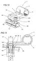
- Figures 12 and 13 show how the locking means 100 of each of the hinge bodies 2 and 3 consist, as is known, of at least one pair of screws 150 which can be fitted into first through-seats 151 in the brackets 4 and 5. These screws 150 may be locked in second, threaded seats 152 in a corresponding dowel 153 inserted in the frames 154 of the fixed frame IF and the mobile frame IM. These frames (only partially visible) in turn have through-holes 155 for the passage of the screws 150, with a diameter D1 greater than the diameter D2 of the second seats 152.
- each screw 150 has a countersunk centring profile PS, which engages with a matching countersink in the first seat 151.
- the central portion 156 of the shank 157 of each screw 151 has a diameter D3 substantially equal to the diameter D1 of the through-holes 155, allowing the screws to be locked, by interference, in the hole 155 when the screws 151 are screwed into the second holes 152 in the dowel 153.
- the portion 156 allows the elimination of the bushing which, as is known, is used for axial locking of the screw in the doorframe.
- the hinge therefore, fulfils the stated aims by means of a system for adjusting the hinge on three axes with simple adjustment movements, all effected with the hinge in use and without difficult lifting and subsequent refits.
- Said adjustment is extremely precise and continuous in terms of the positions which can be reached, allowing the fitter a simple, convenient view of the positions of the various hinge adjustment elements (screw on upper hinge body, threaded grub screw or bushings on lower hinge body).
- the hinge as a whole is not made too heavy by a large number of elements, whilst its safety is maintained within the optimum standards for its category.
- the system for fixing the hinge in place is extremely practical and safe and, at the same time, has one less element, thus simplifying assembly and reducing production and storage costs.
Landscapes
- Engineering & Computer Science (AREA)
- Mechanical Engineering (AREA)
- Hinges (AREA)
- Pivots And Pivotal Connections (AREA)
Abstract
Description
- The present invention relates to a hinge which is adjustable on three axes, for doorframes, in particular for heavy metal doorframes, that is to say, of the type which are large and, therefore, weigh more than standard interior models.
- The hinges used for the above-mentioned doorframes (that is to say, for exterior doors, gates, etc.), must satisfy special safety criteria and, therefore, differ from those used for normal (interior) doorframes. These differences are of a structural nature and consist of larger dimensions, partly necessary due to the greater weight of the doorframes, and the fact that they are fixed in place using screws which must be concealed by covering them with special anti-tampering covers. Moreover, due to the particular nature of the application, these hinges require adjustment to allow optimum adjustment of the position of the mobile frame relative to that of the fixed frame, given the reduced tolerance between them.
- Such hinges consist of two bodies, normally made of aluminium, which can be fixed to the mobile and fixed frames, and a steel hinge pin, which can be inserted in respective through-holes in the bodies inside a centring bushing (normally made of plastic and self-lubricating). The centre of the pin is fitted with a collar which is integral with the pin and whose diameter is greater than that of the through-holes in the bodies, to prevent the pin from exiting the seats in the bodies (see also patent IT - 1.221.237 by the Applicant).
- The bodies have brackets for fixing to the doorframe, through which there pass, in a direction perpendicular to the hinge pin, strong screws whose heads are housed in respective seats in the brackets.
- The latter, outside the screw heads, have guides defining seats for strong covers which slide parallel with the hinge pin. The covers conceal the screw heads completely and define a surface which makes contact with the entire cylindrical part of the hinge, in which there is the hole for the bushing, and the free end of the bracket which starts from this cylindrical part and bears the cover guides.
- The above-mentioned bushings normally consist of a cylindrical element, closed at one end, and a collar located at the open end. They also have an axial hole, offset relative to the longitudinal axis of the cylindrical element, and a set of projections or teeth, normally located on the outside of the bushing and immediately below the collar for contact with the hinge body, equidistant and designed to engage with matching seats made in the holes in the hinge bodies.
- The shape of the bushings allows the axis of the hinge pins to be moved on a plane parallel with the doorframe, by rotation of the pins about their axes, thus adjusting the position of the mobile frame relative to the fixed frame. This adjustment is carried out by raising the wing with the relative removal of the teeth from the seats of one or both bushings on the hinge, adjusting them in the new position, and finally re-inserting the bushings in the hinge bodies, simultaneously lowering the wing into the new position.
- However, this operation is awkward not only due to the difficulties involved in its performance, but also because the wings to be raised are, as indicated, very heavy and the first axial adjustment is not always the definitive one, meaning that the adjustment process is time consuming for the fitter or fitters.
- For this reason, the Applicant has designed a solution (see patent EP - 794.307) in which each bushing on the hinge consists of two separate elements, connected to one another by axial connecting means and free to rotate relative to one another. The first element is cylindrical and houses the portion of the pin, since it has a seat for holding the pin which is offset relative to a longitudinal axis of the bushing, whilst the other element defines a first collar whose diameter is greater than the diameter of the axial hole which houses the bushing. Adjustment means act upon the first element, being designed to vary its position relative to the second element by rotating the first element, with an action from outside the assembled and operating hinge body, between several stable conditions which are defined by grooves in the axial hole.
- This solution makes it easier to adjust the position between the mobile frame (which no longer has to be raised for each adjustment) and the fixed frame.
- However, both of the above-mentioned solutions allow adjustment of the position of the mobile frame in small steps, that is to say, according to the number of grooves on the circumference of the bushings and, respectively, in the seats of the hinge bodies, whilst the market for such products requires more precise adjustment of the doorframes, through a more continuous pin - bushing movement system able to obtain positioning which is more correct than the previous solutions.
- In addition, the hinge would preferably, for the purpose of structural completeness, allow adjustment of the height of the mobile frame relative to the fixed frame. This adjustment can be obtained through a solution known for some time now, using ring-shaped spacers, that is to say, washers, which may be inserted on the pin and have the same diameter as the pin collar, thus separating the two hinge bodies.
- This solution, although rapid, is disadvantageous and difficult to implement, since the wings to be raised are, as indicated, very heavy and the desired measurement is not always obtained with a single spacer insertion operation, meaning that the process is time consuming for the fitter or fitters. The rings are normally of given thicknesses, therefore, the adjustment of the height of the two hinge bodies is limited, according to the number of spacers inserted and is not continuous, as is often required during assembly of such doorframes.
- The aim of the present invention is, therefore, to overcome the above-mentioned disadvantages by providing a hinge for doorframes which has a simple structure, is extremely precise and rapid in adjusting the doorframe through three movements, that is to say, on the three axes of the hinge.
- Another aim of the present invention is to provide a hinge which is extremely practical and safe when assembled on the mobile and fixed doorframes.
- The technical features of the present invention, in accordance with the above aims, are apparent in the claims herein, and the advantages are more clearly described in the detailed description below, with reference to the accompanying drawings, which illustrate an embodiment of the invention, without limiting the scope off its application, and in which:
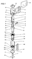
- Figure 1 is an exploded perspective view with some parts cut away to better illustrate others, of an adjustable hinge for doorframes, in accordance with the present invention;
- Figure 2 is a perspective top view of the assembled hinge illustrated in Figure 1;
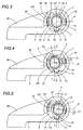
- Figures 3, 4 and 5 are top plan views, with some parts cut away to better illustrate others, of the hinge in the previous figures, in three different configurations which can be assumed by a hinge pin;
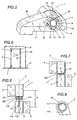
- Figure 6 is a schematic front view of a doorframe to which the hinge disclosed may be applied;
- Figures 7 and 8 are schematic front views of the hinge illustrated in Figure 11, in two different operating assembly positions on a doorframe;
- Figure 9 is a top plan view with some parts cut away to better illustrate others, of a detail of the hinge illustrated in Figure 11, that is to say, a lower hinge body;
- Figure 10 is an exploded perspective view, with some parts cut away to better illustrate others, of the lower part of an alternative embodiment of the hinge according to the present invention;
- Figure 11 is an exploded perspective view, with some parts cut away to better illustrate others, of another embodiment of the lower part of the hinge according to the present invention;
- Figure 12 is a perspective view with some parts cut away to better illustrate others, of the upper part of the hinge disclosed, illustrating means for fixing the hinge to a beam;
- Figure 13 is a cross-section of the hinge body and dowel illustrated in Figure 12;
- Figure 14 is a top plan view with some parts in cross-section, of another embodiment of a scaled-up part of the hinge illustrated in the previous figures.
-
- With reference to the accompanying drawings, and in particular Figures 1 and 2, the hinge disclosed may be used on "heavy" doorframes, such as exterior doors, main front doors, gates, etc.
- This hinge, indicated as a whole by the
numeral 1, comprises a first and asecond body brackets - The two
bodies pin 6 inserted, inside a first and a second lower and uppercylindrical bushing holes second bodies - Between the first bushing, which is the "upper" bushing 7, and the
relative hole 9, there are first means 11 for adjusting the position of thehinge pin 6, acting between the bushing and thehole 9, in such a way as to allow the position of thepin 6 relative to the longitudinal axis Z to move radially in both directions and on a plane P parallel with the doorframe. - As illustrated in Figures 3, 4 and 5, these first means 11 for adjusting the
pin 6 envisage, at least as regards thehinge body 2 defined by the upper part of thehinge 1 when assembly is complete, means 35 for rendering thebushing 7 and the portion of thepin 6 housed in it integral, so that they define a single adjustable body. - In addition, the
bushing 7 has an outerradial projection 12 which can engage in anotch 13 in the inner surface of thehole 9 in thehinge body 2. The engagement of theprojection 12 in thenotch 13 defines a pivoting point F (see Figure 3), in the style of a cam, for thefirst bushing 7, allowing it to perform a pendular movement in both directions together with the portion of thepin 6 housed in it, thanks torelative means 14, which can be operated from the outside, acting between thepin 6 and thehole 9 in such a way as to allow the above-mentioned adjustment of the position of thepin 6. - Obviously, the
second bushing 8 may also have adjustment means designed to allow the variation of the part of thepin 6 housed in it, in particular relative to an axis perpendicular to the plane P. - Such means are of the known type (for example, the
second bushing 8 is made with an eccentric hole) and are not, therefore, described here. - More specifically, the above-mentioned connecting means 35 consist of one or a pair of opposite (in the case of a pair)
flat surface sections 36 on the portion of thepin 6. Theseflat sections 36 connect, in such a way that they can slide, inside thebushing 7 which, in turn, has one or a pair offlat surfaces 37, allowing relative locking between thepin 6 and bushing 7. In other words, a single body is formed, which is adjustable and consists of the portion of thepin 6 and thebushing 7, upon which the pendular movement means 14 can act. - During assembly, the latter are positioned so that they are substantially transversal to the
radial projection 12 and thenotch 13. - The pendular movement means 14 consist of a
screw 15 which passes crosswise through thefirst bushing 7, which hascoaxial countersunk openings 16. Theseopenings 16 have initial dimensions smaller than the diameter of thescrew 15, so that they are deformed during assembly with thescrew 15, resulting in a self-locking action between thescrew 15 and thefirst bushing 7. Moreover, thescrew 15 is connected, in such a way that it can be screwed in and out, to thepin 6 which has a threaded through-hole 17. - The
screw 15 is mounted on thebushing 7 andpin 6 before the latter are housed inside thehole 9, in such a way that thescrew 15 is completely housed in thehole 9, with one of its ends in contact with an archedinner surface 18 of the hole and, the other end, partially opposite anarched slot 19, passing through thehinge body 2 and on asurface 20 opposite the above-mentionedarched surface 18. In this way, the screw can be turned in both directions and from outside the hinge body 2 (see arrow F1 in Figures 4 and 5) with a known type of tool, obtaining the pendular movement of the pin 6 - bushing 7 unit (see arrows F2 and F3 again in Figures 4 and 5) by moving, or rather, angling, thescrew 15 relative to the plane P parallel with the doorframe and intersecting the longitudinal axis X. - In the two directions, that is to say, of screwing in and unscrewing, the
screw 15 cannot move forwards or backwards along its longitudinal axis and, as a result, allows the angling of the pin 6 - bushing 7 unit through a sliding motion along thesurfaces - As illustrated in the accompanying drawings, the
inner surface 20 of thebushing 7, with theslot 19, has a groove 38 (defining a widening of the bushing hole) which extends over the entire length of thebushing 7. The groove is designed to hold at least the outer part of thehead 15T of thescrew 15 resting on the surface during the sliding which allows it to be housed in thebushing 7. This device may be preferable, since thehead 15T of thescrew 15 is normally cup-shaped and, therefore, makes contact with thecylindrical surface 20 only at one tangent point. Therefore, since thehead 15T is in an open space in the moment in which it is positioned next to theslot 19, it could move back several tenths until it rests on the edges of the slot, resulting in the possibility of a small amount of play on thescrew 15 in thehole 9, which could increase with an increase in the angle of thescrew 15 during the pendular movement. - By giving the groove 38 a well-defined depth and a length at least equal to the length of the
head 15T of thescrew 15, any play on thescrew 15 is eliminated when the latter is in contact with theinner surface 20 and close to theslot 19. - Instead of working the
cylindrical surface 20 of thehinge body 2 in this way, astabiliser 180 may be used (see Figure 14), inserted between thehead 15T of thescrew 15 and theinner surface 20. - As is clearly illustrated in Figure 14, the
stabiliser 180 is a matching fit, on one side, with the suitably-shaped head 15T, and on the other, makes contact with theinner surface 20. - The
stabiliser 180 also has a central through-hole 181, designed to allow operation of thescrew 15 from the outside. This alternative embodiment may be preferable, since it does not require any working on theinner surface 20 of thehinge body 2 and allows rapid, safe stabilising of thescrew 15 inside the hinge body. - The above-mentioned
radial projection 12 has an outer cam profile, for contact with thenotch 13, which is arched on three sides so that, during the pendular movement caused by thescrew 15, the position of thepin 6 can be maintained along the plane P parallel with the doorframe. The cam profile allows thepin 6 to move along the plane P, since theprojection 12 is raised inside thenotch 13, recovering the angle α or α' given by thescrew 15 to the position of the pin 6 -bushing 7 unit to obtain a relative movement T or T'. - The above-mentioned
hole 9 in thehinge body 2 substantially consists of afirst surface 21 in which thenotch 13 is made, the above-mentioned second 18 and third 20 arched surfaces, which are opposite one another, and upon which thescrew 15 acts, and a fourth,flat surface 22, opposite thefirst surface 21, with which thebushing 7 remains constantly in contact. - The centre of the
fourth surface 22 has a second,reference notch 23, in which, when thebushing 7 is fitted, asecond projection 24 on the bushing engages. The projection is designed to be deformed during the above-mentioned pendular movement. During assembly, this type of reference allows the fitter to insert the pin 6 -bushing 7 unit and screw 15 in thehole 9 more rapidly, with the elements already in the central position. - Figure 1 also illustrates how the
radial projection 12, thenotch 13 and thesecond notch 23 extend along the entire length of both thehinge body 2 and thebushing 7, whilst thesecond projection 24 extends only along part of the length of thefirst bushing 7. - The
slot 19, through which thescrew 15 can be operated, is then closed with a specialanti-tampering plate 30 which also covers the fixing screws on thebracket 4 of thehinge 2, and the upper part of thehinge body 2 is fitted with arelative cover 40. - Figure 1 also shows how the lower part of the
hinge 1 described up to now, that is to say, thesecond hinge body 3, closest to a tread surface P' (visible in Figure 6), is fitted withsecond means 111 for adjusting the axial distance, that is to say, the distance along the axis Z between the second hinge body and thefirst hinge body 2. The relative axial distance between the twohinge bodies - The second axial adjustment means 111 are located between the
second hinge body 3 and thesecond bushing 8, housed in thehole 10, so that in practice they allow said axial adjustment, from the outside, of the distance between the first andsecond hinge bodies - More specifically, as is again shown in Figure 1, the second axial adjustment means 111 consist of the
second bushing 8 with an outer portion, labelled 130, which is threaded and can be screwed into thesecond hinge body 3 which has a matchinginner thread 131. - This connection allows the
second bushing 8 to be raised or lowered by simply screwing in or unscrewing the second bushing. - In a preferred embodiment, the
second bushing 8 may have anouter thread 130 which extends over only part of its surface and close to anend collar 120 on the second bushing. - Again in Figure 1, the
second bushing 8 has aslot 132 in itsbase 133, which is designed to allow the insertion of a tool U (schematically illustrated, being of the known type) for adjusting, through rotation in both directions (see arrow F4), the second bushing about the longitudinal axis Z of thehinge 1. This allows thesecond bushing 8 to be raised or lowered with the relative screwing in or unscrewing of the second bushing. - To lock the
second bushing 8 in the desired position, the bushing has a pair ofnotches 134, positioned opposite one another and close to thebase 133 of thesecond bushing 8. During use, thesenotches 134 engage with a pair ofteeth 135 on acover 136 for closing thesecond hinge body 3, so as to lock thesecond bushing 8. Figure 1 illustrates how thesecond bushing 8 has fournotches 134, evenly distributed around thebase 133 to facilitate and speed up insertion and locking of thecover 136 from the outside. The twoteeth 135 are positioned and locked, through rotation, thanks to a set ofgrooves 160 inside thesecond hinge body 3, allowing theteeth 135 to lock thesecond bushing 8 and, at the same time, to be partially housed in said grooves. - Figure 10 shows a first alternative embodiment of the second axial adjustment means 111. In this embodiment, the second means 111 consist of a threaded positioning body or
plate 137, which can be screwed into the base of thesecond hinge body 3, the latter having aninner thread 138. - The centre of the
plate 137 has a through-seat 141 designed to allow the insertion of an operating tool U1 (of the known type and, therefore, only schematically illustrated) which can be used to turn theplate 137 in both directions (see arrow F5), thus, after assembly of the hinge, raising or lowering thesecond bushing 8 along the longitudinal axis Z. - In this specific case, the
second bushing 8 hasteeth 142 for locking and positioning, in rotation, distributed evenly over its outer circumference and engaging withseats 143 in the inner surface of thesecond hinge body 3. Theseteeth 142 can be used to adjust thepin 6 according to the axis Y perpendicular with the plane P, as described above. - Figure 11 illustrates another embodiment of the second adjustment means 111. This embodiment envisages the use of a
third bushing 112, inserted coaxially between thesecond bushing 7 and thesecond hinge body 3 which houses thesecond bushing 7. - The
third bushing 112 is acted upon bymeans 113 which move it along the above-mentioned longitudinal axis Z. These means are positioned between the third bushing and thesecond hinge body 3, so as to vary the position of thethird bushing 112 relative to thesecond hinge body 3 attached to the fixed frame IF. - In order to obtain this type of movement, the
third bushing 112 had a radial projection 114 (see Figures 9 and 11) along its outer circumference, extending longitudinally over a section T of the latter, and engaging in a matchingradial cavity 115, longitudinally passing through, and partially opening onto thehole 10 of thesecond hinge body 3. The suitably threadedcavity 115 allows engagement of the screw movement means 113 (defined by a suitable grub screw 119), acting on theradial projection 114 to move thethird bushing 112 away from or towards thesecond hinge body 3. - As illustrated in Figures 9 and 11, the
radial projection 114 on thethird bushing 112 and theradial cavity 115 in thesecond hinge body 3 have a circular cross-section. - To allow precision assembly of the
hinge 1, and a correct hinge starting position, thehole 10 in thesecond hinge body 3 for housing thethird bushing 112 has an extendededge 117, designed to define a seat which makes contact with and acts as a stop for acollar 118 on thethird bushing 112, when the bushing is fully inserted in the first body 2 (see Figure 7). - A hinge thus structured is assembled using conventional procedures, both on the fixed frame and the mobile frame, whilst the adjustment operations are carried out by moving the
screw 15, as described above and as illustrated in Figures 3 to 5, regarding the radial position on the plane P of the upper portion of thepin 6, that is to say, by screwing in or unscrewing thescrew 15 which allows the movement T or T' of thepin 6 until it reaches the desired position and is locked there. - On the
second hinge body 3, it is possible to obtain both a radial adjustment on the axis Y perpendicular with the plane P, by moving the position of the second bushing 8 (eccentric), and an adjustment along the vertical axis Z by, in the first embodiment, screwing in or unscrewing the second (threaded)bushing 8 from the base. This substantially lengthens the hinge along the axis Z and raises (or lowers) the mobile frame IM relative to the fixed frame IF. - As indicated, the adjustment of the centre to centre distance H is effected in the second embodiment illustrated in Figure 10 (thanks to the operation of the plate 137), and in the third embodiment illustrated in Figure 11, thanks to operation of the grub screw 119 (see arrow F6 in Figure 11) in the
radial cavity 115 using an appropriate tool and which, pressing against thecylindrical projection 114 of thethird bushing 112, allows the third bushing to be raised, thus also raising or lowering thesecond bushing 8 and thepin 6 thanks to the contact with thecollar 120 on thesecond bushing 8 and directly on thefirst bushing 7, located on opposite sides of thepin 6 collar 22 (see also arrow F7 in Figure 8) . This substantially lengthens the hinge along the axis Z and raises (or lowers) the mobile frame IM relative to the fixed frame IF (see arrow F8 in Figure 6). - Upon completing all adjustments, the operator may fit the
anti-tampering plates 30 and 30' on thebrackets hinge 1 to complete its assembly. - In the embodiments with axial adjustment, it is therefore possible to select continuous adjustment using the
grub screw 119 orplate 137, or fixed step adjustment with the threadedbushing 8, the latter taking into account the adjustment along the axis Y which is effected by thesecond bushing 8. - To complete this embodiment, Figures 12 and 13 show how the locking means 100 of each of the
hinge bodies screws 150 which can be fitted into first through-seats 151 in thebrackets screws 150 may be locked in second, threadedseats 152 in acorresponding dowel 153 inserted in theframes 154 of the fixed frame IF and the mobile frame IM. These frames (only partially visible) in turn have through-holes 155 for the passage of thescrews 150, with a diameter D1 greater than the diameter D2 of thesecond seats 152. - In the specific case illustrated, the
head 150T of eachscrew 150 has a countersunk centring profile PS, which engages with a matching countersink in thefirst seat 151. In addition, thecentral portion 156 of theshank 157 of eachscrew 151 has a diameter D3 substantially equal to the diameter D1 of the through-holes 155, allowing the screws to be locked, by interference, in thehole 155 when thescrews 151 are screwed into thesecond holes 152 in thedowel 153. In other words, theportion 156 allows the elimination of the bushing which, as is known, is used for axial locking of the screw in the doorframe. - This means that one part can be eliminated from the hinge set to be assembled.
- The hinge, therefore, fulfils the stated aims by means of a system for adjusting the hinge on three axes with simple adjustment movements, all effected with the hinge in use and without difficult lifting and subsequent refits.
- Said adjustment is extremely precise and continuous in terms of the positions which can be reached, allowing the fitter a simple, convenient view of the positions of the various hinge adjustment elements (screw on upper hinge body, threaded grub screw or bushings on lower hinge body).
- The hinge as a whole is not made too heavy by a large number of elements, whilst its safety is maintained within the optimum standards for its category.
- Such possibilities for adjustment give this type of hinge a complete structure, and mean that it meets extremely high standards of assembly and performance.
- The system for fixing the hinge in place is extremely practical and safe and, at the same time, has one less element, thus simplifying assembly and reducing production and storage costs.
- The invention described can be subject to modifications and variations without thereby departing from the scope of the inventive concept.
- Moreover, all the details of the invention may be substituted by technically equivalent elements.
Claims (25)
- An adjustable hinge for doorframes, the hinge (1) being of the type comprising at least a first and a second body (2, 3) which can be attached to a mobile frame (IM) and a fixed frame (IF) by means of brackets (4, 5) housing screw means (100); it being possible to insert a hinge pin (6), inside the first and second, lower and upper cylindrical centring bushings (7, 8), in respective axial through-holes (9, 10) in the first and second bodies (2, 3), said holes extending along a longitudinal axis (X); there being, between the first and second bushings (7, 8) and the holes (9, 10) means (11) for adjusting the position of the hinge pin (6), acting between the bushings and the holes (9, 10), allowing the position of the pin (6) relative to the longitudinal axis (X) to move radially in both directions parallel with the plane of the doorframe, the hinge being characterised in that the first means (11) for adjusting the pin (6) envisage, on at least one hinge body (2), means (35) for rendering the bushing (7) and the portion of the pin (6) housed in it integral, to define a single adjustable body, and in that the bushing (7) has an outer radial projection (12) engaging in a matching notch (13) in the inner surface of the hole (9) of the corresponding hinge body (2), being designed to define a pivoting point (F), in the style of a cam on the bushing, allowing the bushing and the portion of the pin (6) housed in it to perform a pendular movement, in both directions, thanks to relative means (14), which can be operated from the outside, acting between the pin (6) and the hole (9) in such a way as to allow said adjustment of the position of the pin (6).
- The hinge according to claim 1, in which second means (111) are envisaged for adjustment on a longitudinal axis (Z), acting on the hinge bodies (2, 3), the hinge being characterised in that the second adjustment means (111) are located on the other hinge body (3), acting on the latter in such a way as to vary the relative axial distance (H) between the first hinge body (2) and the second hinge body (3); said second axial adjustment means (111) being inserted between the second hinge body (3) and the second bushing (8), housed in the hole (10), allowing adjustment, from the outside, of the distance between the first and second hinge bodies (2, 3).
- The hinge according to claim 1, characterised in that the connecting means (35) consist of at least one flat surface section (36) on the portion of the pin (6), connecting, in such a way that they can slide, inside the bushing (7) which has at least one flat surface (37), allowing relative locking between the pin (6) and bushing (7).
- The hinge according to claim 3, characterised in that the connecting means (35) consist of a pair of flat surface sections (36), being located opposite one another on the portion of the pin (6), connecting, in such a way that they can slide, inside the bushing (7) which has matching flat inner surfaces (37) located opposite one another.
- The hinge according to claim 1, characterised in that, when the bushing (7) is fitted, the pendular movement means (14) are substantially transversal to the radial projection (12) and the notch (13).
- The hinge according to claim 1, characterised in that the means (14) for pendular movement of the pin (6) and bushing (7) consist of a screw (15) passing crosswise through the bushing (7), the latter having coaxial openings (16) and the screw being connected, in such a way that it can be screwed in and out, to the pin (6) which has a threaded through-hole (17); the screw (15) being completely housed in the hole (9) in the hinge body (2), one end of the screw being in contact with an arched inner surface (18) of the hole, and the other end of the screw (15) partially opposite an arched slot (19), passing through the hinge body (2) and on a surface (20) opposite the arched surface (18), thus allowing the screw to be moved in both directions from the outside, obtaining the pendular movement of the pin (6) - bushing (7) unit by moving, or rather, angling, the screw (15) relative to a plane (P) parallel with the doorframe and passing through the longitudinal axis (X).
- The hinge according to claim 6, characterised in that the inner surface (20) of the bushing (7), with said slot, has a cross-section revealing a groove (38) which extends over the entire length of the bushing (7), being designed to hold at least the outer part of the head (15T) of the screw (15) resting on the surface when the screw (15) is housed in the bushing (7), allowing constant contact between the head (15T) and the inner surface (20) when the head (15T) is positioned next to the slot (19).
- The hinge according to claim 7, characterised in that the length of the groove (38) is at least equal to the length of the head (15T) of the screw (15).
- The hinge according to claim 6, characterised in that between the head (15T) of the screw (15) and the inner surface (20) with the slot (19), there is a stabiliser (180), being a matching fit on one side with the head (15T), and on the other side making contact with the inner surface (20), said stabiliser (180) having a central through-hole (181) designed to allow operation of the screw (15) from the outside.
- The hinge according to claim 1, characterised in that the radial projection (12) has an outer cam profile, for contact with the notch (13), that is to say, the profile is arched so that, during said pendular movement, the position of the pin (6) can be maintained along a plane (P) parallel with the doorframe and intersecting the longitudinal axis (X).
- The hinge according to claim 1, characterised in that the hinge body (2) with the hole (9) which has the notch (13) in a first surface (21) of the hole, has a second (18) and a third (20) arched surface, being opposite one another and acted upon by the pendular movement means (14), and a fourth, flat surface (22), being opposite the first surface (21) and making contact with the bushing (7) when the latter performs its pendular movement.
- The hinge according to claim 11, characterised in that the centre of the fourth surface (22) has a second, reference notch (23) which, during assembly of the bushing (7), engages with a second projection (24) on the bushing, the latter being designed to be deformed during said pendular movement.
- The hinge according to claim 1, characterised in that the radial projection (12) and the notch (13) extend along the entire length of the hinge body (2) and the bushing (7).
- The hinge according to claim 2, characterised in that the second axial adjustment means (111) consist of a third bushing (112), housing the second bushing (8) and inserted coaxially between the said bushing and the second hinge body (3); the third bushing (112) being moved by means (113) for moving said third bushing along the longitudinal axis (Z), said means inserted between the third bushing (112) and the second hinge body (3), and designed to allow a variation along the longitudinal axis (Z) of the position of the third bushing (112) relative to the hinge body (3).
- The hinge according to claim 14, characterised in that the third bushing (112) has a radial projection (114) along its outer circumference, extending longitudinally over a section (T) of the latter, which can engage in a matching radial cavity (115), longitudinally passing through and opening onto the hole (10) of the second hinge body (3); it being possible to screw the screw movement means (116) into the cavity (115), said screw movement means acting on the radial projection (114).
- The hinge according to claim 15, characterised in that the radial projection (114) of the third bushing (112) and the radial cavity (115) in the second hinge body (3) have a circular cross-section.
- The hinge according to claim 14, characterised in that the hole (10) for housing the third bushing (112) in the second hinge body (3) has an extended edge (117), being designed to define a seat which makes contact with and acts as a stop for a collar (118) on the third bushing (112), when the bushing is fully inserted in the second body (3).
- The hinge according to claim 2, characterised in that the second axial adjustment means (111) consist of the second bushing (8) with an outer portion (130) which is threaded and can be screwed into the second hinge body (3), the latter having a matching inner thread (131).
- The hinge according to claim 18, characterised in that the second bushing (8) has a slot (132) in its base (133), being designed to allow the insertion of a tool (U) for adjusting, through rotation in both directions, the second bushing about a longitudinal axis (Z) of the hinge (1).
- The hinge according to claim 18, characterised in that the second bushing (8) has at least one pair of notches (134), positioned opposite one another and close to the base (133) of the second bushing (8) and being designed so that during use, they engage with a pair of teeth (135) on a cover (136) for closing the second hinge body (3), locking the second bushing (8) in the preset position.
- The hinge according to claim 18, characterised in that the thread (130) on the outside of the second bushing (8) extends over only part of its surface and close to an end collar (120) on the second bushing.
- The hinge according to claim 20, characterised in that the second bushing (8) has four notches (134) evenly distributed around said base (133).
- The hinge according to claim 2, characterised in that the second axial adjustment means (111) consist of a threaded positioning body or plate (137), which can be screwed into the second hinge body (3) which has an inner thread (138); the plate (137) having a through-seat (141) designed to allow the insertion of an operating tool (U1) designed to allow rotation of the plate (137), in both directions, thus raising or lowering the second bushing (8) along the longitudinal axis (Z) after the hinge has been assembled.
- The hinge according to claim 23, characterised in that the second bushing (8) has teeth (142) for locking and positioning, in rotation, being located on its outer circumference and engaging with seats (143) in the inner surface of the second hinge body (3).
- The hinge according to claim 1, where the locking means (100) of each of the hinge bodies (2, 3) consist of at least one pair of screws (150) which can be fitted into first through-seats (151) in the brackets (4, 5), it being possible to screw and lock the screws in second seats (152) in a corresponding dowel (153) inserted in the frames (154) of the fixed frame (IF) and the mobile frame (IM), the latter, in turn, having through-holes (155) with a diameter (D1) greater than the diameter (D2) of the second seats (152), the hinge being characterised in that the head (150T) of each screw (150) has a countersunk centring profile (PS), engaging with a matching countersink in the first seat (151) and also being characterised in that a central portion (156) of the shank (157) of each screw (151) has a diameter (D3) substantially equal to the diameter (D1) of the through-holes (155), allowing the screws to be locked in the hole, by interference, when the screws (151) are screwed into the second holes (152) in the dowel (153).
Applications Claiming Priority (2)
| Application Number | Priority Date | Filing Date | Title |
|---|---|---|---|
| IT1998BO000563A IT1304490B1 (en) | 1998-10-05 | 1998-10-05 | ADJUSTABLE HINGE FOR WINDOWS. |
| ITBO980563 | 1998-10-05 |
Publications (3)
| Publication Number | Publication Date |
|---|---|
| EP0992647A2 true EP0992647A2 (en) | 2000-04-12 |
| EP0992647A3 EP0992647A3 (en) | 2001-06-27 |
| EP0992647B1 EP0992647B1 (en) | 2004-01-07 |
Family
ID=11343435
Family Applications (1)
| Application Number | Title | Priority Date | Filing Date |
|---|---|---|---|
| EP99830625A Expired - Lifetime EP0992647B1 (en) | 1998-10-05 | 1999-10-05 | Adjustable hinge for door frames |
Country Status (5)
| Country | Link |
|---|---|
| EP (1) | EP0992647B1 (en) |
| AT (1) | ATE257540T1 (en) |
| DE (1) | DE69914036T2 (en) |
| ES (1) | ES2212511T3 (en) |
| IT (1) | IT1304490B1 (en) |
Cited By (22)
| Publication number | Priority date | Publication date | Assignee | Title |
|---|---|---|---|---|
| FR2836527A1 (en) * | 2002-02-28 | 2003-08-29 | Tryba | DEVICE FOR SOLIDARIZING AND ANCHORING AN ELEMENT IN A GROOVE |
| EP1455042A1 (en) * | 2003-02-21 | 2004-09-08 | Master S.R.L. | Adjustable hinge for window or door casing |
| WO2004081326A1 (en) * | 2003-03-10 | 2004-09-23 | Soeviknes Ole Gunnar | Hinge |
| EP1640538A1 (en) | 2004-09-17 | 2006-03-29 | GSG INTERNATIONAL S.p.A. | An adjustable door hinge |
| WO2006060018A1 (en) * | 2004-12-02 | 2006-06-08 | Stanley Chung | Adjustable door hinge |
| WO2007003251A1 (en) * | 2005-07-06 | 2007-01-11 | Dr. Hahn Gmbh & Co. Kg | Hinge for doors, windows or similar |
| DE102005055395B3 (en) * | 2005-11-17 | 2007-04-26 | BKV Bau- und kunststofftechnische Entwicklungs- und Vertriebsgesellschaft mit beschränkter Haftung | Side adjustment device for door/window turning band has axle pin seated in bearing eye with adjustment pin seated in bushing consisting of two parts which move relative to each other by turning adjustment pin, keeping lengthwise alignment |
| EP1598510A3 (en) * | 2004-05-18 | 2007-05-02 | GSG International S.p.A. | An adjustable door hinge |
| WO2007090502A1 (en) * | 2006-02-10 | 2007-08-16 | Dr. Hahn Gmbh & Co. Kg | Hinge for doors, windows or the like |
| EP1666688A3 (en) * | 2004-09-06 | 2010-04-28 | Dr. Hahn GmbH & Co. KG | Hinge for windows, doors and the like |
| GB2464950A (en) * | 2008-10-30 | 2010-05-05 | Window Fab & Fixing Supplies | Adjusting hinge |
| EP2186980A1 (en) | 2008-11-12 | 2010-05-19 | GSG INTERNATIONAL S.p.A. | An adjustable hinge for doors and windows |
| ITBS20090139A1 (en) * | 2009-07-24 | 2011-01-25 | Co A R S R L | ADJUSTABLE HINGES FOR WINDOWS |
| ITBO20090825A1 (en) * | 2009-12-24 | 2011-06-25 | Gsg Int Spa | HINGE FOR HEAVY DUSTS |
| ITVR20100229A1 (en) * | 2010-12-01 | 2012-06-02 | Piva Group S P A | HINGE PARTICULARLY FOR PORTS OF PREFABRICATED BUILDINGS |
| ITMI20111515A1 (en) * | 2011-08-08 | 2013-02-09 | Masterlab S R L Unipersonale | ADJUSTABLE HINGE FOR WINDOWS |
| CN102995990A (en) * | 2012-12-25 | 2013-03-27 | 山东国强五金科技有限公司 | Three-dimensional hinge for aluminium-alloy flat-opening door |
| EP2881531A1 (en) | 2013-12-09 | 2015-06-10 | Jos. Berchtold AG | Folding doors |
| JP2018076713A (en) * | 2016-11-10 | 2018-05-17 | 株式会社共栄金物製作所 | Adjustable flag hinge |
| GB2560549A (en) * | 2017-03-15 | 2018-09-19 | Gore Products Ltd | Hinge |
| WO2019197118A1 (en) * | 2018-04-11 | 2019-10-17 | Dr. Hahn Gmbh & Co. Kg | Hinge for fastening a wing to a frame such that it can pivot about a hinge axis |
| DE102023133582A1 (en) * | 2023-11-30 | 2025-06-05 | Sunshine Vans GmbH | Hinge element for attachment to a door frame and hinge with such a hinge element |
Families Citing this family (3)
| Publication number | Priority date | Publication date | Assignee | Title |
|---|---|---|---|---|
| DE202017103105U1 (en) * | 2017-05-23 | 2018-08-24 | Dr. Hahn Gmbh & Co. Kg | Band to hinged about a hinge axis fixing a wing to a frame |
| IT201900007554A1 (en) | 2019-05-30 | 2020-11-30 | Giesse Spa | ADJUSTABLE HINGE FOR WINDOWS. |
| CN113833372B (en) * | 2021-10-07 | 2024-07-05 | 广东哥尼迪家居五金有限公司 | Needle type hinge easy to install |
Citations (2)
| Publication number | Priority date | Publication date | Assignee | Title |
|---|---|---|---|---|
| IT1221237B (en) | 1988-03-16 | 1990-06-21 | Giesse Spa | HINGE FOR DOORS AND SIMILAR SAFETY FRAMES |
| EP0794307A1 (en) | 1996-03-04 | 1997-09-10 | GIESSE S.p.A. | A hinge for metal doors and windows |
Family Cites Families (1)
| Publication number | Priority date | Publication date | Assignee | Title |
|---|---|---|---|---|
| DE4022532C1 (en) * | 1990-07-16 | 1991-12-19 | Dr. Hahn Gmbh & Co. Kg, 4050 Moenchengladbach, De |
-
1998
- 1998-10-05 IT IT1998BO000563A patent/IT1304490B1/en active
-
1999
- 1999-10-05 ES ES99830625T patent/ES2212511T3/en not_active Expired - Lifetime
- 1999-10-05 EP EP99830625A patent/EP0992647B1/en not_active Expired - Lifetime
- 1999-10-05 AT AT99830625T patent/ATE257540T1/en not_active IP Right Cessation
- 1999-10-05 DE DE69914036T patent/DE69914036T2/en not_active Expired - Lifetime
Patent Citations (2)
| Publication number | Priority date | Publication date | Assignee | Title |
|---|---|---|---|---|
| IT1221237B (en) | 1988-03-16 | 1990-06-21 | Giesse Spa | HINGE FOR DOORS AND SIMILAR SAFETY FRAMES |
| EP0794307A1 (en) | 1996-03-04 | 1997-09-10 | GIESSE S.p.A. | A hinge for metal doors and windows |
Cited By (30)
| Publication number | Priority date | Publication date | Assignee | Title |
|---|---|---|---|---|
| FR2836527A1 (en) * | 2002-02-28 | 2003-08-29 | Tryba | DEVICE FOR SOLIDARIZING AND ANCHORING AN ELEMENT IN A GROOVE |
| EP1455042A1 (en) * | 2003-02-21 | 2004-09-08 | Master S.R.L. | Adjustable hinge for window or door casing |
| US7500286B2 (en) * | 2003-03-10 | 2009-03-10 | Ole Gunnar Soviknes | Hinge |
| WO2004081326A1 (en) * | 2003-03-10 | 2004-09-23 | Soeviknes Ole Gunnar | Hinge |
| EP1598510A3 (en) * | 2004-05-18 | 2007-05-02 | GSG International S.p.A. | An adjustable door hinge |
| EP1666688A3 (en) * | 2004-09-06 | 2010-04-28 | Dr. Hahn GmbH & Co. KG | Hinge for windows, doors and the like |
| EP1640538A1 (en) | 2004-09-17 | 2006-03-29 | GSG INTERNATIONAL S.p.A. | An adjustable door hinge |
| RU2367757C2 (en) * | 2004-09-17 | 2009-09-20 | ДжиЭсДжи Интернэшнл С.п.А. | Adjustable door hinge |
| WO2006060018A1 (en) * | 2004-12-02 | 2006-06-08 | Stanley Chung | Adjustable door hinge |
| RU2380505C2 (en) * | 2005-07-06 | 2010-01-27 | Др. Хан Гмбх Унд Ко. Кг | Hinge for doors, windows or like |
| WO2007003251A1 (en) * | 2005-07-06 | 2007-01-11 | Dr. Hahn Gmbh & Co. Kg | Hinge for doors, windows or similar |
| DE102005055395B3 (en) * | 2005-11-17 | 2007-04-26 | BKV Bau- und kunststofftechnische Entwicklungs- und Vertriebsgesellschaft mit beschränkter Haftung | Side adjustment device for door/window turning band has axle pin seated in bearing eye with adjustment pin seated in bushing consisting of two parts which move relative to each other by turning adjustment pin, keeping lengthwise alignment |
| WO2007090502A1 (en) * | 2006-02-10 | 2007-08-16 | Dr. Hahn Gmbh & Co. Kg | Hinge for doors, windows or the like |
| GB2464950A (en) * | 2008-10-30 | 2010-05-05 | Window Fab & Fixing Supplies | Adjusting hinge |
| GB2464950B (en) * | 2008-10-30 | 2013-09-18 | Window Fab & Fixing Supplies | Adjusting hinge |
| RU2519999C2 (en) * | 2008-10-30 | 2014-06-20 | Виндоу Фабрикейшн Энд Фиксинг Саплайз Лимитед | Adjustable hinge |
| EP2186980A1 (en) | 2008-11-12 | 2010-05-19 | GSG INTERNATIONAL S.p.A. | An adjustable hinge for doors and windows |
| ITBS20090139A1 (en) * | 2009-07-24 | 2011-01-25 | Co A R S R L | ADJUSTABLE HINGES FOR WINDOWS |
| ITBO20090825A1 (en) * | 2009-12-24 | 2011-06-25 | Gsg Int Spa | HINGE FOR HEAVY DUSTS |
| EP2339102A1 (en) | 2009-12-24 | 2011-06-29 | GSG International S.p.A. | Hinge for heavy doors, windows or the like |
| ITVR20100229A1 (en) * | 2010-12-01 | 2012-06-02 | Piva Group S P A | HINGE PARTICULARLY FOR PORTS OF PREFABRICATED BUILDINGS |
| EP2557258A1 (en) | 2011-08-08 | 2013-02-13 | MasterLAB S.r.l. - Unipersonale | Adjustable hinge for window or door frames |
| ITMI20111515A1 (en) * | 2011-08-08 | 2013-02-09 | Masterlab S R L Unipersonale | ADJUSTABLE HINGE FOR WINDOWS |
| CN102995990A (en) * | 2012-12-25 | 2013-03-27 | 山东国强五金科技有限公司 | Three-dimensional hinge for aluminium-alloy flat-opening door |
| EP2881531A1 (en) | 2013-12-09 | 2015-06-10 | Jos. Berchtold AG | Folding doors |
| JP2018076713A (en) * | 2016-11-10 | 2018-05-17 | 株式会社共栄金物製作所 | Adjustable flag hinge |
| GB2560549A (en) * | 2017-03-15 | 2018-09-19 | Gore Products Ltd | Hinge |
| GB2560549B (en) * | 2017-03-15 | 2022-05-25 | Gore Products Ltd | Hinge |
| WO2019197118A1 (en) * | 2018-04-11 | 2019-10-17 | Dr. Hahn Gmbh & Co. Kg | Hinge for fastening a wing to a frame such that it can pivot about a hinge axis |
| DE102023133582A1 (en) * | 2023-11-30 | 2025-06-05 | Sunshine Vans GmbH | Hinge element for attachment to a door frame and hinge with such a hinge element |
Also Published As
| Publication number | Publication date |
|---|---|
| DE69914036D1 (en) | 2004-02-12 |
| ATE257540T1 (en) | 2004-01-15 |
| EP0992647B1 (en) | 2004-01-07 |
| ES2212511T3 (en) | 2004-07-16 |
| ITBO980563A1 (en) | 2000-04-05 |
| EP0992647A3 (en) | 2001-06-27 |
| DE69914036T2 (en) | 2004-11-25 |
| IT1304490B1 (en) | 2001-03-19 |
Similar Documents
| Publication | Publication Date | Title |
|---|---|---|
| EP0992647B1 (en) | Adjustable hinge for door frames | |
| EP1672155B1 (en) | An adjustable hinge for doors and windows. | |
| US5694665A (en) | Adjustable hinge | |
| US3538539A (en) | Automatic doorstop hinge | |
| US5701636A (en) | Adjustable door hinge | |
| US6484363B1 (en) | Adjustable hinge | |
| JP2001012131A (en) | Hinge for opening/closing door or window frame | |
| EP4019716B1 (en) | Door leaf with flush lever handle fitting and a method for mounting a door fitting | |
| US5375296A (en) | Adjustable hinge and installation method for inset doors | |
| GB2276204A (en) | Adjustable hinge | |
| WO2014066929A1 (en) | Adjustable hinge | |
| EP1091066A2 (en) | Hinge for doors or windows | |
| EP3757322B1 (en) | Concealed adjustable hinge | |
| EP1598510B1 (en) | An adjustable door hinge | |
| US7059020B2 (en) | Hinge for doors and similar construction components | |
| KR102532350B1 (en) | Bottom hinge device for opening and closing | |
| EP0728892A1 (en) | Bearing for a wing | |
| GB2227521A (en) | Adjustable hinges | |
| EP2924211B1 (en) | Adjustable hinge for doors or windows | |
| DE4218430A1 (en) | Adjustable hinge for windows or doors | |
| EP4464862A1 (en) | Hinge for a door or window | |
| EP3976913B1 (en) | Adjustable hinge for doors and windows | |
| US20240287840A1 (en) | Hinge with adjustable friction | |
| GB2641105A (en) | Adjustable hinge | |
| KR102517192B1 (en) | Gap Adjustment Structure of the Hinged Door |
Legal Events
| Date | Code | Title | Description |
|---|---|---|---|
| PUAI | Public reference made under article 153(3) epc to a published international application that has entered the european phase |
Free format text: ORIGINAL CODE: 0009012 |
|
| AK | Designated contracting states |
Kind code of ref document: A2 Designated state(s): AT BE CH CY DE DK ES FI FR GB GR IE IT LI LU MC NL PT SE |
|
| AX | Request for extension of the european patent |
Free format text: AL;LT;LV;MK;RO;SI |
|
| PUAL | Search report despatched |
Free format text: ORIGINAL CODE: 0009013 |
|
| AK | Designated contracting states |
Kind code of ref document: A3 Designated state(s): AT BE CH CY DE DK ES FI FR GB GR IE IT LI LU MC NL PT SE |
|
| AX | Request for extension of the european patent |
Free format text: AL;LT;LV;MK;RO;SI |
|
| RIC1 | Information provided on ipc code assigned before grant |
Free format text: 7E 05D 7/04 A, 7E 05D 7/00 B |
|
| RAP1 | Party data changed (applicant data changed or rights of an application transferred) |
Owner name: GSG INTERNATIONAL S.P.A. |
|
| 17P | Request for examination filed |
Effective date: 20011019 |
|
| AKX | Designation fees paid |
Free format text: AT BE CH CY DE DK ES FI FR GB GR IE IT LI LU MC NL PT SE |
|
| 17Q | First examination report despatched |
Effective date: 20021105 |
|
| GRAH | Despatch of communication of intention to grant a patent |
Free format text: ORIGINAL CODE: EPIDOS IGRA |
|
| GRAS | Grant fee paid |
Free format text: ORIGINAL CODE: EPIDOSNIGR3 |
|
| GRAA | (expected) grant |
Free format text: ORIGINAL CODE: 0009210 |
|
| AK | Designated contracting states |
Kind code of ref document: B1 Designated state(s): AT BE CH CY DE DK ES FI FR GB GR IE IT LI LU MC NL PT SE |
|
| PG25 | Lapsed in a contracting state [announced via postgrant information from national office to epo] |
Ref country code: NL Free format text: LAPSE BECAUSE OF FAILURE TO SUBMIT A TRANSLATION OF THE DESCRIPTION OR TO PAY THE FEE WITHIN THE PRESCRIBED TIME-LIMIT Effective date: 20040107 Ref country code: LI Free format text: LAPSE BECAUSE OF FAILURE TO SUBMIT A TRANSLATION OF THE DESCRIPTION OR TO PAY THE FEE WITHIN THE PRESCRIBED TIME-LIMIT Effective date: 20040107 Ref country code: FI Free format text: LAPSE BECAUSE OF FAILURE TO SUBMIT A TRANSLATION OF THE DESCRIPTION OR TO PAY THE FEE WITHIN THE PRESCRIBED TIME-LIMIT Effective date: 20040107 Ref country code: CY Free format text: LAPSE BECAUSE OF FAILURE TO SUBMIT A TRANSLATION OF THE DESCRIPTION OR TO PAY THE FEE WITHIN THE PRESCRIBED TIME-LIMIT Effective date: 20040107 Ref country code: CH Free format text: LAPSE BECAUSE OF FAILURE TO SUBMIT A TRANSLATION OF THE DESCRIPTION OR TO PAY THE FEE WITHIN THE PRESCRIBED TIME-LIMIT Effective date: 20040107 Ref country code: BE Free format text: LAPSE BECAUSE OF FAILURE TO SUBMIT A TRANSLATION OF THE DESCRIPTION OR TO PAY THE FEE WITHIN THE PRESCRIBED TIME-LIMIT Effective date: 20040107 Ref country code: AT Free format text: LAPSE BECAUSE OF FAILURE TO SUBMIT A TRANSLATION OF THE DESCRIPTION OR TO PAY THE FEE WITHIN THE PRESCRIBED TIME-LIMIT Effective date: 20040107 |
|
| REG | Reference to a national code |
Ref country code: GB Ref legal event code: FG4D |
|
| REG | Reference to a national code |
Ref country code: CH Ref legal event code: EP |
|
| REG | Reference to a national code |
Ref country code: IE Ref legal event code: FG4D |
|
| REF | Corresponds to: |
Ref document number: 69914036 Country of ref document: DE Date of ref document: 20040212 Kind code of ref document: P |
|
| PG25 | Lapsed in a contracting state [announced via postgrant information from national office to epo] |
Ref country code: SE Free format text: LAPSE BECAUSE OF FAILURE TO SUBMIT A TRANSLATION OF THE DESCRIPTION OR TO PAY THE FEE WITHIN THE PRESCRIBED TIME-LIMIT Effective date: 20040407 Ref country code: DK Free format text: LAPSE BECAUSE OF FAILURE TO SUBMIT A TRANSLATION OF THE DESCRIPTION OR TO PAY THE FEE WITHIN THE PRESCRIBED TIME-LIMIT Effective date: 20040407 |
|
| REG | Reference to a national code |
Ref country code: GR Ref legal event code: EP Ref document number: 20040401006 Country of ref document: GR |
|
| NLV1 | Nl: lapsed or annulled due to failure to fulfill the requirements of art. 29p and 29m of the patents act | ||
| REG | Reference to a national code |
Ref country code: CH Ref legal event code: PL |
|
| REG | Reference to a national code |
Ref country code: ES Ref legal event code: FG2A Ref document number: 2212511 Country of ref document: ES Kind code of ref document: T3 |
|
| PLBQ | Unpublished change to opponent data |
Free format text: ORIGINAL CODE: EPIDOS OPPO |
|
| PLBI | Opposition filed |
Free format text: ORIGINAL CODE: 0009260 |
|
| 26 | Opposition filed |
Opponent name: DR. HAHN GMBH & CO. KG Effective date: 20040708 |
|
| PG25 | Lapsed in a contracting state [announced via postgrant information from national office to epo] |
Ref country code: LU Free format text: LAPSE BECAUSE OF NON-PAYMENT OF DUE FEES Effective date: 20041005 Ref country code: IE Free format text: LAPSE BECAUSE OF NON-PAYMENT OF DUE FEES Effective date: 20041005 Ref country code: GB Free format text: LAPSE BECAUSE OF NON-PAYMENT OF DUE FEES Effective date: 20041005 |
|
| ET | Fr: translation filed | ||
| PG25 | Lapsed in a contracting state [announced via postgrant information from national office to epo] |
Ref country code: MC Free format text: LAPSE BECAUSE OF NON-PAYMENT OF DUE FEES Effective date: 20041031 |
|
| PLAX | Notice of opposition and request to file observation + time limit sent |
Free format text: ORIGINAL CODE: EPIDOSNOBS2 |
|
| PLAX | Notice of opposition and request to file observation + time limit sent |
Free format text: ORIGINAL CODE: EPIDOSNOBS2 |
|
| PLBB | Reply of patent proprietor to notice(s) of opposition received |
Free format text: ORIGINAL CODE: EPIDOSNOBS3 |
|
| GBPC | Gb: european patent ceased through non-payment of renewal fee |
Effective date: 20041005 |
|
| REG | Reference to a national code |
Ref country code: IE Ref legal event code: MM4A |
|
| PLAY | Examination report in opposition despatched + time limit |
Free format text: ORIGINAL CODE: EPIDOSNORE2 |
|
| PLAB | Opposition data, opponent's data or that of the opponent's representative modified |
Free format text: ORIGINAL CODE: 0009299OPPO |
|
| R26 | Opposition filed (corrected) |
Opponent name: DR. HAHN GMBH & CO. KG Effective date: 20040708 |
|
| PLBC | Reply to examination report in opposition received |
Free format text: ORIGINAL CODE: EPIDOSNORE3 |
|
| PLCK | Communication despatched that opposition was rejected |
Free format text: ORIGINAL CODE: EPIDOSNREJ1 |
|
| PLBN | Opposition rejected |
Free format text: ORIGINAL CODE: 0009273 |
|
| STAA | Information on the status of an ep patent application or granted ep patent |
Free format text: STATUS: OPPOSITION REJECTED |
|
| 27O | Opposition rejected |
Effective date: 20061124 |
|
| PG25 | Lapsed in a contracting state [announced via postgrant information from national office to epo] |
Ref country code: PT Free format text: LAPSE BECAUSE OF NON-PAYMENT OF DUE FEES Effective date: 20040607 |
|
| PGFP | Annual fee paid to national office [announced via postgrant information from national office to epo] |
Ref country code: GR Payment date: 20101101 Year of fee payment: 12 |
|
| PGFP | Annual fee paid to national office [announced via postgrant information from national office to epo] |
Ref country code: FR Payment date: 20111115 Year of fee payment: 13 |
|
| REG | Reference to a national code |
Ref country code: GR Ref legal event code: ML Ref document number: 20040401006 Country of ref document: GR Effective date: 20130508 |
|
| REG | Reference to a national code |
Ref country code: FR Ref legal event code: ST Effective date: 20130628 |
|
| PG25 | Lapsed in a contracting state [announced via postgrant information from national office to epo] |
Ref country code: FR Free format text: LAPSE BECAUSE OF NON-PAYMENT OF DUE FEES Effective date: 20121031 Ref country code: GR Free format text: LAPSE BECAUSE OF NON-PAYMENT OF DUE FEES Effective date: 20130508 |
|
| PGFP | Annual fee paid to national office [announced via postgrant information from national office to epo] |
Ref country code: ES Payment date: 20151126 Year of fee payment: 17 |
|
| PG25 | Lapsed in a contracting state [announced via postgrant information from national office to epo] |
Ref country code: ES Free format text: LAPSE BECAUSE OF FAILURE TO SUBMIT A TRANSLATION OF THE DESCRIPTION OR TO PAY THE FEE WITHIN THE PRESCRIBED TIME-LIMIT Effective date: 20040107 |
|
| REG | Reference to a national code |
Ref country code: ES Ref legal event code: FD2A Effective date: 20181119 |
|
| RIC2 | Information provided on ipc code assigned after grant |
Ipc: E05D 7/00 20060101ALI20010504BHEP Ipc: E05D 7/04 20060101AFI20000111BHEP |
|
| PG25 | Lapsed in a contracting state [announced via postgrant information from national office to epo] |
Ref country code: ES Free format text: LAPSE BECAUSE OF FAILURE TO SUBMIT A TRANSLATION OF THE DESCRIPTION OR TO PAY THE FEE WITHIN THE PRESCRIBED TIME-LIMIT Effective date: 20161006 |
|
| PGFP | Annual fee paid to national office [announced via postgrant information from national office to epo] |
Ref country code: IT Payment date: 20181024 Year of fee payment: 20 |
|
| PGFP | Annual fee paid to national office [announced via postgrant information from national office to epo] |
Ref country code: DE Payment date: 20181228 Year of fee payment: 20 |
|
| REG | Reference to a national code |
Ref country code: DE Ref legal event code: R071 Ref document number: 69914036 Country of ref document: DE |