EP0992425A2 - Dachkühlung - Google Patents
Dachkühlung Download PDFInfo
- Publication number
- EP0992425A2 EP0992425A2 EP99203286A EP99203286A EP0992425A2 EP 0992425 A2 EP0992425 A2 EP 0992425A2 EP 99203286 A EP99203286 A EP 99203286A EP 99203286 A EP99203286 A EP 99203286A EP 0992425 A2 EP0992425 A2 EP 0992425A2
- Authority
- EP
- European Patent Office
- Prior art keywords
- cooling
- ceiling
- tube
- panel
- tube coil
- Prior art date
- Legal status (The legal status is an assumption and is not a legal conclusion. Google has not performed a legal analysis and makes no representation as to the accuracy of the status listed.)
- Granted
Links
Images


Classifications
-
- F—MECHANICAL ENGINEERING; LIGHTING; HEATING; WEAPONS; BLASTING
- F24—HEATING; RANGES; VENTILATING
- F24F—AIR-CONDITIONING; AIR-HUMIDIFICATION; VENTILATION; USE OF AIR CURRENTS FOR SCREENING
- F24F5/00—Air-conditioning systems or apparatus not covered by F24F1/00 or F24F3/00, e.g. using solar heat or combined with household units such as an oven or water heater
- F24F5/0089—Systems using radiation from walls or panels
-
- B—PERFORMING OPERATIONS; TRANSPORTING
- B63—SHIPS OR OTHER WATERBORNE VESSELS; RELATED EQUIPMENT
- B63J—AUXILIARIES ON VESSELS
- B63J2/00—Arrangements of ventilation, heating, cooling, or air-conditioning
- B63J2/02—Ventilation; Air-conditioning
- B63J2/04—Ventilation; Air-conditioning of living spaces
-
- F—MECHANICAL ENGINEERING; LIGHTING; HEATING; WEAPONS; BLASTING
- F24—HEATING; RANGES; VENTILATING
- F24F—AIR-CONDITIONING; AIR-HUMIDIFICATION; VENTILATION; USE OF AIR CURRENTS FOR SCREENING
- F24F5/00—Air-conditioning systems or apparatus not covered by F24F1/00 or F24F3/00, e.g. using solar heat or combined with household units such as an oven or water heater
- F24F5/0089—Systems using radiation from walls or panels
- F24F5/0092—Systems using radiation from walls or panels ceilings, e.g. cool ceilings
Definitions
- the present invention relates to a system for heat regulation of spaces on board a ship.
- the invention particularly relates to a so-called cooling ceiling which supplies heat to or carries away heat from a cabin in, for example, a cruiser.
- Water is many times more efficient than air when it comes to supplying/transferring heat energy. This is made use of, inter alia, in air-conditioning of cruisers for the purpose of reducing the space requirement for the air-conditioning equipment.
- the area of a tube which conducts water need only be made in a size which is about 1/300 as large as the corresponding area of an air duct and is still capable of transferring the same cooling or heating capacity due to the higher density and specific heat of the water.
- Water may equally be replaced by some other liquid cooling agent.
- the term cooling water shall therefore be construed in a broad sense and comprise all liquid cooling agents.
- Fan coils comprise a water/air heat exchanger (wax) and a small circulating fan.
- wax water/air heat exchanger
- a small circulating fan is supplied with waterborne cooling (heating) effect and is preferably placed above the inner ceiling immediately underneath the deck positioned above, or in the toilet module of the cabin.
- Pre-treated ventilating air is supplied to the cabin via the fan-coil unit or directly to the cabin from a centrally located air-treatment unit.
- Cold water from a cooling machine is supplied to the fan-coil unit from a system of tubes.
- the circulating fan causes the cabin air to circulate through the fan-coil unit, whereby the air is cooled or heated, according to the requirement.
- the ventilating air supplied to the cabin may be dried, humidified, cooled or preheated in the central unit.
- a cooling ceiling usually comprises a plurality of panels on which are fixed a tube coil for passage of a liquid cooling agent. Both the tube and the panel are made of metal to achieve good thermal conductivity from the cooling agent.
- a relatively cold ceiling surface is thus created (typically 14-17 °C) which absorbs the radiation heat of the warmer room air.
- a minor part of the heat transfer to the cold water in the tube coils takes place by convection.
- the cooling ceiling may be fed with hot water such that the room air is heated by radiation heat which is supplied to the room air from the hot water via the ceiling panels. Pretreated air is supplied to the room to ensure the ventilation requirement.
- the ceiling temperature is kept above the current dew-point temperature.
- This type of tempering is experienced as very comfortable, especially in the summer in that the body is cooled both by convection and radiation. In that way it is possible to raise the temperature in the room one or a few degrees without the indoor climate being experienced as worse than otherwise, which is positive from the energy-saving point of view.
- the cooling ceiling technique is especially well suited at great thermal loads as, for example, heat radiation from large window surfaces since the efficiency increases in relation to the radiation yield. In this way, the heat radiation is efficiently "sucked” up, from a window surface warmed by the sun, by the cooling ceiling without first heating the air in the room.
- the cold water which is present on board is always kept at about 6-7 °C except in the winter when 12-13 °C is a frequently used temperature. These temperatures are controlled by the on-board cooling machine and by the need of being able to dehumidify the ventilating air to a sufficient extent before it is supplied to the interior of the ship. Supplying the cooling ceiling with water of a temperature of 6-7 °C would, admittedly, provide an efficient cooling device but is unsuitable since it would be experienced as very uncomfortable to have such a cold surface in the cabin or in some other space. In addition, the cooling ceiling would assume a temperature below the dew point of the cabin air and condensation would arise also without allowing exterior air into the space.
- a suitable temperature of the cooling ceiling would instead be about 15-10 degrees.
- the cooling water must have a temperature of about 12-15 degrees. This would mean that the water which has cost a great deal of energy to cool down would have to be reheated by an extra heat exchanger and hot water or electricity before it could be distributed to a cooling ceiling.
- a cooling ceiling comprises a plurality of cooling panels of extruded aluminium, to which cooling water tubes are fixed on the upper side.
- the cooling water tubes are jointed at the ends so as to form a loop covering the ceiling surface and wherein both ends are connected to a cooling unit.
- the cooling panels then make direct contact with an inner ceiling of thin sheet. During mounting, the cooling panels thus have to be mounted first, whereupon the cooling tubes are jointed. This operation has to be carried out in the narrow space between the roof and the inner ceiling.
- the object of the presents invention is to suggest solutions to a heat-regulation system for a ship' cabin which offers a higher comfort and which, in a better way than before, economizes on the available energy on board a ship.
- a cooling ceiling is suggested which, without the occurrence of condensation, offers passengers a comfortable indoor climate during voyages in tropical as well as arctic waters.
- the cooling ceiling shall be easy to install and dismantle so as to make possible access to and service of other components which are concealed by the ceiling.
- a second aspect of the invention relates to a method for heat regulation of a ship's cabin with the assistance of a cooling ceiling.
- a thermal resistance is introduced between the cooling agent and the ceiling panel, whereby the already existing cooling water on board the ship may be utilized.
- the resistance introduced implies that less heat per unit of time is transported from the cooling agent to the ceiling panel and vice versa.
- This thermal resistance is achieved by surrounding the cooling water with a thermal insulation, the thermal conductivity of which is inferior to that of, for example, copper.
- This is achieved by insulating the cooling water tube or by quite simply manufacturing the cooling water tube of a material which exhibits good thermal insulation.
- the cooling water tube is advantageously made of a polymer such as, for example, crosslinked polyethylene (XLPE). Such a tube is adapted to form a jointless coil over the ceiling.
- the available cooling water which has a temperature of about 6-7 degrees, is then fed directly into such a tube coil without preheating. Since the polymer is much inferior to metal as thermal conductor, an outside temperature of the tube coil is obtained which results in condensation being avoided while at the same time the cooling ceiling temperature may be kept within 15-18 °C, which is ideal from the point of view of comfort.
- Tubes of polymer or plastic are much lighter than tubes of metal, which is of importance on board a ship where weight is an optimization factor.
- plastic tubes are bendable and may easily be installed without prefabrication of coils, as is the case with metal tubes.
- Tubes of, for example, XLPE may be manufactured with a layer which prevents the penetration of oxygen. The oxygen content of the water may thus be kept low, thus preventing corrosion and the growth of microorganisms.
- Plastic tubes are very resistant to vibrations and withstand deformations and variations in temperature very well.
- a continuous tube of, for example, XLPE is adapted to be fixed to a plurality of cooling panels so as to form a jointless coil for the cooling water.
- the cooling panels are made of a thin metal such as, for example, an extruded aluminium profile and are brought to make butt contact with the inner ceiling panels of thin sheet.
- the profile may be formed with a groove into which the tube may be simply pressed from below. In this way, neither the panel nor the cooling tube need to be installed from the narrow space above the inner ceiling, but the whole installation takes place from the cabin.
- the continuous plastic tube is fed from a reel.
- the finished coil is connected to other tube coils in the same space or directly to the water system from the cooling machine.
- the cooling panel with its longitudinal slots for the cooling tube is attached directly to the deck or to the frame which sustains the ceiling panels.
- the cooling panel is arranged at such a relative height that it will make butt contact with the upper side of the respective inner ceiling panel when these are finally installed in the cabin or the space where the cooling ceiling has been installed.
- an extruded aluminium profile with "resilient slots" for the XLPE tube may also comprise shallow dovetail slots for a magnetic polymer tape which provides increased contact between the panel and the cooling panel.
- Other profiles, such as resilient, openable or flexible may also be utilized.
- the problems with condensation can be avoided by separating the inner ceiling from the cooling panels, in addition to shutting off the cooling water.
- the inner ceiling consists of thin sheet panels which constitute only a small part of the total thermal mass. If this is separated from the rest of the thermal mass, the sheet may be rapidly heated by the inrushing hot air so that no condensation problems arise.
- the initial condensation which may have time to form on the panel surface disappears in a very short time because of energy supplied from the exterior air.
- a device which separates the panel from the cooling panel may comprise a flexible diaphragm which is placed between the panel and the holder profile. This diaphragm may be caused to expand with the aid of compressed air or other pressurized medium.
- An air gap of one or a few millimetres is sufficient to attain good thermal separation between the panel and the cold parts of the cooling ceiling.
- the inner ceiling is covered with a thick mineral wool insulation on the upper side.
- the mineral wool also functions as thermal insulation for the cooling ceiling and prevents condensation on the holder profile or the tube coil.
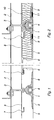
- the cooling ceiling schematically shown in Figure 1 comprises a cooling panel 1 which is suspended from a primary supporting system 2 with an attachment device 3.
- the cooling panel 1 supports a cooling tube 4, in which flows a cooling liquid, which may be water.
- An inner ceiling 5 makes contact with the under side of the cooling panel and thermal butt contact with the cooling panel.
- the inner ceiling is formed with folded-in ridges 6, which are adapted to be fixed in angle brackets 7 belonging to a secondary supporting system 8, which may be the same as the primary supporting system 2.
- the ridges 6 are adapted to introduce a spring force into the inner ceiling, by means of which the inner ceiling is pressed against the cooling panel.
- the cooling panel on its side, is formed with flanges 9, the under sides of which are plane and adapted to make butt contact with the equally plane inner ceiling.
- the cooling tube 4 is made of an insulating material, for example of a crosslinked polyethylene (XLPE).
- the cooling ceiling as shown in Figure 2 comprises, in all essentials, the sane parts as the cooling ceiling according to Figure 1.
- a cooling panel 1 thus supports a cooling tube 4 and is arranged in butt contact with an inner ceiling 5.
- the cooling ceiling is formed with an insulation 10 of, for example, mineral wool which covers the upper side of the inner ceiling and the cooling panel.
- the purpose of the insulation is threefold. According to a first purpose, it shall insulate the cooling panel against heat transport such that moisture does not condense on the upper side of the cooling ceiling. According to a second purpose, the insulation shall function as a sound absorbent, whereby sound in the cabin is attenuated. According to a third purpose, finally, the mineral wool shall constitute a fire insulation.
- the cooling panel in the example is also designed with attachment devices 11 to rigidly secure the base against the cooling panel.
- These attachment devices may advantageously be arranged of magnetic tapes placed in dovetail-shaped slots in the cooling panel.
- the magnetic force which arises between the wedged-in magnetic tapes and the inner ceiling, which must be made of magnetizable sheet, is sufficient to create the thermal contact between cooling panel and inner ceiling.
- the magnetic tapes also make it exceedingly simple to dismantle the inner ceiling.
- FIG. 3 shows an advantageous embodiment of a cooling panel 4.
- the panel is made as a continuous profile of extruded aluminium.
- the profile is inversely symmetrical around a vertical section.
- Each side comprises a flange 9 with a plane under side adapted to make contact with an inner ceiling.
- Symmetrically around the cross section the profile also comprises two claws, which are adapted to partly surround and secure a cooling tube.
- the claws have been given a thin profile to increase the elastic bendability such that the claws embrace the cooling tube with a spring force.
- the heat which is to be transported to or from the cooling tube must, in order to reach the inner ceiling, pass an area 13 at the root of the claws.
- This area may be dimensioned to impart to the transport route a desired thermal resistance such that a desired thermal inertia is achieved between cooling tube and inner ceiling. This possibility is available, in addition to the fact that the actual cooling tube as such contains a thermal inertia.
- the inner ceiling In cabins, where hot moist air may suddenly rush in, for example when a balcony door is opened, the inner ceiling must be rapidly heated in order for the condensation of the moist air not to take place on the inner ceiling.
- the inner ceiling which is preferably made of a shin sheet, thus constitutes a very small thermal mass. Relatively seen, a very small amount of energy is required to heat up the sheet itself.
- the cooling panel is arranged with expansion devices, which temporarily break the thermal contact between cooling panel and inner ceiling.
- the expanding devices may be simply designed as an elastic hose 16 drawn in a longitudinally extending slot across the magnetic tapes 11.
- the magnetic tapes When the hose is brought to expand, for example by supplying compressed air, the magnetic tapes are brought to bulge outwards. This bulge results in the inner ceiling, despite a maintained magnetic contact, being moved away from the cooling panel.
- the inner ceiling thus exposed is rapidly heated up by the inrushing hot air, whereby the dew point is never passed and thus no condensation is deposited on the inner ceiling.
- moisture may condense on the inner ceiling but rapidly evaporates when the inner ceiling is heated.
- FIG. 5 shows an example of a circuit diagram for connection of cooling water and air supply.
- a supply conduit 20 for cooling water distributes, under tropical conditions, water with a temperature of 6-7 °C. Under arctic conditions, hot water with a temperature of 30-50 °C is instead distributed.
- the cooling water is supplied to the cooling panels through a coil 21 composed of the cooling tubes. At the end of the coil, the cooling water passes through a heat-exchanger 22, a stop valve 23, before the water is returned along a discharge conduit 24.
- the stop valve is adapted to temporarily shut off the water supply when the climate in the cabin is rapidly changed.
- Conditioned air is supplied to the cabin through a supply channel 25.
- the air passes through the heat-exchanger 22 before it flows out into the cabin. This provides for good possibilities of tempering the supply air correctly and according to individual requirements.
- the air is returned in a return-air channel (not shown).
- a cooling ceiling according to the invention offers a considerably simplified installation and increased safety against leakage of water.
- the cooling panels are cut into lengths and placed in their final positions, whereupon the plastic tube in the form of a continuous hose on a reel is pressed into the groove, provided for that purpose, in the panel. This work may very well be carried out at a late stage of the construction work.
- the thermal inertia in the cooling ceiling is dimensioned such that the available cooling water on board (Chilled Water) may be used directly.
- the wall thickness and the material in the cooling tube may be utilized as well as also the geometrical shape of the profile of the cooling panel.
- a tube of a polymeric material is chosen.
- the thermal conductivity of the polymeric material is much inferior to that of copper. This implies that a thermal resistance is introduced between cooling agent and cooling panel. The resistance reduces the thermal flow such that a difference of about 8-12 degrees is obtained between the inner and outer sides of the cooling tube.
- insulated channels are used for distribution of supply air (fresh air) in a cruiser since the air, which passes through a cooling battery in the central unit to be dehumidified and cooled, is very cold (about 11 °C in the summer). Without insulation, the cooling capacity would be lost and condensation would appear outside the channels.
- non-insulated channels may be used between the central unit and the respective space. This results in the channel system becoming considerably less expensive, less voluminous and considerably lighter.
- hot air is supplied in non-insulated channels in the cabin.
- a small convenient heat exchanger is connected in series with the coil in the inner ceiling at the respective space such that this heat exchanger is fed with return water from the cooling ceiling. If the cooling ceiling is then fed with water with a temperature of 6-7 degrees, the return water may be counted on to maintain a temperature of 9-10 °C after having passed through the tube coil. This water is allowed to continue through the heat exchanger and will then cool the supply air from, for example, 20 °C to 14 °C, which often is a suitable so-called undertemperature. The temperature of the return water has then risen to 13-14 °C, which is a suitable (necessary) return-water temperature to feed back to the cooling machine.
Landscapes
- Engineering & Computer Science (AREA)
- Combustion & Propulsion (AREA)
- Mechanical Engineering (AREA)
- Chemical & Material Sciences (AREA)
- General Engineering & Computer Science (AREA)
- Sustainable Development (AREA)
- Life Sciences & Earth Sciences (AREA)
- Ocean & Marine Engineering (AREA)
- Building Environments (AREA)
- Transformer Cooling (AREA)
- Filling Or Discharging Of Gas Storage Vessels (AREA)
- Debugging And Monitoring (AREA)
- Superconductors And Manufacturing Methods Therefor (AREA)
Applications Claiming Priority (2)
| Application Number | Priority Date | Filing Date | Title |
|---|---|---|---|
| SE9803468 | 1998-10-08 | ||
| SE9803468A SE513564C2 (sv) | 1998-10-08 | 1998-10-08 | Kyltak |
Publications (3)
| Publication Number | Publication Date |
|---|---|
| EP0992425A2 true EP0992425A2 (de) | 2000-04-12 |
| EP0992425A3 EP0992425A3 (de) | 2001-12-19 |
| EP0992425B1 EP0992425B1 (de) | 2004-09-01 |
Family
ID=20412911
Family Applications (1)
| Application Number | Title | Priority Date | Filing Date |
|---|---|---|---|
| EP99203286A Expired - Lifetime EP0992425B1 (de) | 1998-10-08 | 1999-10-07 | Dachkühlung |
Country Status (4)
| Country | Link |
|---|---|
| EP (1) | EP0992425B1 (de) |
| AT (1) | ATE275064T1 (de) |
| DE (1) | DE69919800D1 (de) |
| SE (1) | SE513564C2 (de) |
Cited By (5)
| Publication number | Priority date | Publication date | Assignee | Title |
|---|---|---|---|---|
| EP1371915A2 (de) * | 2002-06-10 | 2003-12-17 | EMCO Klima GmbH & Co. KG | Klimadecke mit PCM und dazu verwendbarer Beutel |
| EP1489241A1 (de) * | 2003-06-20 | 2004-12-22 | Schneider Dämmtechnik AG | Anordnung zum Befestigen von Deckenelementen |
| WO2009136423A1 (en) * | 2008-05-09 | 2009-11-12 | Five T S.R.L. | Modular panel for the formation of systems for ambient cooling or heating |
| ITVI20090075A1 (it) * | 2009-04-03 | 2010-10-04 | Fral S R L | Deumidificatore a condensazione |
| CN110539873A (zh) * | 2019-09-25 | 2019-12-06 | 中国船舶重工集团公司第七一九研究所 | 一种船舶自适应调节的自流进水装置 |
Family Cites Families (6)
| Publication number | Priority date | Publication date | Assignee | Title |
|---|---|---|---|---|
| BE627123A (de) * | 1962-01-18 | |||
| DE4032113A1 (de) * | 1990-10-10 | 1992-04-16 | Koester Helmut | Heiz- oder kuehlbare deckenelemente |
| US6910526B1 (en) * | 1995-10-06 | 2005-06-28 | Barcol-Air Ag | Contact element and ceiling element for a heating and cooling ceiling |
| DE29612617U1 (de) * | 1996-07-20 | 1996-09-12 | Trox Gmbh Geb | Kühldecke zur Raumkühlung |
| DE29702410U1 (de) * | 1997-02-12 | 1997-04-10 | Trox Gmbh Geb | Flächenelement zur thermischen Behandlung eines Raumes |
| US5931381A (en) * | 1997-05-23 | 1999-08-03 | Fiedrich; Joachim | For radiant floor, wall and ceiling hydronic heating and/or cooling systems using metal plates that are heated or cooled by attached tubing that is fed hot or cold water, techniques of improving performance and avoiding condensation when cooling |
-
1998
- 1998-10-08 SE SE9803468A patent/SE513564C2/sv not_active IP Right Cessation
-
1999
- 1999-10-07 EP EP99203286A patent/EP0992425B1/de not_active Expired - Lifetime
- 1999-10-07 DE DE69919800T patent/DE69919800D1/de not_active Expired - Lifetime
- 1999-10-07 AT AT99203286T patent/ATE275064T1/de not_active IP Right Cessation
Non-Patent Citations (1)
| Title |
|---|
| None |
Cited By (8)
| Publication number | Priority date | Publication date | Assignee | Title |
|---|---|---|---|---|
| EP1371915A2 (de) * | 2002-06-10 | 2003-12-17 | EMCO Klima GmbH & Co. KG | Klimadecke mit PCM und dazu verwendbarer Beutel |
| EP1371915A3 (de) * | 2002-06-10 | 2004-02-18 | EMCO Klima GmbH & Co. KG | Klimadecke mit PCM und dazu verwendbarer Beutel |
| EP1489241A1 (de) * | 2003-06-20 | 2004-12-22 | Schneider Dämmtechnik AG | Anordnung zum Befestigen von Deckenelementen |
| WO2009136423A1 (en) * | 2008-05-09 | 2009-11-12 | Five T S.R.L. | Modular panel for the formation of systems for ambient cooling or heating |
| CN102016433A (zh) * | 2008-05-09 | 2011-04-13 | 五T责任有限公司 | 用于形成环境冷却或加热系统的模块化面板 |
| ITVI20090075A1 (it) * | 2009-04-03 | 2010-10-04 | Fral S R L | Deumidificatore a condensazione |
| CN110539873A (zh) * | 2019-09-25 | 2019-12-06 | 中国船舶重工集团公司第七一九研究所 | 一种船舶自适应调节的自流进水装置 |
| CN110539873B (zh) * | 2019-09-25 | 2024-05-24 | 中国船舶重工集团公司第七一九研究所 | 一种船舶自适应调节的自流进水装置 |
Also Published As
| Publication number | Publication date |
|---|---|
| EP0992425B1 (de) | 2004-09-01 |
| EP0992425A3 (de) | 2001-12-19 |
| SE9803468D0 (sv) | 1998-10-08 |
| DE69919800D1 (de) | 2004-10-07 |
| SE513564C2 (sv) | 2000-10-02 |
| SE9803468L (sv) | 2000-04-09 |
| ATE275064T1 (de) | 2004-09-15 |
Similar Documents
| Publication | Publication Date | Title |
|---|---|---|
| US5897079A (en) | Air curtain insulating system for aircraft cabin | |
| US9365279B2 (en) | Fuselage of an aircraft or spacecraft and method of actively insulating such a fuselage | |
| EP3499139B1 (de) | Äusseres fassadenverkleidungssystem | |
| US20170036769A1 (en) | Aircraft insulation system and aircraft air conditioning and insulation arrangement | |
| EP0992425B1 (de) | Dachkühlung | |
| EP1077870B1 (de) | Ventilation | |
| US4157112A (en) | Air conditioning method | |
| WO1999051918A1 (en) | Ventilation system | |
| EP0916575A2 (de) | Klimaanlage für Schiffe | |
| JP5335376B2 (ja) | 冷暖房システム | |
| JPH0448430Y2 (de) | ||
| JP4698204B2 (ja) | 建物の室内空調システム | |
| JP2006132823A (ja) | 建物の室内空調システム | |
| KR20120004239U (ko) | 덕트 기능을 구비한 선실용 옷장 | |
| JPH06229034A (ja) | 建築物における躯体構造 | |
| EP1076626B1 (de) | System zur klimatisierung von raümen, insbesondere in schiffen und fahrtschiff-kabinen | |
| EP1626898B1 (de) | Belüftungssystem und verfahren für ein schiff, bei dem niedrigtemperaturzurluft vor dem eintritt in einen raum mit raumluft gemischt wird | |
| JPH11255122A (ja) | 鉄道車両とその空調ダクトシステム | |
| JP6224881B2 (ja) | 放射空調システム | |
| CN215001964U (zh) | 一种疫情防控常态化下的地下车站分散式空调系统 | |
| GB2375815A (en) | Underfloor heating and cooling for a raised access floor | |
| JP2995028B2 (ja) | 室内暖房構造 | |
| JP7033486B2 (ja) | パーソナル空調システム | |
| JPH11108394A (ja) | 空調システム | |
| WO2002006735A1 (en) | Supply air device and method for ventilation where room air is induced to the fresh air flow |
Legal Events
| Date | Code | Title | Description |
|---|---|---|---|
| PUAI | Public reference made under article 153(3) epc to a published international application that has entered the european phase |
Free format text: ORIGINAL CODE: 0009012 |
|
| AK | Designated contracting states |
Kind code of ref document: A2 Designated state(s): AT BE CH CY DE DK ES FI FR GB GR IE IT LI LU MC NL PT SE |
|
| AX | Request for extension of the european patent |
Free format text: AL;LT;LV;MK;RO;SI |
|
| PUAL | Search report despatched |
Free format text: ORIGINAL CODE: 0009013 |
|
| AK | Designated contracting states |
Kind code of ref document: A3 Designated state(s): AT BE CH CY DE DK ES FI FR GB GR IE IT LI LU MC NL PT SE |
|
| AX | Request for extension of the european patent |
Free format text: AL;LT;LV;MK;RO;SI |
|
| RIC1 | Information provided on ipc code assigned before grant |
Free format text: 7B 63J 2/04 A, 7B 63J 2/12 B, 7F 24F 5/00 B |
|
| 17P | Request for examination filed |
Effective date: 20020629 |
|
| AKX | Designation fees paid |
Free format text: AT BE CH CY DE DK ES FI FR GB GR IE IT LI LU MC NL PT SE |
|
| DBV | Designated contracting states (deleted) | ||
| REG | Reference to a national code |
Ref country code: DE Ref legal event code: 8566 |
|
| 17Q | First examination report despatched |
Effective date: 20030122 |
|
| GRAP | Despatch of communication of intention to grant a patent |
Free format text: ORIGINAL CODE: EPIDOSNIGR1 |
|
| RBV | Designated contracting states (corrected) |
Designated state(s): AT BE CH CY DE DK ES FI FR GB GR IE IT LI LU MC NL PT SE |
|
| GRAS | Grant fee paid |
Free format text: ORIGINAL CODE: EPIDOSNIGR3 |
|
| GRAA | (expected) grant |
Free format text: ORIGINAL CODE: 0009210 |
|
| AK | Designated contracting states |
Kind code of ref document: B1 Designated state(s): AT BE CH CY DE DK ES FI FR GB GR IE IT LI LU MC NL PT SE |
|
| PG25 | Lapsed in a contracting state [announced via postgrant information from national office to epo] |
Ref country code: NL Free format text: LAPSE BECAUSE OF FAILURE TO SUBMIT A TRANSLATION OF THE DESCRIPTION OR TO PAY THE FEE WITHIN THE PRESCRIBED TIME-LIMIT Effective date: 20040901 Ref country code: LI Free format text: LAPSE BECAUSE OF FAILURE TO SUBMIT A TRANSLATION OF THE DESCRIPTION OR TO PAY THE FEE WITHIN THE PRESCRIBED TIME-LIMIT Effective date: 20040901 Ref country code: ES Free format text: LAPSE BECAUSE OF FAILURE TO SUBMIT A TRANSLATION OF THE DESCRIPTION OR TO PAY THE FEE WITHIN THE PRESCRIBED TIME-LIMIT Effective date: 20040901 Ref country code: CY Free format text: LAPSE BECAUSE OF FAILURE TO SUBMIT A TRANSLATION OF THE DESCRIPTION OR TO PAY THE FEE WITHIN THE PRESCRIBED TIME-LIMIT Effective date: 20040901 Ref country code: CH Free format text: LAPSE BECAUSE OF FAILURE TO SUBMIT A TRANSLATION OF THE DESCRIPTION OR TO PAY THE FEE WITHIN THE PRESCRIBED TIME-LIMIT Effective date: 20040901 Ref country code: BE Free format text: LAPSE BECAUSE OF FAILURE TO SUBMIT A TRANSLATION OF THE DESCRIPTION OR TO PAY THE FEE WITHIN THE PRESCRIBED TIME-LIMIT Effective date: 20040901 Ref country code: AT Free format text: LAPSE BECAUSE OF FAILURE TO SUBMIT A TRANSLATION OF THE DESCRIPTION OR TO PAY THE FEE WITHIN THE PRESCRIBED TIME-LIMIT Effective date: 20040901 |
|
| REG | Reference to a national code |
Ref country code: GB Ref legal event code: FG4D |
|
| REG | Reference to a national code |
Ref country code: CH Ref legal event code: EP |
|
| REG | Reference to a national code |
Ref country code: IE Ref legal event code: FG4D |
|
| PG25 | Lapsed in a contracting state [announced via postgrant information from national office to epo] |
Ref country code: LU Free format text: LAPSE BECAUSE OF NON-PAYMENT OF DUE FEES Effective date: 20041007 Ref country code: IE Free format text: LAPSE BECAUSE OF NON-PAYMENT OF DUE FEES Effective date: 20041007 |
|
| REF | Corresponds to: |
Ref document number: 69919800 Country of ref document: DE Date of ref document: 20041007 Kind code of ref document: P |
|
| PG25 | Lapsed in a contracting state [announced via postgrant information from national office to epo] |
Ref country code: MC Free format text: LAPSE BECAUSE OF NON-PAYMENT OF DUE FEES Effective date: 20041031 |
|
| PG25 | Lapsed in a contracting state [announced via postgrant information from national office to epo] |
Ref country code: SE Free format text: LAPSE BECAUSE OF FAILURE TO SUBMIT A TRANSLATION OF THE DESCRIPTION OR TO PAY THE FEE WITHIN THE PRESCRIBED TIME-LIMIT Effective date: 20041201 Ref country code: GR Free format text: LAPSE BECAUSE OF FAILURE TO SUBMIT A TRANSLATION OF THE DESCRIPTION OR TO PAY THE FEE WITHIN THE PRESCRIBED TIME-LIMIT Effective date: 20041201 Ref country code: GB Free format text: LAPSE BECAUSE OF NON-PAYMENT OF DUE FEES Effective date: 20041201 Ref country code: DK Free format text: LAPSE BECAUSE OF FAILURE TO SUBMIT A TRANSLATION OF THE DESCRIPTION OR TO PAY THE FEE WITHIN THE PRESCRIBED TIME-LIMIT Effective date: 20041201 |
|
| PG25 | Lapsed in a contracting state [announced via postgrant information from national office to epo] |
Ref country code: DE Free format text: LAPSE BECAUSE OF FAILURE TO SUBMIT A TRANSLATION OF THE DESCRIPTION OR TO PAY THE FEE WITHIN THE PRESCRIBED TIME-LIMIT Effective date: 20041202 |
|
| NLV1 | Nl: lapsed or annulled due to failure to fulfill the requirements of art. 29p and 29m of the patents act | ||
| REG | Reference to a national code |
Ref country code: CH Ref legal event code: PL |
|
| PLBE | No opposition filed within time limit |
Free format text: ORIGINAL CODE: 0009261 |
|
| STAA | Information on the status of an ep patent application or granted ep patent |
Free format text: STATUS: NO OPPOSITION FILED WITHIN TIME LIMIT |
|
| GBPC | Gb: european patent ceased through non-payment of renewal fee |
Effective date: 20041201 |
|
| REG | Reference to a national code |
Ref country code: IE Ref legal event code: MM4A |
|
| ET | Fr: translation filed | ||
| 26N | No opposition filed |
Effective date: 20050602 |
|
| PGFP | Annual fee paid to national office [announced via postgrant information from national office to epo] |
Ref country code: FR Payment date: 20051010 Year of fee payment: 7 |
|
| PGFP | Annual fee paid to national office [announced via postgrant information from national office to epo] |
Ref country code: FI Payment date: 20051013 Year of fee payment: 7 |
|
| REG | Reference to a national code |
Ref country code: FR Ref legal event code: TP |
|
| PG25 | Lapsed in a contracting state [announced via postgrant information from national office to epo] |
Ref country code: FI Free format text: LAPSE BECAUSE OF NON-PAYMENT OF DUE FEES Effective date: 20061007 |
|
| PGFP | Annual fee paid to national office [announced via postgrant information from national office to epo] |
Ref country code: IT Payment date: 20061031 Year of fee payment: 8 |
|
| REG | Reference to a national code |
Ref country code: FR Ref legal event code: ST Effective date: 20070629 |
|
| PG25 | Lapsed in a contracting state [announced via postgrant information from national office to epo] |
Ref country code: PT Free format text: LAPSE BECAUSE OF NON-PAYMENT OF DUE FEES Effective date: 20050201 |
|
| PG25 | Lapsed in a contracting state [announced via postgrant information from national office to epo] |
Ref country code: FR Free format text: LAPSE BECAUSE OF NON-PAYMENT OF DUE FEES Effective date: 20061031 |
|
| PG25 | Lapsed in a contracting state [announced via postgrant information from national office to epo] |
Ref country code: IT Free format text: LAPSE BECAUSE OF NON-PAYMENT OF DUE FEES Effective date: 20071007 |