EP0991455B1 - Traitement d'une substance par un fluide dense (par exemple, un fluide supercritique) - Google Patents
Traitement d'une substance par un fluide dense (par exemple, un fluide supercritique) Download PDFInfo
- Publication number
- EP0991455B1 EP0991455B1 EP98930901A EP98930901A EP0991455B1 EP 0991455 B1 EP0991455 B1 EP 0991455B1 EP 98930901 A EP98930901 A EP 98930901A EP 98930901 A EP98930901 A EP 98930901A EP 0991455 B1 EP0991455 B1 EP 0991455B1
- Authority
- EP
- European Patent Office
- Prior art keywords
- solution
- pressure
- expansion
- solute
- dense fluid
- Prior art date
- Legal status (The legal status is an assumption and is not a legal conclusion. Google has not performed a legal analysis and makes no representation as to the accuracy of the status listed.)
- Expired - Lifetime
Links
Images


Classifications
-
- B—PERFORMING OPERATIONS; TRANSPORTING
- B01—PHYSICAL OR CHEMICAL PROCESSES OR APPARATUS IN GENERAL
- B01D—SEPARATION
- B01D9/00—Crystallisation
- B01D9/0018—Evaporation of components of the mixture to be separated
- B01D9/0022—Evaporation of components of the mixture to be separated by reducing pressure
-
- B—PERFORMING OPERATIONS; TRANSPORTING
- B01—PHYSICAL OR CHEMICAL PROCESSES OR APPARATUS IN GENERAL
- B01J—CHEMICAL OR PHYSICAL PROCESSES, e.g. CATALYSIS OR COLLOID CHEMISTRY; THEIR RELEVANT APPARATUS
- B01J2/00—Processes or devices for granulating materials, e.g. fertilisers in general; Rendering particulate materials free flowing in general, e.g. making them hydrophobic
- B01J2/02—Processes or devices for granulating materials, e.g. fertilisers in general; Rendering particulate materials free flowing in general, e.g. making them hydrophobic by dividing the liquid material into drops, e.g. by spraying, and solidifying the drops
Definitions
- This invention relates to a.process and apparatus for the precipitation of solid solutes from solution. More particularly the invention relates to a process for the modification of the particle form of a solid solute by formation of a solution of the solute in a Dense Fluid Solvent followed by precipitation of the solute from the solution by expansion of the Dense Fluid Solvent.
- a Dense Fluid Solvent is a fluid under such conditions whereby its molar volume and solvating power can be significantly altered by varying the temperature and pressure of the fluid.
- Dense Fluid Solvents include supercritical or near-critical fluids, high pressure fluids, as well as certain vapour-liquid mixtures.
- Rapid Expansion of Supercritical Solutions is a known process, see for example J. Controlled Release 24 (1993) 27-44.
- RESS provides a means of particle production for the processing of solutes.
- the solvent power of a supercritical fluid is a sensitive function of density. Therefore by manipulating the pressure and temperature of the fluid, changes in solvent power can be brought about.
- RESS is one method of particle production from supercritical fluids, during which the solute of interest is dissolved in the supercritical fluid; the resulting solution can then be rapidly expanded ( ⁇ 10 -5 S) through a restriction (generally a capillary or orifice type nozzle). As the fluid is highly compressible, a rapid decrease of the fluid density is brought about.
- GAS Gas Anti-Solvent
- Particles from Gas Saturated Solution PGSS
- PGSS Gas Saturated Solution
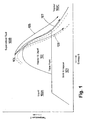
- the temperature / entropy phase diagram for carbon dioxide is shown in Fig. 1.
- This comprises a solid / vapour region 101, a vapour / liquid region 102, and a region 103 wherein the carbon dioxide passes through a continuum from liquid 103A through a supercritical fluid 103B to vapour 103C.
- expansion of the solvent e.g. in a RESS process to increase entropy causes the solvent to enter the vapour region 103C. If the solvent contains a dissolved solute then this expansion and subsequent lowering of the solvent power of the compressed fluid will cause precipitation of the solute.
- the expansion of the supercritical solution follows a pathway 105 such that the solution starts at a point 104 in the Dense Fluid Region, remains in the continuum 103, and passes directly from the supercritical phase into the vapour phase.
- Expansion of a solution in a single step whereby the solvent is initially in a supercritical state to a point where the solvent is in a vapour state involves pre-expansion temperatures which can be high enough to cause degradation of very heat sensitive solutes such as pharmaceutical compounds. It is an object of the present invention to provide at least a partial solution to this problem. Further aspects, objects and advantages of the present invention will be apparent from the following description.
- a process for the precipitation of a solid solute from a Dense Fluid Solvent is provided according to claim 1.
- the Dense Fluid Solvent should be in the process of this first aspect of the invention to achieve its effects, because in practice such phase boundaries can be ill-defined rather than sharp boundaries.
- the term "in the vapour region close to the boundary with a two phase region" used herein is intended to inter alia include points on the temperature / entropy phase diagram +10% greater in the entropy axis direction of the temperature / entropy phase diagram than the actual vapour phase - two phase boundary.
- the process of the invention includes the additional process steps of causing or allowing the residual solvent which is in part in a solid or liquid state to evaporate, and collecting the precipitated solute.
- the process of the invention appears to be suitable for use with any solute which is soluble in and not disadvantageously chemically reactive with the Dense Fluid Solvent when this is in the Dense Fluid Solvent state, e.g. in a supercritical fluid state.
- solutes may be pharmaceutical compounds e.g. drug solutes.
- the present invention is applicable for any Dense Fluid Solvent.
- suitable Dense Fluid Solvents include carbon dioxide, ethane, ethylene, propane, fluorocarbons, and water, or mixtures thereof, under appropriate physical conditions to be in a Dense Fluid Solvent, e.g. supercritical fluid state or compressible liquid state.
- the solution of the solute in the Dense Fluid Solvent may be formed by any of the known methods for forming such solutions. Typically this method may involve passing a flow of the Dense Fluid Solvent, e.g. a supercritical fluid through a column or other vessel containing the solute, thereby bringing the Dense Fluid Solvent and solute into contact to form a solution.
- the conditions, most significantly pressure and temperature are such that the first condensable fraction of solute material is a liquid phase, for example a molten solid.
- the temperature of the solution may be above the melting point, at the pressure of the solution, of a solute which is a solid. Such a temperature may easily be determined experimentally or may be found in the literature.
- the process of the invention may be operated over a range of solution concentrations of the solute in the Dense Fluid Solvent, but suitably the process may be operated with the Dense Fluid Solvent saturated with the solute. It will be understood by those skilled in the art that the solubility of solutes in Dense Fluid Solvents such as supercritical fluids is highly dependent upon the pressure of the fluid.
- the solution so formed may be expanded using methods which are known in the art, for example, expansion through an orifice downstream of which is an expansion region, e.g. the interior of an expansion vessel.
- Various devices are known which comprise such an orifice e.g. and are suitable for use in the process of this invention.
- One such device simply comprises a flat plate with a single orifice therethrough defining the restriction, and is generally known as an "Orifice Plate Nozzle".
- Variations of this type of device include a "Capillary Tube Nozzle", in which the orifice is in the form of a long thin tube (capillary) (see for example D. W. Matson et al, Ind. Eng. Chem. Res.
- the expansion of the solution in the Dense Fluid Solvent is carried out under conditions such that the solution passes from a Dense Fluid Region, into a two-phase region of its phase diagram.
- a Dense Fluid Region In terms of the phase diagram shown in Fig 1, passage from a Dense Fluid Solvent region to a two-phase vapour + liquid then a two-phase solid + vapour region is represented by pathway 106.
- Passage from a Dense Fluid Solvent region to a region in the vapour phase close to the boundary with the two-phase region which is not in accordance with the invention is represented by pathway 107.
- the pathway followed is such that the solution enters a solid / vapour region on expansion.
- the expansion of the solution in the Dense Fluid Solvent to follow such pathways through the phase diagram may preferably be achieved in the process of this invention by performing the expansion under conditions such that the solvent expands in a manner that is or approximates to an isenthalpic pathway.
- suitable conditions of temperature and pressure which define isenthalpic pathways across the phase diagram are known, and are illustrated in the literature, e.g. for carbon dioxide in Perry's "Chemical Engineer's Handbook".
- Isenthalpic pathways for such substances which follow a pathway such that the that the Dense Fluid Solvent passes from the Dense Fluid Solvent region of its phase diagram into a two-phase region of its phase diagram, or into a region of its phase diagram in the vapour region close to the boundary with a two phase region are hence known.
- Two typical isenthalpic pathways are shown by the two dotted lines ---- in Fig. 1. Many other isenthalpic pathways exist and will be apparent to those skilled in the art.
- the pathway the solution follows through the temperature/entropy phase diagram is controlled by the post-expansion pressure, i.e. the pressure in the expansion region into which the solution expands downstream of the restriction.
- the post-expansion pressure may be sub-atmospheric, atmospheric, or between atmospheric and the pressure of the Dense Fluid Solvent before expansion (i.e. the pre-expansion pressure).
- the post-expansion pressure may be less than the critical pressure (ca. 72 bar).
- a preferred post expansion pressure for carbon dioxide is in the ranges 1-50 bar, especially 1-30 bar, particularly 1-10 bar, most preferably around atmospheric pressure.
- the expansion is carried out extremely rapidly, so that as little heat as possible is transferred to the expanding solution.
- Suitably rapid expansion may for example be achieved by expansion through a 25-50 ⁇ m diameter by 25 ⁇ m long orifice of the kind discussed above.
- a plurality of orifices, or an expansion apparatus of a suitably large scale may be used to achieve an industrial scale process. Suitable ways of adapting the process of the invention to an industrial scale will be apparent to those skilled in the art, e.g. of chemical engineering.
- the former Dense Fluid Solvent is present as a vapour-liquid mixture or a solid-vapour mixture (plus the precipitated solute). Therefore the precipitated solute is isolated from the former Dense Fluid Solvent by evaporation of the former solvent.
- heat can be applied to the expansion vessel, if desired.
- the carbon dioxide is a vapour-liquid mixture
- sufficient heat may be put into the expansion vessel so as to evaporate any liquid carbon dioxide, and the precipitated solute may then be removed from the vessel.
- the solid carbon dioxide may settle out with the precipitating solute and sublime to leave the precipitated solute. This rate of sublimation can be enhanced by heating the expansion vessel.
- the process is used to modify the physical form of the solute.
- the solute may be initially in a first physical form in which form it is dissolved in the Dense Fluid Solvent, and the solute may be precipitated from solution, and subsequently isolated from the solvent, in a second physical form having different physical characteristics to the first physical form.
- This may be used to modify such physical characteristics of the solute as particle size and surface area, particle habit, porosity, crystal structure and bulk powder properties such as density and flowability.
- the process of the invention may advantageously be used to convert the solute from a first physical form of low particle surface area into a second physical form of higher surface area, from a first physical form such as needle shaped crystals which are susceptible to "matting" with poor bulk flow properties, into a second physical form of more isometric or more spherical crystals of higher bulk density and/or with better bulk flow properties, or from particles of low porosity to a form of increased porosity.
- Such modifications of the physical form are of benefit in bulk powder processing for example in the manufacture of pharmaceutical dosage forms.
- a further advantage of the process of the invention may be observed in that the extent of degradation of sensitive solutes such as drug compounds may be reduced relative to known RESS processes in which expansion of the solution directly into the vapour phase, without entering a two-phase region, occurs.
- two or more solutes may be formed into solution in the Dense Fluid Solvent, for example to form a mixed precipitated product.
- the solution may comprise a mixture of two or more Dense Fluid Solvents, or a mixture of one or more Dense Fluid Solvents with one or more liquid co-solvents or entrainers.
- the solution may include non-dissolved particles, or the expansion vessel may contain particles e.g. in the form of a cloud, so that on expansion a matrix of the particles and the precipitated solute is formed, or the particles become coated by the precipitated solute, or the precipitated solute becomes coated by the particles.
- the process of the invention may be operated as a batch process, or as a continuous or semicontinuous process.
- An apparatus for carrying out the process of this invention may comprise:
- Such an apparatus further incorporating a novel pressure-relief valve has been devised which is particularly effective in use with the process of the present invention, but also with other processes using a Dense Fluid Solvent for the processing of a substance, for example a substance which can dissolve, i.e. is a solute in the Dense Fluid Solvent.
- This novel pressure-relief valve has a body, an inlet for said solution, an outlet, a flow passage defined by an inner surface of said body extending between said inlet and outlet, a pressure-relief orifice located within said flow passage, and means for varying the effective flow area of the orifice, wherein the orifice and outlet are mutually disposed such that the orifice faces the outlet and from each point in the effective flow area of the orifice, there is a substantially uninterrupted linear flow path through the outlet.
- the outlet of the pressure-relief valve extends downwardly away from the pressure-relief orifice. More preferably the outlet is flared such that its effective flow area increases away from the orifice.
- any accretion of substance, especially solids, which does occur in the outlet is less likely to block the outlet. Accretion is most likely to be problematic when the substance being processed is a solid when it separates (precipitates) from solution.
- the pressure-relief valve may be provided with at least one additional inlet in the outlet of the body.
- additional inlet(s) may be used to feed additional substances, e.g. additional reagents, solvents, particles etc. into the outlet stream, or a purge fluid (preferably gas) into the outlet to dislodge any accreted substance.
- the pressure-relief valve may be provided with a valve stem and a valve seat, the valve stem being aligned with the outlet, so that the pressure-relief orifice is defined therebetween, and the valve stem and valve seat being moveable relative to each other so defining the means for varying the effective flow area of the pressure relief valve.
- the valve stem may be reciprocated, suitably rapidly, relative to the orifice to generate shock waves in the flow path thereby to dislodge any accreted substance.
- the apparatus also includes temperature control means.
- temperature control means are located such that the temperature of the Dense Fluid Solvent may be varied both before and after dissolution of the solute, and after passing through the expansion device.
- the dissolving means comprises an extraction vessel.
- the solute to be processed is provided, e.g. deposited in the extraction vessel and Dense Fluid Solvent is passed therethrough, so dissolving the solute.
- the expansion device comprises a restriction in the flow path, such as a capillary or orifice type nozzle.
- the process of this aspect of the invention is suitable for use with any Dense Fluid Solvent, for example as discussed above.
- the Dense Fluid Solvent e.g. carbon dioxide
- the Dense Fluid Solvent may be in several states immediately after expansion, e.g. after the rapid pressure drop, depending upon the pre-expansion pressure and temperature and the post-expansion pressure and temperature.
- the former Dense Fluid Solvent may be a gas, e.g. a gas in the vapour region close to the boundary with a two phase region. When it is a gas the majority of the condensing substance may be separated simply by allowing it to settle in the expansion chamber, and any final traces of the substance may be separated by scrubbing the gas with a filter.
- the process of this aspect of the invention may therefore be a RESS type process.
- the former Dense Fluid Solvent can be a two-phase mixture, for example a vapour-liquid mixture or a vapour-solid mixture, in which case the process can be a process of the first aspect of this invention.
- the substance is a solid solute, although the process of this aspect of the invention may be suitable for semisolid (e.g. waxy), or liquid (low or high viscosity) solutes.
- the conditions, most significantly pressure and temperature, are such that the first condensable fraction of solute material is a liquid phase, for example a molten solid.
- the present invention is not to be limited by any particular theory as to how solid particles of a substance, e.g. a solute, are formed, but it is believed that RESS and PGSS type processes occur.
- a solute is a solid in a molten state
- expansion of the solution may result in condensation of material which comprises small droplets of the molten solute containing the Dense Fluid Solvent.
- Dense Fluid Solvent transforms to a gas PGSS type processes may atomise these droplets.
- the equipment consists of a solvent delivery section, an extraction section and a precipitation section.
- the equipment can be used for solubility measurement, RESS to ambient pressure and RESS to elevated pressures.
- Carbon dioxide (BOCTM Chemically Pure grade) is withdrawn as a liquid from the supply cylinder 201, passed through refrigeration unit 202 and brought to the desired pressure by pump 203.
- the high pressure carbon dioxide stream is heated to the required temperature in heater 204 (6mm O.D. x 3m coil which is inside an air bath 205).
- Vessel 206 (0.51 internal volume) is loaded with 40g of solute, and carbon dioxide as above is delivered to the vessel 206 via flow path 207. The carbon dioxide passes through vessel 206, dissolves the solute and thus forms the Dense Fluid solution.
- Precipitating Section The so-formed solution then flows along flow path 208 toward an expansion region being vessel 209.
- the solution is then expanded to a pressure lower than that of extraction through an expansion device 210.
- an orifice plate nozzle of diameter 50 ⁇ m and length 50 ⁇ m was used.
- Solution temperatures could be regulated prior to expansion (i.e. the pre-expansion temperature) using heat exchanger 211, which is a fluid jacket or other suitable heat transfer device around the flow path pipework between vessel 206 and the entrance to expansion vessel 209.
- the pressure inside the vessel 209 and the pre-expansion temperature are controlled so as to cause the expanding dense fluid solvent to enter a region where it becomes a vapour/liquid mixture or a solid/vapour mixture according to the expansion path 106 shown in Fig. 1.
- the solution expands precipitation of the dissolved solute takes place, and the solute settles out in vessel 209.
- the precipitating solute can be collected in a separator 212.
- a hot gas e.g. in this case carbon dioxide can be passed into vessel 209 from storage vessel 213 through heat exchanger 214. This will control the background temperature into which the fluid is expanding. Additional temperature control can be applied to the expansion vessel 209 by other means such as a heating jacket (not shown).
- Denbufylline supplied by SmithKline Beecham plc. As supplied this compound was in the form of needle shaped crystals.
- the pre-expansion temperature was reduced so that the Denbufylline solution was expanded into the two-phase vapour + liquid region or the solid + vapour region , according to the process of this invention.
- the observed outcome of this modification was that the particle size, particle habit, porosity, crystal structure and bulk properties were all dramatically affected by the pressure to which the solution was expanded, i.e. the post expansion pressure.
- the post expansion pressures used in the RESS studies were either atmospheric pressure or elevated pressures in the range 10 - 30 bar gas pressure, i.e. looking specifically at 10, 20 and 30 bar gas pressure.
- the particle size of the powders produced were characterised by specific surface area measurement. It was found that the specific surface area of the powders produced had a dependency on the post expansion pressure.
- Denbufylline was produced by RESS in two main forms, an isometric form and an acicular or fibrous form. Generally speaking it was found that when the supercritical solution was expanded to atmospheric pressure the most isometric form as the dominant habit of the particles was obtained. When the solution was expanded to elevated pressures (say 10-30 bar gas pressure) the acicular or fibrous form was obtained as the dominant habit. Therefore it would seem that the habit can be controlled using the post expansion pressure.
- Porosity measurements were carried out on some selected samples of both the isometric and acicular material produced by RESS and the original Denbufylline.
- the porosity measurements made on these selected samples showed that material formed by RESS to elevated pressures (the acicular material) is not very porous (very like the starting material) and any pores are in the size range 10-25 Angstroms.
- the material formed by RESS to atmospheric pressure had a continuous range of pore sizes ranging from 10-300 Angstroms.
- the powder product When the solution was expanded to elevated pressures (10-30 bar gas pressure) the powder product had a very low bulk density, a " woolly" appearance and very poor flow properties.
- the powder On expansion atmospheric pressure it was found that the powder had a relatively large bulk density (at least six times as large as that material produced at elevated pressures), a granular appearance and good flow properties when compared to the starting material and material produced at elevated pressures.
- These bulk properties could be related to the habit of the material making up the powder.
- the post expansion pressure can be used to control bulk powder properties.
- the Hausner ratio of both original Denbufylline as supplied and Denbufylline treated by the RESS process of the invention as described above was measured.
- the Hausner ratio of Denbufylline as supplied was 2.05, and for all RESS-processed material prepared using the process of the invention was lower than this, being in the range 1.47 - 1.85. This indicates an increase in the granularity of the powder.
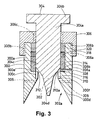
- a pressure-relief valve comprises a cylindrical body 300 having a passage 302 extending therethrough, a valve stem 304 axially and rotatably moveable in the passage 302 and a retaining nut 306.
- the body 300 has a first annular portion 300a with an externally screw-threaded region 300b, a second annular portion 300c and an internally flared portion 300d, all of unitary construction.
- the first annular portion 300a is connected to the second annular portion 300c by an inwardly stepped region, so forming a first annular surface 300e.
- an inwardly extending lip forms a second annular surface 300f.
- the portion 300d defines a frusto-conically flared outlet 302a of the valve.
- a first flow passage 308a extends through the second annular portion 300a and defines a part of a valve inlet 308, and a pair of additional flow passages 309 extend through the portion 300d into the outlet 302a of the valve.
- a cylindrical region 304a of the valve stem 304 is externally screw-threaded over part of its length and has a manual control knob 304b at its outer end.
- the manual control knob may be replaced by a pneumatic or electrical controller such as is commonly used to control other types of valves.
- the valve stem 304 has a first and second frusto-conical tapering regions 304c and 304d at its inner end.
- the valve stem 304 is positioned in the passage 302 though the valve body 300 such that the tapered end 304d of the valve stem 304 is located in the outlet 302a of the valve.
- annular seat 310 which rests on the second annular surface 300f of the body 300 and is a close fit within the annular region 300c of the body 300.
- the inner diameter of the annular seat 310 corresponds to the minimum diameter of the outlet 302a, so that no part of the annular surface 300f projects into the flowpath. It should be noted that, in use, a gap which defines an expansion or pressure-relief annular orifice 312 will be maintained between a sealing edge 310a of the seat 310 and the region 304c of the valve stem 304. As a result of the positioning of the seat 310 relative to the region 300d of the body 300, there exists an uninterrupted linear flowpath from each point in the orifice 312 though the seat 310 into the outlet 302a.
- valve stem 304 Correct positioning of the valve stem 304 is facilitated by an annular guide 314 which is seated on the first annular surface 300e of the valve body 300.
- the guide 314 has a flow passage 308b therethrough which is aligned with the first flow passage 308a so forming part of the valve inlet 308.
- a flow chamber 316 is defined between the valve stem 304, annular seat 310 and guide 314. It should be noted that the effective flow area of the inlet 308 is sufficiently large such that, in use, a significant pressure drop (and hence premature separation of substance from solution) does not occur as fluid enters the flow chamber 316.
- the sealing edge 31 0a of the seat 310 may be chamfered so that, in use, accretion of solid substance in the flow chamber 316 is less likely.
- the retaining nut 306 has a first internally screw-threaded region 306a which engages with the screw-threaded region 300b of the body 300 so that a lower surface 306b of the nut 306 abuts the seal backing ring 320, and a second internally screw-threaded region 306c which engages with the screw-threaded region of the valve stem 304.
- a solution of a solid solute in a Dense Fluid Solvent such as supercritical carbon dioxide enters the valve through the valve inlet 308 and passes into the flow chamber 316. From there it passes through the orifice 312 where it is rapidly expanded such that the solute separates from the solution in the outlet 302a to form small crystals.
- the rate of flow through the valve is adjusted manually (or mechanically in the case where a controller is provided as mentioned hereinbefore) by appropriate rotation of the knob 304b to effect axial adjustment of the region 304c relative to the valve seat 310.
- Accretion of solid product on the valve stem 304 or body 300 downstream of the orifice 312 can be removed by injecting pulses of pressurized gas e.g.
- the temperature of the gas passing through the additional flow passages 309 may be controlled.
- another gas such as nitrogen or even compressed air may be employed for this purpose.
- the gas introduced through the flow passages 309 may be heated to enable the temperature within for example a downstream expansion vessel (not shown in Fig. 3) to be controlled to assist in evaporating any liquefied gas resulting from expansion of the former Dense Fluid Solvent, e.g. carbon dioxide, or in subliming any solidified gas which may form as a result of expansion.
- the additional flow passages 309 may be used to supply material dissolved or suspended in a fluid such that the material is deposited on the substance being processed.
- the apparatus described above can be used to purify substances at a high concentration and flow rate, maintaining a steady flow even under unpredictable non-ideal flow conditions, without blockage of the valve.
- a flowpath 402 extends from a carbon dioxide storage cylinder 404 successively through a refrigeration unit 406, a compressor pump 408, a heat exchanger 410, an extraction vessel 412, a second heat exchanger 414, an expansion vessel 416 fitted with a pressure-relief valve 418, being a pressure relief valve as shown in and described above with reference to Fig. 3, a filter 420 and a flow meter 422.
- a second flow path 424 bypasses the extraction vessel 412.
- a purge gas supply line 426 is connected with the pressure-relief valve 418.
- At various locations along the flow paths 402, 424 and 426 are located control valves 428a, 428b and 428c respectively.
- carbon dioxide maintained at 50 bar is withdrawn from the storage cylinder 404 and liquefied by cooling to between -4 and +4°C in the refrigeration unit 406.
- the resultant liquid carbon dioxide is compressed to the desired system operating pressure (typically 60 to 350 bar) by the pump 408 and brought to the system operating temperature by passing through the heat exchanger 410.
- the carbon dioxide is passed upwardly through the extraction vessel 412 which contains a solute substance in a packed bed, resulting in dissolution of the solute in the carbon dioxide.
- the concentration of the solution may be reduced by diluting with fresh liquid carbon dioxide via flow path 424, by appropriate setting of the valves 428a and 428b.
- the second heat exchanger 414 brings the solution to the required temperature, before being passed through the pressure-relief valve 418.
- the drop in pressure in the pressure relief valve results in rapid expansion of the carbon dioxide e.g. from 150 bar gas pressure upstream of the pressure relief valve to ca. 1 bar atmosphere pressure in the expansion vessel 416.
- the purge gas supply line 426 feeds gaseous carbon dioxide from a reservoir at a pressure of for example 150 bar gas pressure under the control of the valve 428c, to the pressure-relief valve 418.
- the control valve 428c allows the carbon dioxide to expand to the pressure of the expansion vessel 416 whatever pressure drop occurs in the pipework between the valve 428c and the valve 418.
- the solvating power of the carbon dioxide is reduced and substances dissolved therein precipitate as small crystals of substantially uniform size. Separation is easily achieved because the solid product settles in the expansion vessel 416 and the now gaseous carbon dioxide passes out of the expansion vessel 416 to be scrubbed by the filter 420. Under these rapid expansion conditions, some solid carbon dioxide may be formed but, if it does, then it rapidly sublimes.
- the flow rate of the gaseous carbon dioxide is measured by the flow meter 422 to facilitate overall control of the process, and is vented to the atmosphere, as shown, it is also possible, however, for the carbon dioxide to be continuously recycled back to the start of the process.
Claims (14)
- Procédé pour la précipitation d'un soluté solide à partir d'un solvant fluide dense, comprenant les étapes consistant :à former une solution du soluté dans le solvant fluide dense ;puis à provoquer l'expansion de la solution ainsi formée dans des conditions telles que le solvant fluide dense passe de la région de solvant fluide dense (103B) de son diagramme de phases dans une région de solide + vapeur ou liquide + vapeur (101, 102) de son diagramme de phases, la précipitation du soluté à partir de la solution se produisant tandis que le solvant est dans la région de solide + vapeur ou liquide + vapeur,puis à isoler le soluté solide précipité en provoquant l'évaporation du solvant en une vapeur.
- Procédé suivant la revendication 1, caractérisé en ce que le solvant fluide dense est choisi entre le dioxyde de carbone, l'éthane, l'éthylène, le propane, des hydrocarbures fluorés et l'eau, dans des conditions physiques appropriées pour être à l'état de fluide surcritique.
- Procédé suivant l'une quelconque des revendications 1 et 2, caractérisé en ce que les conditions dans lesquelles l'expansion de la solution est effectuée sont telles que la première fraction condensable de matière de soluté soit le soluté à l'état fondu.
- Procédé suivant la revendication 3, caractérisé en ce que la température de la solution est supérieure au point de fusion du soluté à la pression de la solution.
- Procédé suivant l'une quelconque des revendications 1 à 4, caractérisé en ce que la solution pénètre dans une région de solide + vapeur (101) lors de son expansion.
- Procédé suivant l'une quelconque des revendications précédentes, caractérisé par l'expansion de la solution dans des conditions telles que le solvant subisse une expansion d'une manière qui correspond à une, ou est proche d'une, voie isenthalpique.
- Procédé suivant l'une quelconque des revendications précédentes, caractérisé en ce que la voie que suit la solution à travers le diagramme de phases température/entropie du solvant fluide dense est commandée par la pression de post-expansion.
- Procédé suivant la revendication 7, caractérisé en ce que le solvant fluide dense est le dioxyde de carbone et la pression de post-expansion est comprise dans l'intervalle de 1 à 50 bars.
- Procédé pour la modification de la forme physique d'un soluté, dans lequel le soluté est initialement sous une première forme physique et est soumis sous cette première forme au procédé suivant l'une quelconque des revendications précédentes et est finalement sous une seconde forme physique.
- Appareil pour la mise en oeuvre d'un procédé suivant la revendication 1, comprenant un moyen (408) pour la mise sous pression d'un solvant fluide dense ; un moyen (412) pour la dissolution du soluté dans le solvant fluide dense de manière à former une solution ; un trajet d'écoulement entre ledit moyen de mise sous pression (408) et ledit moyen de dissolution (412) ; un dispositif d'expansion (418) à travers lequel la solution peut passer et peut subir une expansion du côté aval du dispositif ; un trajet d'écoulement entre ledit moyen de dissolution et le dispositif d'expansion ; un récipient d'expansion (416) qui renferme une région d'expansion dans laquelle la solution peut passer, la région d'expansion étant en aval du dispositif d'expansion (418), dans lequelle dispositif d'expansion (418) comprend une soupape de libération de pression (418) ayant un corps (300), un orifice d'admission (308) pour ladite solution, un orifice de sortie (302a), un passage d'écoulement (308a) défini par une surface intérieure dudit corps (300) s'étendant entre l'orifice d'admission (308) et l'orifice de sortie (302a), un orifice de libération de pression (312) situé dans ledit passage d'écoulement (308a) et un moyen (304b) pour faire varier la surface d'écoulement efficace de l'orifice (312), l'orifice (312) et l'orifice de sortie (302a) étant disposés mutuellement de telle sorte que l'orifice (312) soit face à l'orifice de sortie (302a) et, à partir de chaque point dans la surface efficace d'écoulement de l'orifice (312), il existe un trajet d'écoulement linéaire pratiquement ininterrompu à travers l'orifice de sortie (302a).
- Appareil suivant la revendication 10, caractérisé en ce que l'orifice de sortie (302a) de la soupape de libération de pression (418) est évasé de telle sorte que sa surface d'écoulement efficace augmente à distance de l'orifice (312).
- Appareil suivant la revendication 10 ou 11, caractérisé en ce que la soupape de libération de pression (418) est munie d'au moins un orifice d'admission supplémentaire (309) dans l'orifice de sortie (302a) du corps (300).
- Appareil suivant l'une quelconque des revendications 10 à 12, caractérisé en ce que la soupape de libération de pression (418) est munie d'une tige de soupape (304) et d'un siège de soupape (310), la tige de soupape étant alignée avec l'orifice de sortie (302a), de telle sorte que l'orifice de libération de pression (312) soit défini entre eux, et la tige de soupape (304) et le siège de soupape (310) étant mobiles l'un par rapport à l'autre de manière à définir le moyen pour faire varier la surface d'écoulement efficace de la soupape de libération de pression (418).
- Appareil suivant la revendication 13, caractérisé en ce que la tige de soupape (304) peut être soumise à un mouvement alternatif par rapport à l'orifice (312) pour engendrer des ondes de choc dans le trajet d'écoulement, en délogeant ainsi toute substance présentant une accrétion.
Applications Claiming Priority (5)
| Application Number | Priority Date | Filing Date | Title |
|---|---|---|---|
| GB9712945 | 1997-06-20 | ||
| GBGB9712945.6A GB9712945D0 (en) | 1997-06-20 | 1997-06-20 | Apparatus and method for processing a substance |
| GBGB9717344.7A GB9717344D0 (en) | 1997-08-16 | 1997-08-16 | Process |
| GB9717344 | 1997-08-16 | ||
| PCT/GB1998/001800 WO1998058722A1 (fr) | 1997-06-20 | 1998-06-19 | Traitement d'une substance par un fluide dense (par exemple, un fluide supercritique) |
Publications (2)
| Publication Number | Publication Date |
|---|---|
| EP0991455A1 EP0991455A1 (fr) | 2000-04-12 |
| EP0991455B1 true EP0991455B1 (fr) | 2004-11-24 |
Family
ID=26311757
Family Applications (1)
| Application Number | Title | Priority Date | Filing Date |
|---|---|---|---|
| EP98930901A Expired - Lifetime EP0991455B1 (fr) | 1997-06-20 | 1998-06-19 | Traitement d'une substance par un fluide dense (par exemple, un fluide supercritique) |
Country Status (7)
| Country | Link |
|---|---|
| EP (1) | EP0991455B1 (fr) |
| JP (1) | JP4616945B2 (fr) |
| AU (1) | AU8118298A (fr) |
| CA (1) | CA2294367A1 (fr) |
| DE (1) | DE69827794T2 (fr) |
| ES (1) | ES2234125T3 (fr) |
| WO (1) | WO1998058722A1 (fr) |
Families Citing this family (8)
| Publication number | Priority date | Publication date | Assignee | Title |
|---|---|---|---|---|
| JP4874483B2 (ja) | 1999-06-09 | 2012-02-15 | ロバート イー. シーバース | 超臨界流体補助ネブライゼーション及びバブル乾燥 |
| GB9927011D0 (en) * | 1999-11-16 | 2000-01-12 | Advanced Phytonics Ltd | Method for the production of particles |
| EP1263516A1 (fr) * | 2000-03-03 | 2002-12-11 | Boehringer Ingelheim Pharmaceuticals Inc. | Traitement de matiere par cycles repetes d'expansion et contraction du solvant |
| JP3435158B1 (ja) * | 2001-08-10 | 2003-08-11 | 花王株式会社 | 複合化粒子の製造法 |
| FR2874836B1 (fr) * | 2004-09-09 | 2007-04-27 | Pierre Fabre Medicament Sa | Procede d'enrobage de poudres |
| JP5000095B2 (ja) * | 2005-03-11 | 2012-08-15 | 花王株式会社 | 有機結晶粒子の製造方法 |
| WO2007009164A1 (fr) | 2005-07-15 | 2007-01-25 | Eiffel Technologies Limited | Procede de formation de particules |
| FI20140266A (fi) | 2014-10-06 | 2016-04-07 | Nanoform Finland Oy | Menetelmä ja laite nanopartikkeleiden valmistamiseksi |
Family Cites Families (6)
| Publication number | Priority date | Publication date | Assignee | Title |
|---|---|---|---|---|
| US4734451A (en) * | 1983-09-01 | 1988-03-29 | Battelle Memorial Institute | Supercritical fluid molecular spray thin films and fine powders |
| US4770780A (en) * | 1984-04-25 | 1988-09-13 | Cf Systems Corporation | Liquid CO2 /cosolvent extraction |
| US5011819A (en) * | 1988-06-02 | 1991-04-30 | Hewlett-Packard Company | Process using supercritical conditions for producing highly accurate and homogeneous powder mixture useful in fabrication of high quality ceramic superconductors |
| EP0384969B1 (fr) * | 1989-02-27 | 1993-08-25 | Hewlett-Packard Company | Dispositif de piégeage avec valve à déplacement axial |
| JPH0557166A (ja) * | 1991-08-31 | 1993-03-09 | Kobe Steel Ltd | 被覆微粒子の製造方法 |
| GB9413875D0 (en) * | 1994-07-09 | 1994-08-31 | British Nuclear Fuels Plc | Separating solutes from solutions |
-
1998
- 1998-06-19 DE DE69827794T patent/DE69827794T2/de not_active Expired - Lifetime
- 1998-06-19 WO PCT/GB1998/001800 patent/WO1998058722A1/fr active IP Right Grant
- 1998-06-19 CA CA002294367A patent/CA2294367A1/fr not_active Abandoned
- 1998-06-19 ES ES98930901T patent/ES2234125T3/es not_active Expired - Lifetime
- 1998-06-19 EP EP98930901A patent/EP0991455B1/fr not_active Expired - Lifetime
- 1998-06-19 AU AU81182/98A patent/AU8118298A/en not_active Abandoned
- 1998-06-19 JP JP50399399A patent/JP4616945B2/ja not_active Expired - Fee Related
Also Published As
| Publication number | Publication date |
|---|---|
| JP4616945B2 (ja) | 2011-01-19 |
| JP2002505617A (ja) | 2002-02-19 |
| AU8118298A (en) | 1999-01-04 |
| CA2294367A1 (fr) | 1998-12-30 |
| EP0991455A1 (fr) | 2000-04-12 |
| ES2234125T3 (es) | 2005-06-16 |
| WO1998058722A1 (fr) | 1998-12-30 |
| DE69827794T2 (de) | 2005-12-22 |
| DE69827794D1 (de) | 2004-12-30 |
Similar Documents
| Publication | Publication Date | Title |
|---|---|---|
| US5851453A (en) | Method and apparatus for the formation of particles | |
| Huang et al. | Formation of ultrafine aspirin particles through rapid expansion of supercritical solutions (RESS) | |
| RU2136655C1 (ru) | Сальметерол ксинафоат с регулируемым размером частиц и фармацевтический состав | |
| Bristow et al. | Analysis of the supersaturation and precipitation process with supercritical CO2 | |
| CA2192811C (fr) | Procede et dispositif de formation de particules | |
| EP1077760B1 (fr) | Procedes et appareil pour la formation de particules | |
| US6830714B1 (en) | Process and apparatus for producing particles using a supercritical fluid | |
| EP0991455B1 (fr) | Traitement d'une substance par un fluide dense (par exemple, un fluide supercritique) | |
| Kröber et al. | Materials processing with supercritical antisolvent precipitation: process parameters and morphology of tartaric acid | |
| Foster et al. | Application of dense gas techniques for the production of fine particles | |
| EP1401563B1 (fr) | Procede de production de microparticules et/ou nanoparticules | |
| Reverchon et al. | Griseofulvin micronization and dissolution rate improvement by supercritical assisted atomization | |
| WO2004110603A2 (fr) | Procede de preparation de particules a partir d'emulsions de solution dans un fluide supercritique ou un gaz comprime | |
| KR100755734B1 (ko) | 용매의 반복적인 팽창-수축에 의한 물질의 가공방법 | |
| JPH0557166A (ja) | 被覆微粒子の製造方法 | |
| JP7251817B2 (ja) | ナノ粒子を生成するプロセス | |
| JPH03271113A (ja) | 微粒の製造方法 | |
| Kröber et al. | Micronization of organic materials by crystallization with compressed gases | |
| WO2007072072A2 (fr) | Appareil de cristallisation et processus avec fluide surcritique | |
| Sugiyama et al. | Nanoparticle Formation of Yellow Pigment by ASES Process using Supercritical CO2 | |
| Bolten et al. | NOVEL MATERIALS FOR CONTROLLED RELEASE (CPD) | |
| GB2339165A (en) | Method and apparatus for particle formation using supercritical fluids |
Legal Events
| Date | Code | Title | Description |
|---|---|---|---|
| PUAI | Public reference made under article 153(3) epc to a published international application that has entered the european phase |
Free format text: ORIGINAL CODE: 0009012 |
|
| 17P | Request for examination filed |
Effective date: 19991129 |
|
| AK | Designated contracting states |
Kind code of ref document: A1 Designated state(s): BE CH DE ES FR GB IT LI NL |
|
| 17Q | First examination report despatched |
Effective date: 20010629 |
|
| RAP1 | Party data changed (applicant data changed or rights of an application transferred) |
Owner name: THE UNIVERSITY OF BIRMINGHAM Owner name: SMITHKLINE BEECHAM PLC |
|
| GRAP | Despatch of communication of intention to grant a patent |
Free format text: ORIGINAL CODE: EPIDOSNIGR1 |
|
| GRAS | Grant fee paid |
Free format text: ORIGINAL CODE: EPIDOSNIGR3 |
|
| GRAA | (expected) grant |
Free format text: ORIGINAL CODE: 0009210 |
|
| AK | Designated contracting states |
Kind code of ref document: B1 Designated state(s): BE CH DE ES FR GB IT LI NL |
|
| PG25 | Lapsed in a contracting state [announced via postgrant information from national office to epo] |
Ref country code: LI Free format text: LAPSE BECAUSE OF FAILURE TO SUBMIT A TRANSLATION OF THE DESCRIPTION OR TO PAY THE FEE WITHIN THE PRESCRIBED TIME-LIMIT Effective date: 20041124 Ref country code: CH Free format text: LAPSE BECAUSE OF FAILURE TO SUBMIT A TRANSLATION OF THE DESCRIPTION OR TO PAY THE FEE WITHIN THE PRESCRIBED TIME-LIMIT Effective date: 20041124 |
|
| REG | Reference to a national code |
Ref country code: GB Ref legal event code: FG4D |
|
| REG | Reference to a national code |
Ref country code: CH Ref legal event code: EP |
|
| REF | Corresponds to: |
Ref document number: 69827794 Country of ref document: DE Date of ref document: 20041230 Kind code of ref document: P |
|
| REG | Reference to a national code |
Ref country code: CH Ref legal event code: PL |
|
| REG | Reference to a national code |
Ref country code: ES Ref legal event code: FG2A Ref document number: 2234125 Country of ref document: ES Kind code of ref document: T3 |
|
| PLBE | No opposition filed within time limit |
Free format text: ORIGINAL CODE: 0009261 |
|
| STAA | Information on the status of an ep patent application or granted ep patent |
Free format text: STATUS: NO OPPOSITION FILED WITHIN TIME LIMIT |
|
| ET | Fr: translation filed | ||
| 26N | No opposition filed |
Effective date: 20050825 |
|
| REG | Reference to a national code |
Ref country code: FR Ref legal event code: PLFP Year of fee payment: 19 |
|
| PGFP | Annual fee paid to national office [announced via postgrant information from national office to epo] |
Ref country code: GB Payment date: 20160525 Year of fee payment: 19 Ref country code: ES Payment date: 20160607 Year of fee payment: 19 |
|
| PGFP | Annual fee paid to national office [announced via postgrant information from national office to epo] |
Ref country code: NL Payment date: 20160607 Year of fee payment: 19 Ref country code: IT Payment date: 20160610 Year of fee payment: 19 Ref country code: BE Payment date: 20160614 Year of fee payment: 19 Ref country code: FR Payment date: 20160531 Year of fee payment: 19 |
|
| PGFP | Annual fee paid to national office [announced via postgrant information from national office to epo] |
Ref country code: DE Payment date: 20160629 Year of fee payment: 19 |
|
| REG | Reference to a national code |
Ref country code: DE Ref legal event code: R119 Ref document number: 69827794 Country of ref document: DE |
|
| REG | Reference to a national code |
Ref country code: NL Ref legal event code: MM Effective date: 20170701 |
|
| GBPC | Gb: european patent ceased through non-payment of renewal fee |
Effective date: 20170619 |
|
| PG25 | Lapsed in a contracting state [announced via postgrant information from national office to epo] |
Ref country code: NL Free format text: LAPSE BECAUSE OF NON-PAYMENT OF DUE FEES Effective date: 20170701 |
|
| REG | Reference to a national code |
Ref country code: FR Ref legal event code: ST Effective date: 20180228 |
|
| PG25 | Lapsed in a contracting state [announced via postgrant information from national office to epo] |
Ref country code: DE Free format text: LAPSE BECAUSE OF NON-PAYMENT OF DUE FEES Effective date: 20180103 Ref country code: GB Free format text: LAPSE BECAUSE OF NON-PAYMENT OF DUE FEES Effective date: 20170619 |
|
| PG25 | Lapsed in a contracting state [announced via postgrant information from national office to epo] |
Ref country code: IT Free format text: LAPSE BECAUSE OF NON-PAYMENT OF DUE FEES Effective date: 20170619 Ref country code: FR Free format text: LAPSE BECAUSE OF NON-PAYMENT OF DUE FEES Effective date: 20170630 |
|
| REG | Reference to a national code |
Ref country code: BE Ref legal event code: MM Effective date: 20170630 |
|
| PG25 | Lapsed in a contracting state [announced via postgrant information from national office to epo] |
Ref country code: BE Free format text: LAPSE BECAUSE OF NON-PAYMENT OF DUE FEES Effective date: 20170630 |
|
| REG | Reference to a national code |
Ref country code: ES Ref legal event code: FD2A Effective date: 20181105 |
|
| PG25 | Lapsed in a contracting state [announced via postgrant information from national office to epo] |
Ref country code: ES Free format text: LAPSE BECAUSE OF NON-PAYMENT OF DUE FEES Effective date: 20170620 |