EP0990810A1 - Bellows-type cover member - Google Patents
Bellows-type cover member Download PDFInfo
- Publication number
- EP0990810A1 EP0990810A1 EP98118715A EP98118715A EP0990810A1 EP 0990810 A1 EP0990810 A1 EP 0990810A1 EP 98118715 A EP98118715 A EP 98118715A EP 98118715 A EP98118715 A EP 98118715A EP 0990810 A1 EP0990810 A1 EP 0990810A1
- Authority
- EP
- European Patent Office
- Prior art keywords
- bellows
- type cover
- clamping member
- cover member
- retaining
- Prior art date
- Legal status (The legal status is an assumption and is not a legal conclusion. Google has not performed a legal analysis and makes no representation as to the accuracy of the status listed.)
- Granted
Links
Images


Classifications
-
- F—MECHANICAL ENGINEERING; LIGHTING; HEATING; WEAPONS; BLASTING
- F16—ENGINEERING ELEMENTS AND UNITS; GENERAL MEASURES FOR PRODUCING AND MAINTAINING EFFECTIVE FUNCTIONING OF MACHINES OR INSTALLATIONS; THERMAL INSULATION IN GENERAL
- F16J—PISTONS; CYLINDERS; SEALINGS
- F16J3/00—Diaphragms; Bellows; Bellows pistons
- F16J3/04—Bellows
- F16J3/041—Non-metallic bellows
- F16J3/042—Fastening details
-
- F—MECHANICAL ENGINEERING; LIGHTING; HEATING; WEAPONS; BLASTING
- F16—ENGINEERING ELEMENTS AND UNITS; GENERAL MEASURES FOR PRODUCING AND MAINTAINING EFFECTIVE FUNCTIONING OF MACHINES OR INSTALLATIONS; THERMAL INSULATION IN GENERAL
- F16D—COUPLINGS FOR TRANSMITTING ROTATION; CLUTCHES; BRAKES
- F16D3/00—Yielding couplings, i.e. with means permitting movement between the connected parts during the drive
- F16D3/84—Shrouds, e.g. casings, covers; Sealing means specially adapted therefor
- F16D3/843—Shrouds, e.g. casings, covers; Sealing means specially adapted therefor enclosed covers
- F16D3/845—Shrouds, e.g. casings, covers; Sealing means specially adapted therefor enclosed covers allowing relative movement of joint parts due to the flexing of the cover
Definitions
- the invention relates to a bellows-type cover made from elastic material, such as rubber or plastic material, used, for instance, for the protection of universal joints and drive shafts in which a clamping member or members such as hose clamps or shrinkable compression rings are integrated with the bellows-type cover.
- bellows-type covers usually of accordion-like construction, such as axle boots for universal joints or for drive shafts, must be carefully sealed to protect the lubricant.
- Such bellows-type covers have been used extensively in the automotive industry, for example to protect joints at a drive shaft. They are normally fastened to the axle stub shafts by means of hose clamps or shrinkable compression rings.
- the manufacturers desire a product in which the clamping members are already integrated at or in the bellows-type covers which favours the automatic assembly of the universal joint or drive shafts in that the bellows-type covers provided with integrated clamping members are available as pre-assembled parts so as to avoid the need for mounting the clamping members on the bellows-type covers only at the final assembly as is the case today.
- a clamping member to be integrated into the bellows-type cover which consist of (1) the clamping member vulcanised into the bellows-type cover or (2) a self-holding arrangement for a clamping member adapted to be mounted on the bellows-type cover.
- the first solution involving the clamping member vulcanised into the bellows-type cover can be disregarded because such an arrangement is practically not feasible with the usual hose clamps presently used as clamping members as also with compression rings used as clamping members.
- Patent 4,299,012 which has been used extensively with axle boots in the automotive industry, if vulcanised into the bellows-type cover, would present great difficulty of being tightened by deforming the "Oetiker" ear.
- the vulcanised-in solution is also unacceptable because of substantial increase in costs.
- a shrinkable compression ring, vulcanised into the bellows-type cover can no longer be shrunk by means of the presently available tools because these tools are designed to engage during the shrinking operation with the external surface of the compression ring having a predetermined diameter in a form-locking manner in order to reduce the compression ring in its diametric dimension by the application of radial forces.
- vulcanising-in of the clamping members into the bellows-type covers provides a corrosion protection of the integrated hose clamps or compression rings because these problems can be readily avoided in the present invention by the use of appropriate materials for the clamping devices, such as stainless steel or aluminum.
- a vulcanising-in of the clamping members precludes any visual control provided at the clamping member in the installed condition insofar as correct positioning and seating of the clamping member and proper tightening of the clamping member are concerned.
- hose clamps used with drive or universal joint shafts have served extensively as information carriers in that dates such as assembly dates or other relevant dates of interest to the manufacturer were integrated into the clamping devices, for example, by stamping. Such visual inspections and controls are possible only as long as the clamping members are freely exposed which is not the case with a vulcanised-in solution.
- the pre-assembled unit consists of a bellows-type cover of rubber or plastic material and of an "Oetiker" shrinkable compression ring or hose clamp of metal, both readily mass-producible items, in which the clamping member, as customary to date, is installed between first and second retaining means protruding from the external diameter for receiving the clamping member at both ends of the bellows-type cover, i.e., in the small as also in the large outer diameter area of the bellows-type cover.
- groove-shaped recesses formed by fully around extending retaining means serve exclusively for the correct guidance of the clamping member in the fully installed condition but are unable to provide any self-retaining function for a pre-assembled clamping member such as a compression ring integrated into the bellows-type cover.
- the bellows-type cover at the section of the retaining means for receiving the clamping member is of two-tier construction in that it is now provided with at least one, preferably with several, detent elements along the circumference thereof between the retaining means which position and hold the compression ring in a self-retaining manner, once placed between the retaining means prior to tightening or shrinking of the clamping member.
- the clamping member such as a compression ring, can now be removed again from the bellows-type cover only with the use of large forces.
- the clamping member such as a compression ring which is now automatically retained after being mounted on the bellows-type cover between the retaining means, now forms an integrated unit with the bellows-type cover for further processing the integrated unit of bellows-type cover and clamping member.
- detent elements offers the advantage of providing a two-tier structure for accommodating the clamping member in which the radially outer position securely but only temporarily holds the clamping member as a part integrated into the bellows-type cover yet permits complete, reliable tightening of the clamping member by releasing the temporary radially outer position in the presence of predetermined tightening forces.
- clamping member is used in this application to describe both conventional clamps such as “Oetiker” stepless clamps as presently used with bellows-type covers as also shrinkable compression rings such as “Oetiker” puzzle lock compression rings as disclosed in U.S. Patents 5,001,816 and 5,185,908, or any other kind of so-called press rings, clamping rings or shrinkable compression rings.
- reference numeral 10 generally designates a bellows-type cover of elastic material such as rubber or plastic material which may be of any known construction.
- the two-tier arrangement provided, for example, at the large end of the bellows-type cover 10 is generally designated by reference numeral 11 which is provided with e.g. four circumferentially arranged first outer and second inner retaining projections, designated by reference numerals 20 and 22 which provide the positioning of the clamping member.
- the projections 20 and 22 are provided with side walls 23 and 24 and are spaced in the axial direction from one another at a distance slightly greater than the width of the clamping member generally designated by reference numeral 40.
- the radial depth of the projections is thereby slightly larger than the thickness of the clamping member 40.
- the radially outer retaining projections 20 of the structure are preferably formed by blown or bent out portions of the end portion 11 forming corresponding recesses 25.
- the radially inner retaining means 22 of the structure are formed by steps or projections within the outer side wall of the first bellows 31 of the bellows-type cover 10, which might be obtained by blow moulding or blow extrusion, using a correspondingly shaped tool.
- Within the upper surface 27 of the recess 26 extending between the two projections 20 and 22 further detent members or projections 28 which are circumferentially arranged are protuberated or bent out from the surface 27, forming corresponding recesses 29 on the backside of the basis 27.
- the detent-like members or projections 28 are integral with the basis of the larger end 11 of the bellows-type cover 10 and are therefore made of the same elastic material which permits yielding thereof.
- small or narrow grooves 33 are arranged, which are preferably extending circumferentially around the whole surface 27.
- projections 35 are arranged, which are extending circumferentially along the backside of the basis 27 and which are provided to engage in corresponding recesses arranged on the metal surface of the shaft, on which the bellows-type cover member is to be secured.
- the detent-like members such as three, four or more, are distributed uniformly over the circumference of the basis 27 and retain the clamping member 40 such as an "Oetiker" puzzle-lock compression ring in the pre-assembled condition in which the clamping member 40 is securely held integrated with the bellows-type cover 10 because of the self-retaining function of the upper part of the side walls 23 and 24 of the projections 20 and 22 disposed radially outwardly of the detent-like members 28.
- the detent-like members 28 Upon application of tightening forces, the detent-like members 28 are able to yield to permit the clamping member 40 to enter the radially inward part of the groove-shaped recess 26 extending between the projections 20 and 22 in which they are then firmly held in position on the basis 27 of the groove-shaped recess 26 as a result of the tightening, respectively, shrinking of the diametric dimension thereof.
- Detent-like members in the form of elastic outward extending projections 28 which provide a temporary radially outer position of the two-tier arrangement with a completely safe retaining function to achieve the required integration are therefore necessary to assure an assembly of a bellows-type cover with integrated clamping member.
- the external surface 12 of the outer end of the outer retaining projections 20 is thereby inclined to form a rectilinearly obliquely upwardly extending flank to assist in centering and mounting the clamping ring in the recess between the retaining projections 20 and 22 of the self-retaining arrangement.
- the bellows-type cover 10 is made of rubber, a thermoplastic or another elastomeric polymer material, such as polyester or polyamid elastomeric material, as e.g. of Hytrel, and is to be fastened over a metallic axle stub by means of a shrinkable compression ring such as an "Oetiker" puzzle-type compression ring as disclosed in the aforementioned U.S. patents.
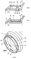
- Fig. 5 now shows again in perspective view the larger end portion of the bellows-type cover with the temporarily held clamping member 40 before shrinkage.
- two outer retaining means or projections 20 are visible as well as two of the inner retaining means or steps 22.
- two recesses 25 are visible, which form the punched out retaining projections 20, which are on the non-visible surface of the large end portion 11 of the bellows-type cover 10.
- the detent members 28 are not visible in the arrangement according to Fig. 5, as they are covered by the temporarily arranged clamping member 40.
- a corresponding recess 29 is visible, which has been formed by punching out the detent-like projections 28, to hold the clamping member 40 in the pre-assembled condition.
- Fig. 6 the end portion 11 of Fig. 5 is seen from the front side to show the four outer retaining projections 20, which at least partially cover the clamping ring 40 in the visible direction.
- the example shown in Figs. 5 and 6 shows the arrangement of four outer retaining projections 20 as well as four inner retaining steps 22 as an example for the better understanding of this invention.
- outer and inner retaining means which are formed by a full ring projection.
- the retaining means are blown or bent out of the end portion of the bellows-type member, it is finally a question of manufacturing and of requirements, how many retaining projections are arranged.
- detent-like member 28 which also only two, three or more projection members can be arranged as well as a fully outward extending ring, which again is protuberated, blown or bent out of the basis of the end portion, extending between the two retaining means.
- a different design of an end portion of a bellows-type member is shown, as e.g. the small end of the bellows-type member, as shown e.g. in Fig. 1.
- the outer and inner retaining projections 20 and 22 are visible, which again are preferably blown or bent out of the smaller end portion.
- two ring-like detent members 28 are arranged in the form of outward extending projections.
- Within the open end of the small end 13 of the bellows-type cover 10 at least partially the corresponding a ring forming recess 29 is shown to demonstrate that again the detent-like projections 28 are blow-moulded or blow-extruded out of the end portion 13.
- Fig. 8 finally shows the end portion of Fig. 7 with the clamping ring 40 arranged before shrinkage.
- the two-tier arrangement may be used with any type of bellows made from any appropriate known elastic material whereby the detent members are designed to provide the required elasticity considering the material used for the bellows-type cover and the need for yieldingness to permit a release of the temporary radially outer position of the integrated clamping member.
- the detent members may be arranged between two retaining projections, but of course may be arranged at any place around the surface of the end portion of the bellows which is determined for the engagement of the clamp-like member.
- the detent-like member and the outer retaining means do not have to be within one line.
- the inner retaining means, the detent-like member as well as the outer retaining means may be arranged in staggered relationship, so that one first retaining means or detent member on one side is followed in a staggered manner in the circumferential direction by the next second retaining means or detent member on the other side, and so on.
- the flank surface 12 needs not to be rectilinear, but may also have a curved configuration of any appropriate shape.
Abstract
Description
- The invention relates to a bellows-type cover made from elastic material, such as rubber or plastic material, used, for instance, for the protection of universal joints and drive shafts in which a clamping member or members such as hose clamps or shrinkable compression rings are integrated with the bellows-type cover.
- Flexible or elastic bellows-type covers usually of accordion-like construction, such as axle boots for universal joints or for drive shafts, must be carefully sealed to protect the lubricant. Such bellows-type covers have been used extensively in the automotive industry, for example to protect joints at a drive shaft. They are normally fastened to the axle stub shafts by means of hose clamps or shrinkable compression rings. A need exists at present on the part of manufacturers of universal joint shafts or drive shafts for bellows-type covers in which clamping members in the form of "Oetiker" hose clamps or "Oetiker" shrinkable compression rings are already integrated into the bellows-type covers. In other words, the manufacturers desire a product in which the clamping members are already integrated at or in the bellows-type covers which favours the automatic assembly of the universal joint or drive shafts in that the bellows-type covers provided with integrated clamping members are available as pre-assembled parts so as to avoid the need for mounting the clamping members on the bellows-type covers only at the final assembly as is the case today.
- Two possibilities exist, in principle, for a clamping member to be integrated into the bellows-type cover which consist of (1) the clamping member vulcanised into the bellows-type cover or (2) a self-holding arrangement for a clamping member adapted to be mounted on the bellows-type cover. Of these two possibilities, the first solution involving the clamping member vulcanised into the bellows-type cover can be disregarded because such an arrangement is practically not feasible with the usual hose clamps presently used as clamping members as also with compression rings used as clamping members. For example, a stepless hose clamp of the type disclosed in the U.S. Patent 4,299,012, which has been used extensively with axle boots in the automotive industry, if vulcanised into the bellows-type cover, would present great difficulty of being tightened by deforming the "Oetiker" ear. The vulcanised-in solution is also unacceptable because of substantial increase in costs. A shrinkable compression ring, vulcanised into the bellows-type cover can no longer be shrunk by means of the presently available tools because these tools are designed to engage during the shrinking operation with the external surface of the compression ring having a predetermined diameter in a form-locking manner in order to reduce the compression ring in its diametric dimension by the application of radial forces. The layer of rubber or plastic material applied over the vulcanised-in shrinkable compression ring formed by the vulcanising operation prevents a form-locking connection between the compression ring and the compression tool. Equally inappropriate are arguments that vulcanising-in of the clamping members into the bellows-type covers provides a corrosion protection of the integrated hose clamps or compression rings because these problems can be readily avoided in the present invention by the use of appropriate materials for the clamping devices, such as stainless steel or aluminum. Furthermore, a vulcanising-in of the clamping members precludes any visual control provided at the clamping member in the installed condition insofar as correct positioning and seating of the clamping member and proper tightening of the clamping member are concerned. Visual inspection of indications relating to manufacturer of the clamping members and/or installation dates would also become impossible. Up to the present, hose clamps used with drive or universal joint shafts have served extensively as information carriers in that dates such as assembly dates or other relevant dates of interest to the manufacturer were integrated into the clamping devices, for example, by stamping. Such visual inspections and controls are possible only as long as the clamping members are freely exposed which is not the case with a vulcanised-in solution.
- According to one embodiment of this invention, the pre-assembled unit consists of a bellows-type cover of rubber or plastic material and of an "Oetiker" shrinkable compression ring or hose clamp of metal, both readily mass-producible items, in which the clamping member, as customary to date, is installed between first and second retaining means protruding from the external diameter for receiving the clamping member at both ends of the bellows-type cover, i.e., in the small as also in the large outer diameter area of the bellows-type cover. To date, groove-shaped recesses formed by fully around extending retaining means serve exclusively for the correct guidance of the clamping member in the fully installed condition but are unable to provide any self-retaining function for a pre-assembled clamping member such as a compression ring integrated into the bellows-type cover.
- According to a preferred embodiment of this invention, the bellows-type cover at the section of the retaining means for receiving the clamping member is of two-tier construction in that it is now provided with at least one, preferably with several, detent elements along the circumference thereof between the retaining means which position and hold the compression ring in a self-retaining manner, once placed between the retaining means prior to tightening or shrinking of the clamping member. The clamping member, such as a compression ring, can now be removed again from the bellows-type cover only with the use of large forces. As a result thereof, the clamping member such as a compression ring which is now automatically retained after being mounted on the bellows-type cover between the retaining means, now forms an integrated unit with the bellows-type cover for further processing the integrated unit of bellows-type cover and clamping member. The use of detent elements offers the advantage of providing a two-tier structure for accommodating the clamping member in which the radially outer position securely but only temporarily holds the clamping member as a part integrated into the bellows-type cover yet permits complete, reliable tightening of the clamping member by releasing the temporary radially outer position in the presence of predetermined tightening forces. The term "clamping member" is used in this application to describe both conventional clamps such as "Oetiker" stepless clamps as presently used with bellows-type covers as also shrinkable compression rings such as "Oetiker" puzzle lock compression rings as disclosed in U.S. Patents 5,001,816 and 5,185,908, or any other kind of so-called press rings, clamping rings or shrinkable compression rings.
- These and other objects, features and advantages of this invention will become more apparent from the following description when taken in connection with the accompanying drawings which show, for purposes of illustration only, embodiments in accordance with the present invention, and wherein:
- Fig. 1
- is a schematic side-view of a bellows-type cover in accordance with the present invention;
- Fig. 2
- is a partial axial cross-sectional view through an end part of a bellows-type cover in accordance with Fig. 1 (along line I-I);
- Fig. 3
- is an enlarged partial axial cross-sectional view through one end of the bellows-type cover of Fig. 2, showing a clamping member in the form of a compression ring in the integrated, pre-assembled condition;
- Fig. 4
- is an enlarged partial axial cross-sectional view, similar to Fig. 3, showing the clamping member in the fully installed condition after the shrinking operation;
- Fig. 5
- is a perspective view of a bellows-type cover, similar to the one shown in Fig. 1, including a temporarily held clamping member before tightening;
- Fig. 6
- the bellows-type cover with clamping member according to Fig. 5 in a view from the front side of the bellows-type cover;
- Fig. 7
- a perspective view of the end part of a bellows-type cover, similar to the one shown in Fig. 1, with a different design of the one end, and
- Fig. 8
- the end of the bellows-type cover according to Fig. 7, holding a temporary clamping member before tightening or shrinking of the clamping member.
- Referring now to the drawing wherein like reference numerals are used throughout the various views to designate like parts,
reference numeral 10 generally designates a bellows-type cover of elastic material such as rubber or plastic material which may be of any known construction. The two-tier arrangement provided, for example, at the large end of the bellows-type cover 10 is generally designated byreference numeral 11 which is provided with e.g. four circumferentially arranged first outer and second inner retaining projections, designated byreference numerals projections side walls reference numeral 40. The radial depth of the projections is thereby slightly larger than the thickness of theclamping member 40. The radiallyouter retaining projections 20 of the structure are preferably formed by blown or bent out portions of theend portion 11 formingcorresponding recesses 25. The radially inner retaining means 22 of the structure are formed by steps or projections within the outer side wall of thefirst bellows 31 of the bellows-type cover 10, which might be obtained by blow moulding or blow extrusion, using a correspondingly shaped tool. Within theupper surface 27 of therecess 26 extending between the twoprojections projections 28 which are circumferentially arranged are protuberated or bent out from thesurface 27, formingcorresponding recesses 29 on the backside of thebasis 27. The detent-like members orprojections 28 are integral with the basis of thelarger end 11 of the bellows-type cover 10 and are therefore made of the same elastic material which permits yielding thereof. In addition, preferably on both sides of the detent-like members orprojections 25 small ornarrow grooves 33 are arranged, which are preferably extending circumferentially around thewhole surface 27. In addition, on the backside of thebasis 27 in the section of the detent-like member 1 or 2projections 35 are arranged, which are extending circumferentially along the backside of thebasis 27 and which are provided to engage in corresponding recesses arranged on the metal surface of the shaft, on which the bellows-type cover member is to be secured. - As shown in Fig. 1, the detent-like members, such as three, four or more, are distributed uniformly over the circumference of the
basis 27 and retain theclamping member 40 such as an "Oetiker" puzzle-lock compression ring in the pre-assembled condition in which theclamping member 40 is securely held integrated with the bellows-type cover 10 because of the self-retaining function of the upper part of theside walls projections like members 28. Upon application of tightening forces, the detent-like members 28 are able to yield to permit theclamping member 40 to enter the radially inward part of the groove-shapedrecess 26 extending between theprojections basis 27 of the groove-shaped recess 26 as a result of the tightening, respectively, shrinking of the diametric dimension thereof. - As mentioned above, the use of groove-shaped recesses in the external surfaces of the ends of bellows-type covers are known. However, up to now, they merely served the purpose of guiding the clamping member in the fully installed condition. The problem of providing a two-tier arrangement in which a self-holding feature is also attained in the radially outer position would not be attainable without the use of the detent-
like members 28, because even a deeper recess between theretaining projections retaining projections outer projection 22. Detent-like members in the form of elastic outward extendingprojections 28 which provide a temporary radially outer position of the two-tier arrangement with a completely safe retaining function to achieve the required integration are therefore necessary to assure an assembly of a bellows-type cover with integrated clamping member. Theexternal surface 12 of the outer end of theouter retaining projections 20 is thereby inclined to form a rectilinearly obliquely upwardly extending flank to assist in centering and mounting the clamping ring in the recess between theretaining projections - The bellows-
type cover 10 is made of rubber, a thermoplastic or another elastomeric polymer material, such as polyester or polyamid elastomeric material, as e.g. of Hytrel, and is to be fastened over a metallic axle stub by means of a shrinkable compression ring such as an "Oetiker" puzzle-type compression ring as disclosed in the aforementioned U.S. patents. - Fig. 5 now shows again in perspective view the larger end portion of the bellows-type cover with the temporarily held
clamping member 40 before shrinkage. In the perspective view of Fig. 5, two outer retaining means orprojections 20 are visible as well as two of the inner retaining means or steps 22. Within the open end of the end portion on the other hand tworecesses 25 are visible, which form the punched out retainingprojections 20, which are on the non-visible surface of thelarge end portion 11 of the bellows-type cover 10. In addition, thedetent members 28 are not visible in the arrangement according to Fig. 5, as they are covered by the temporarily arranged clampingmember 40. On the other hand, again within the open end of thelarge end portion 11, a correspondingrecess 29 is visible, which has been formed by punching out the detent-like projections 28, to hold the clampingmember 40 in the pre-assembled condition. - In Fig. 6 the
end portion 11 of Fig. 5 is seen from the front side to show the fourouter retaining projections 20, which at least partially cover theclamping ring 40 in the visible direction. The example shown in Figs. 5 and 6 shows the arrangement of fourouter retaining projections 20 as well as four inner retaining steps 22 as an example for the better understanding of this invention. Of course it is possible to arrange also three or five, six or more retaining means. It is even possible to arrange outer and inner retaining means, which are formed by a full ring projection. As according to the invention, preferably the retaining means are blown or bent out of the end portion of the bellows-type member, it is finally a question of manufacturing and of requirements, how many retaining projections are arranged. The same has to me mentioned in relation to the detent-like member 28, of which also only two, three or more projection members can be arranged as well as a fully outward extending ring, which again is protuberated, blown or bent out of the basis of the end portion, extending between the two retaining means. - In Fig. 7 a different design of an end portion of a bellows-type member is shown, as e.g. the small end of the bellows-type member, as shown e.g. in Fig. 1. Again, the outer and
inner retaining projections projections like detent members 28 are arranged in the form of outward extending projections. Within the open end of thesmall end 13 of the bellows-type cover 10 at least partially the corresponding aring forming recess 29 is shown to demonstrate that again the detent-like projections 28 are blow-moulded or blow-extruded out of theend portion 13. - Fig. 8 finally shows the end portion of Fig. 7 with the clamping
ring 40 arranged before shrinkage. - While only a few embodiments have been shown and described in accordance with the present invention, it is understood that the same is not limited thereto but is susceptible of numerous changes and modifications as known to those skilled in the art. The two-tier arrangement may be used with any type of bellows made from any appropriate known elastic material whereby the detent members are designed to provide the required elasticity considering the material used for the bellows-type cover and the need for yieldingness to permit a release of the temporary radially outer position of the integrated clamping member. Furthermore, the detent members may be arranged between two retaining projections, but of course may be arranged at any place around the surface of the end portion of the bellows which is determined for the engagement of the clamp-like member. In other words, in axial direction of the bellows the inner retaining means, the detent-like member and the outer retaining means do not have to be within one line. The inner retaining means, the detent-like member as well as the outer retaining means may be arranged in staggered relationship, so that one first retaining means or detent member on one side is followed in a staggered manner in the circumferential direction by the next second retaining means or detent member on the other side, and so on. Additionally, the
flank surface 12 needs not to be rectilinear, but may also have a curved configuration of any appropriate shape. - As a consequence therefore the present invention is not at all limited to the details shown and described herein, but is intended to cover all such changes and modifications as are encompassed by the scope of the appended claims.
Claims (19)
- A bellows-type cover member for an integratable clamping member to form a pre-assembled unit, comprising first and second retaining means (20, 22) in the bellows-type cover member (10) for receiving a clamping member (40), said first and second retaining means being at a distance which corresponds approximately with the width of the clamping member, so that the clamping member may be arranged in engagement between the said first and second retaining means in the fully installed position thereof, and further means (28) between the first and second retaining means to provide a self-retaining support for the clamping member in a pre-assembled position at a distance of the bottom surface of the bellows-type cover member between the first and second retaining means.
- A bellows-type cover member according to claim 1, wherein said further means is operable to release the temporary retaining support bottom in the presence of radially inwardly directed forces to enable the clamping member to move from said pre-assembled position to the fully installed position.
- A bellows-type cover member according to claim 1 or 2, wherein said further means is yieldable.
- A bellows-type cover member according to any one of claims 1 - 3, wherein said further means includes at least one detent member extending at least partially around the bottom section of the bellows-type cover member extending between the first and second retaining means and which is protuberated, blown or bent out of the bottom section extending radially outwardly to form the temporary retaining support bottom.
- A bellows-type cover member according to claim 4, wherein at least on one side of the one detent member within the bottom section an at least partially along the circumference of the bottom section extending groove or recess (33) is provided.
- A bellows-type cover member according to any one of claims 1 to 5, wherein on the backside surface of the bottom surface of the bellows-type cover member extending between the first and second retaining means at least one in circumferential direction extending projection is arranged, provided for the engagement into a corresponding groove or recess on a surface, on which the bellows-type cover member is to be secured.
- A bellows-type cover member according to one of the claims 4 to 6, wherein said further means is extending along the full circumference of the bottom section, extending between said first and second retaining means.
- A bellows-type cover member according to one of the claims 1 to 7, wherein said further means include at least two or more detent members extending between said first and second retaining means and which are provided at a distance along the circumference of said bottom section.
- Bellows-type cover member according to claim 8, wherein at least two detent members are provided along the circumference of said bottom section and at least two detent members in an offset direction along the longitudinal axis of the bellows-type cover member.
- Bellows-type cover member according to one of the claims 1 to 9, wherein at least said first retaining means are obtained by blow-moulding or blow-extrusion out of the bellows-type cover member forming corresponding recesses on the backside surface opposite to the surface forming the retaining means.
- Bellows-type cover member according to claim 10, wherein two or more first and second retaining means are provided along the circumference of said bellows-type cover member.
- Bellows-type cover member according to one of claims 1 to 11, wherein at least three, preferably four or more, first and second retaining means are arranged for receiving a clamping member between the first and second retaining means.
- Bellows-type cover member according to any one of claims 1 to 12, wherein said bellows-type cover member includes a clamping member arranged between the first and second retaining means as an integrated part thereof.
- Bellows-type cover member according to claim 13, wherein said clamping member is supported in a pre-assembled position by the further means which provide a self-retaining support position to carry the clamping member.
- An assembly of a bellows-type cover means with a pre-assembled integrated clamping member adapted to be received between first and second retaining means provided in the bellows-type cover member, characterised in that the section of the bellows-type cover means extending between the first and second retaining means includes further means providing a two-tier positioning of the clamping member in which in a first position the clamping member is integrated with the bellows-type cover means corresponding to the not-yet-tightened condition of the clamping member and in which, in a second position, the clamping member is in the installed tightened position.
- An assembly according to claim 15, wherein said further means is operable to provide a self-retaining action on the clamping member in said first position at a substantially constant radial distance with respect to the bellows-type cover means.
- An assembly according to claim 15 or 16, wherein said further means is formed by axially extending projection means for non-removably retaining the clamping member in said recess means, and wherein said projection means are yieldable in the presence of tightening forces seeking to displace the clamping member from the first to the second position.
- An assembly according to claim 17, wherein said projection means are punched-out sections within the bellows-type cover means section extending between the first and second retaining means.
- An assembly according to any one of the claims 15 to 18, wherein at least the first retaining means are formed by blow-moulded or blow-extruded sections within the bellows-type cover means.
Priority Applications (15)
| Application Number | Priority Date | Filing Date | Title |
|---|---|---|---|
| PT98118715T PT990810E (en) | 1998-10-02 | 1998-10-02 | COVERING COMPONENTS TYPE FOLE |
| DE69814074T DE69814074T2 (en) | 1998-10-02 | 1998-10-02 | Bellows-shaped cover |
| ES98118715T ES2199394T3 (en) | 1998-10-02 | 1998-10-02 | FUELLE TYPE COVER ELEMENT. |
| EP98118715A EP0990810B1 (en) | 1998-10-02 | 1998-10-02 | Bellows-type cover member |
| AT98118715T ATE239182T1 (en) | 1998-10-02 | 1998-10-02 | BELLOWS-SHAPED COVER |
| JP2000574851A JP2002526728A (en) | 1998-10-02 | 1999-09-13 | Bellows type cover member |
| MXPA01002985A MXPA01002985A (en) | 1998-10-02 | 1999-09-13 | Bellows-type cover member. |
| US09/806,534 US6464233B1 (en) | 1998-10-02 | 1999-09-13 | Bellows-type cover member |
| CA002345579A CA2345579A1 (en) | 1998-10-02 | 1999-09-13 | Bellows-type cover member |
| KR1020017003932A KR20010079938A (en) | 1998-10-02 | 1999-09-13 | Bellows-type cover member |
| PCT/CH1999/000430 WO2000020773A1 (en) | 1998-10-02 | 1999-09-13 | Bellows-type cover member |
| CN99811587A CN1320198A (en) | 1998-10-02 | 1999-09-13 | Bellows-type cover member |
| AU55014/99A AU751638B2 (en) | 1998-10-02 | 1999-09-13 | Bellows-type cover member |
| BR9914141-8A BR9914141A (en) | 1998-10-02 | 1999-09-13 | Bellows type cover element, e, set of bellows type cover means with a pre-assembled integrated gripping element |
| ZA200102487A ZA200102487B (en) | 1998-10-02 | 2001-03-27 | Bellows-type cover member. |
Applications Claiming Priority (1)
| Application Number | Priority Date | Filing Date | Title |
|---|---|---|---|
| EP98118715A EP0990810B1 (en) | 1998-10-02 | 1998-10-02 | Bellows-type cover member |
Publications (2)
| Publication Number | Publication Date |
|---|---|
| EP0990810A1 true EP0990810A1 (en) | 2000-04-05 |
| EP0990810B1 EP0990810B1 (en) | 2003-05-02 |
Family
ID=8232744
Family Applications (1)
| Application Number | Title | Priority Date | Filing Date |
|---|---|---|---|
| EP98118715A Expired - Lifetime EP0990810B1 (en) | 1998-10-02 | 1998-10-02 | Bellows-type cover member |
Country Status (15)
| Country | Link |
|---|---|
| US (1) | US6464233B1 (en) |
| EP (1) | EP0990810B1 (en) |
| JP (1) | JP2002526728A (en) |
| KR (1) | KR20010079938A (en) |
| CN (1) | CN1320198A (en) |
| AT (1) | ATE239182T1 (en) |
| AU (1) | AU751638B2 (en) |
| BR (1) | BR9914141A (en) |
| CA (1) | CA2345579A1 (en) |
| DE (1) | DE69814074T2 (en) |
| ES (1) | ES2199394T3 (en) |
| MX (1) | MXPA01002985A (en) |
| PT (1) | PT990810E (en) |
| WO (1) | WO2000020773A1 (en) |
| ZA (1) | ZA200102487B (en) |
Cited By (4)
| Publication number | Priority date | Publication date | Assignee | Title |
|---|---|---|---|---|
| DE10324391A1 (en) * | 2003-05-30 | 2004-12-23 | Contitech Vibration Control Gmbh | Sealing and fastening of a cuff |
| WO2006066603A1 (en) * | 2004-12-21 | 2006-06-29 | Gkn Driveline International Gmbh | System for fixing a bellows-type device to a part comprising at least one lobed area |
| WO2008040368A1 (en) * | 2006-09-29 | 2008-04-10 | Gkn Driveline International Gmbh | Bellows comprising a receiver for a retaining ring and method for producing the same |
| WO2008040369A1 (en) * | 2006-09-29 | 2008-04-10 | Gkn Driveline International Gmbh | Bellows for a joint arrangement, comprising a receiver for a retaining ring |
Families Citing this family (16)
| Publication number | Priority date | Publication date | Assignee | Title |
|---|---|---|---|---|
| ATE324246T1 (en) * | 2002-04-08 | 2006-05-15 | Toyo Tire & Rubber Co | METHOD FOR MAKING A RESIN SEALING SEAL |
| US7017436B2 (en) * | 2002-10-10 | 2006-03-28 | General Motors Corporation | Boot assembly for a vehicle |
| JP4322707B2 (en) * | 2004-02-27 | 2009-09-02 | 豊田合成株式会社 | Constant velocity joint boots |
| US7147229B2 (en) * | 2004-03-15 | 2006-12-12 | Federal Mogul World Wide Inc. | Shaft seal assembly with retaining ring and washer |
| US7297065B2 (en) * | 2004-12-08 | 2007-11-20 | Gkn Driveline North America, Inc. | Automotive driveline components manufactured of silicone materials |
| JP4434004B2 (en) * | 2004-12-10 | 2010-03-17 | 豊田合成株式会社 | Constant velocity joint boots |
| JP4440134B2 (en) * | 2005-02-16 | 2010-03-24 | 津田駒工業株式会社 | Loom opening device cover |
| JP4419877B2 (en) * | 2005-03-14 | 2010-02-24 | 豊田合成株式会社 | Constant velocity joint boots |
| CN102209862B (en) * | 2008-09-12 | 2014-12-03 | Gkn动力传动系统国际有限责任公司 | Boot comprising an attachment region with at least two circumferential outside ribs |
| WO2012025129A1 (en) * | 2010-08-24 | 2012-03-01 | Gkn Driveline International Gmbh | Boot for joints, especially for constant velocity joints, with a transition area |
| ES2533037T3 (en) * | 2012-11-13 | 2015-04-07 | Carl Freudenberg Kg | Sleeve |
| JP6448201B2 (en) * | 2014-03-18 | 2019-01-09 | 株式会社ショーワ | Steering device |
| DE102016201046A1 (en) * | 2016-01-26 | 2017-07-27 | Zf Friedrichshafen Ag | Ball joint for a vehicle, in particular for an off-road vehicle |
| JP6884010B2 (en) * | 2017-03-16 | 2021-06-09 | Ntn株式会社 | Boots for constant velocity universal joints |
| FR3069814B1 (en) * | 2017-08-01 | 2019-08-09 | Psa Automobiles Sa | DEVICE FOR PROTECTING AN OCCUPANT OF A VEHICLE SEAT WITHIN A SYSTEM FOR INCLINING THE BACKREST OF SUCH A SEAT AND METHOD OF FASTENING SUCH A DEVICE. |
| CN107477100B (en) * | 2017-09-30 | 2019-11-22 | 北京新能源汽车股份有限公司 | Joint arrangement and vehicle with it |
Citations (6)
| Publication number | Priority date | Publication date | Assignee | Title |
|---|---|---|---|---|
| EP0425864A1 (en) * | 1989-10-31 | 1991-05-08 | GKN Automotive AG | Bellows |
| JPH06341551A (en) * | 1993-05-31 | 1994-12-13 | Kyoraku Co Ltd | Boot |
| EP0669476A1 (en) * | 1994-02-24 | 1995-08-30 | Draftex Industries Limited | Protective bellows |
| GB2287073A (en) * | 1994-02-24 | 1995-09-06 | Draftex Ind Ltd | Mounting clamp on protective bellows |
| DE19507597A1 (en) * | 1995-03-04 | 1996-09-12 | Contitech Formteile Gmbh | Folding bellows formed from thermoplastic elastomer |
| EP0809034A1 (en) * | 1996-05-21 | 1997-11-26 | Hans Oetiker AG Maschinen- und Apparatefabrik | Bellows-type cover with integrated clamping member |
Family Cites Families (3)
| Publication number | Priority date | Publication date | Assignee | Title |
|---|---|---|---|---|
| GB2282208B (en) * | 1993-09-28 | 1997-05-14 | Ntn Toyo Bearing Co Ltd | Resin boot |
| FR2771145B1 (en) * | 1997-11-19 | 2000-02-25 | Car X | FLEXIBLE SHEATH WITH BELLOWS FOR ARTICULATED JOINT AND TOOLS FOR PLACING THIS SHEATH |
| JP4203688B2 (en) * | 1998-04-23 | 2009-01-07 | Nok株式会社 | Universal joint boots |
-
1998
- 1998-10-02 AT AT98118715T patent/ATE239182T1/en not_active IP Right Cessation
- 1998-10-02 ES ES98118715T patent/ES2199394T3/en not_active Expired - Lifetime
- 1998-10-02 PT PT98118715T patent/PT990810E/en unknown
- 1998-10-02 EP EP98118715A patent/EP0990810B1/en not_active Expired - Lifetime
- 1998-10-02 DE DE69814074T patent/DE69814074T2/en not_active Expired - Fee Related
-
1999
- 1999-09-13 JP JP2000574851A patent/JP2002526728A/en active Pending
- 1999-09-13 MX MXPA01002985A patent/MXPA01002985A/en not_active Application Discontinuation
- 1999-09-13 WO PCT/CH1999/000430 patent/WO2000020773A1/en not_active Application Discontinuation
- 1999-09-13 CA CA002345579A patent/CA2345579A1/en not_active Abandoned
- 1999-09-13 KR KR1020017003932A patent/KR20010079938A/en not_active Application Discontinuation
- 1999-09-13 BR BR9914141-8A patent/BR9914141A/en active Search and Examination
- 1999-09-13 AU AU55014/99A patent/AU751638B2/en not_active Ceased
- 1999-09-13 CN CN99811587A patent/CN1320198A/en active Pending
- 1999-09-13 US US09/806,534 patent/US6464233B1/en not_active Expired - Fee Related
-
2001
- 2001-03-27 ZA ZA200102487A patent/ZA200102487B/en unknown
Patent Citations (6)
| Publication number | Priority date | Publication date | Assignee | Title |
|---|---|---|---|---|
| EP0425864A1 (en) * | 1989-10-31 | 1991-05-08 | GKN Automotive AG | Bellows |
| JPH06341551A (en) * | 1993-05-31 | 1994-12-13 | Kyoraku Co Ltd | Boot |
| EP0669476A1 (en) * | 1994-02-24 | 1995-08-30 | Draftex Industries Limited | Protective bellows |
| GB2287073A (en) * | 1994-02-24 | 1995-09-06 | Draftex Ind Ltd | Mounting clamp on protective bellows |
| DE19507597A1 (en) * | 1995-03-04 | 1996-09-12 | Contitech Formteile Gmbh | Folding bellows formed from thermoplastic elastomer |
| EP0809034A1 (en) * | 1996-05-21 | 1997-11-26 | Hans Oetiker AG Maschinen- und Apparatefabrik | Bellows-type cover with integrated clamping member |
Non-Patent Citations (1)
| Title |
|---|
| PATENT ABSTRACTS OF JAPAN vol. 095, no. 003 28 April 1995 (1995-04-28) * |
Cited By (8)
| Publication number | Priority date | Publication date | Assignee | Title |
|---|---|---|---|---|
| DE10324391A1 (en) * | 2003-05-30 | 2004-12-23 | Contitech Vibration Control Gmbh | Sealing and fastening of a cuff |
| DE10324391B4 (en) * | 2003-05-30 | 2013-02-21 | Contitech Vibration Control Gmbh | Seal and attach a cuff |
| WO2006066603A1 (en) * | 2004-12-21 | 2006-06-29 | Gkn Driveline International Gmbh | System for fixing a bellows-type device to a part comprising at least one lobed area |
| WO2008040368A1 (en) * | 2006-09-29 | 2008-04-10 | Gkn Driveline International Gmbh | Bellows comprising a receiver for a retaining ring and method for producing the same |
| WO2008040369A1 (en) * | 2006-09-29 | 2008-04-10 | Gkn Driveline International Gmbh | Bellows for a joint arrangement, comprising a receiver for a retaining ring |
| US8157661B2 (en) | 2006-09-29 | 2012-04-17 | Gkn Driveline International Gmbh | Bellows comprising a receiver for a retaining ring and method for producing the same |
| DE112006003945B4 (en) * | 2006-09-29 | 2014-04-03 | Gkn Driveline International Gmbh | Bellows for a joint arrangement with a receptacle for a retaining ring |
| DE112006004038B4 (en) * | 2006-09-29 | 2017-01-19 | Gkn Driveline International Gmbh | Bellows with a receptacle for a retaining ring and method for its production |
Also Published As
| Publication number | Publication date |
|---|---|
| US6464233B1 (en) | 2002-10-15 |
| CN1320198A (en) | 2001-10-31 |
| DE69814074D1 (en) | 2003-06-05 |
| AU5501499A (en) | 2000-04-26 |
| MXPA01002985A (en) | 2002-04-24 |
| AU751638B2 (en) | 2002-08-22 |
| EP0990810B1 (en) | 2003-05-02 |
| ATE239182T1 (en) | 2003-05-15 |
| JP2002526728A (en) | 2002-08-20 |
| WO2000020773A1 (en) | 2000-04-13 |
| CA2345579A1 (en) | 2000-04-13 |
| DE69814074T2 (en) | 2004-02-26 |
| BR9914141A (en) | 2001-06-19 |
| PT990810E (en) | 2003-09-30 |
| KR20010079938A (en) | 2001-08-22 |
| ES2199394T3 (en) | 2004-02-16 |
| ZA200102487B (en) | 2001-11-08 |
Similar Documents
| Publication | Publication Date | Title |
|---|---|---|
| EP0990810B1 (en) | Bellows-type cover member | |
| CA2204454C (en) | Bellows-type cover with integrated clamping member | |
| EP0942189B1 (en) | Boot with insertable bushing | |
| EP0915264B2 (en) | Protective bellows | |
| US7513831B2 (en) | Power transmission device with slip spline shaft assembly having boot integrated deflector | |
| EP1293692B1 (en) | Joint boot made of resin | |
| EP0672848A1 (en) | Protective bellows | |
| JPH07269708A (en) | Protective bellows | |
| EP0887582B1 (en) | Mounting arrangement of partially tightened clamp structure on hose-like member | |
| EP2630382B1 (en) | Folding bellows arrangement for a tripod joint unit | |
| MXPA97003706A (en) | Cover type of bellows with integr fixed member | |
| JP2021042833A (en) | Boot for constant velocity universal joint | |
| JPH10311053A (en) | Method for sealing a space between circular wall forming an opening part and pipe end part inserted into opening part | |
| JPH0728267U (en) | Oil seal | |
| JP4012186B2 (en) | Joint boots | |
| JP2598534Y2 (en) | Boots for constant velocity joints | |
| JPH0752475Y2 (en) | Mouth cap | |
| JP2006118612A (en) | Joint boot | |
| JP3550434B2 (en) | Resin CVJ boots | |
| JPH0755000A (en) | Boot fixing structure | |
| JP2005003160A (en) | Resin joint boot |
Legal Events
| Date | Code | Title | Description |
|---|---|---|---|
| PUAI | Public reference made under article 153(3) epc to a published international application that has entered the european phase |
Free format text: ORIGINAL CODE: 0009012 |
|
| AK | Designated contracting states |
Kind code of ref document: A1 Designated state(s): AT BE CH DE ES FR GB IT LI NL PT SE |
|
| AX | Request for extension of the european patent |
Free format text: AL;LT;LV;MK;RO;SI |
|
| 17P | Request for examination filed |
Effective date: 20000330 |
|
| AKX | Designation fees paid |
Free format text: AT BE CH DE ES FR GB IT LI NL PT SE |
|
| 17Q | First examination report despatched |
Effective date: 20020416 |
|
| GRAH | Despatch of communication of intention to grant a patent |
Free format text: ORIGINAL CODE: EPIDOS IGRA |
|
| GRAH | Despatch of communication of intention to grant a patent |
Free format text: ORIGINAL CODE: EPIDOS IGRA |
|
| GRAA | (expected) grant |
Free format text: ORIGINAL CODE: 0009210 |
|
| AK | Designated contracting states |
Designated state(s): AT BE CH DE ES FR GB IT LI NL PT SE |
|
| REG | Reference to a national code |
Ref country code: GB Ref legal event code: FG4D |
|
| REG | Reference to a national code |
Ref country code: CH Ref legal event code: EP |
|
| REF | Corresponds to: |
Ref document number: 69814074 Country of ref document: DE Date of ref document: 20030605 Kind code of ref document: P |
|
| REG | Reference to a national code |
Ref country code: CH Ref legal event code: NV Representative=s name: SULZER MANAGEMENT AG |
|
| REG | Reference to a national code |
Ref country code: SE Ref legal event code: TRGR |
|
| REG | Reference to a national code |
Ref country code: PT Ref legal event code: SC4A Free format text: AVAILABILITY OF NATIONAL TRANSLATION Effective date: 20030731 |
|
| PGFP | Annual fee paid to national office [announced via postgrant information from national office to epo] |
Ref country code: GB Payment date: 20031001 Year of fee payment: 6 |
|
| PGFP | Annual fee paid to national office [announced via postgrant information from national office to epo] |
Ref country code: FR Payment date: 20031003 Year of fee payment: 6 |
|
| PGFP | Annual fee paid to national office [announced via postgrant information from national office to epo] |
Ref country code: SE Payment date: 20031007 Year of fee payment: 6 |
|
| PGFP | Annual fee paid to national office [announced via postgrant information from national office to epo] |
Ref country code: NL Payment date: 20031008 Year of fee payment: 6 |
|
| PGFP | Annual fee paid to national office [announced via postgrant information from national office to epo] |
Ref country code: DE Payment date: 20031009 Year of fee payment: 6 |
|
| PGFP | Annual fee paid to national office [announced via postgrant information from national office to epo] |
Ref country code: AT Payment date: 20031013 Year of fee payment: 6 |
|
| PGFP | Annual fee paid to national office [announced via postgrant information from national office to epo] |
Ref country code: ES Payment date: 20031128 Year of fee payment: 6 |
|
| PGFP | Annual fee paid to national office [announced via postgrant information from national office to epo] |
Ref country code: BE Payment date: 20031211 Year of fee payment: 6 |
|
| PGFP | Annual fee paid to national office [announced via postgrant information from national office to epo] |
Ref country code: CH Payment date: 20031223 Year of fee payment: 6 |
|
| ET | Fr: translation filed | ||
| REG | Reference to a national code |
Ref country code: ES Ref legal event code: FG2A Ref document number: 2199394 Country of ref document: ES Kind code of ref document: T3 |
|
| PLBE | No opposition filed within time limit |
Free format text: ORIGINAL CODE: 0009261 |
|
| STAA | Information on the status of an ep patent application or granted ep patent |
Free format text: STATUS: NO OPPOSITION FILED WITHIN TIME LIMIT |
|
| 26N | No opposition filed |
Effective date: 20040203 |
|
| PGFP | Annual fee paid to national office [announced via postgrant information from national office to epo] |
Ref country code: PT Payment date: 20040928 Year of fee payment: 7 |
|
| PG25 | Lapsed in a contracting state [announced via postgrant information from national office to epo] |
Ref country code: GB Free format text: LAPSE BECAUSE OF NON-PAYMENT OF DUE FEES Effective date: 20041002 Ref country code: AT Free format text: LAPSE BECAUSE OF NON-PAYMENT OF DUE FEES Effective date: 20041002 |
|
| PG25 | Lapsed in a contracting state [announced via postgrant information from national office to epo] |
Ref country code: SE Free format text: LAPSE BECAUSE OF NON-PAYMENT OF DUE FEES Effective date: 20041003 |
|
| PG25 | Lapsed in a contracting state [announced via postgrant information from national office to epo] |
Ref country code: ES Free format text: LAPSE BECAUSE OF NON-PAYMENT OF DUE FEES Effective date: 20041004 |
|
| PG25 | Lapsed in a contracting state [announced via postgrant information from national office to epo] |
Ref country code: LI Free format text: LAPSE BECAUSE OF NON-PAYMENT OF DUE FEES Effective date: 20041031 Ref country code: CH Free format text: LAPSE BECAUSE OF NON-PAYMENT OF DUE FEES Effective date: 20041031 Ref country code: BE Free format text: LAPSE BECAUSE OF NON-PAYMENT OF DUE FEES Effective date: 20041031 |
|
| BERE | Be: lapsed |
Owner name: HANS *OETIKER A.G. MASCHINEN- UND APPARATEFABRIK Effective date: 20041031 |
|
| PG25 | Lapsed in a contracting state [announced via postgrant information from national office to epo] |
Ref country code: NL Free format text: LAPSE BECAUSE OF NON-PAYMENT OF DUE FEES Effective date: 20050501 |
|
| PG25 | Lapsed in a contracting state [announced via postgrant information from national office to epo] |
Ref country code: DE Free format text: LAPSE BECAUSE OF NON-PAYMENT OF DUE FEES Effective date: 20050503 |
|
| GBPC | Gb: european patent ceased through non-payment of renewal fee |
Effective date: 20041002 |
|
| EUG | Se: european patent has lapsed | ||
| REG | Reference to a national code |
Ref country code: CH Ref legal event code: PL |
|
| PG25 | Lapsed in a contracting state [announced via postgrant information from national office to epo] |
Ref country code: FR Free format text: LAPSE BECAUSE OF NON-PAYMENT OF DUE FEES Effective date: 20050630 |
|
| NLV4 | Nl: lapsed or anulled due to non-payment of the annual fee |
Effective date: 20050501 |
|
| REG | Reference to a national code |
Ref country code: FR Ref legal event code: ST |
|
| PG25 | Lapsed in a contracting state [announced via postgrant information from national office to epo] |
Ref country code: IT Free format text: LAPSE BECAUSE OF NON-PAYMENT OF DUE FEES Effective date: 20051002 |
|
| REG | Reference to a national code |
Ref country code: ES Ref legal event code: FD2A Effective date: 20041004 |
|
| PG25 | Lapsed in a contracting state [announced via postgrant information from national office to epo] |
Ref country code: PT Free format text: LAPSE BECAUSE OF NON-PAYMENT OF DUE FEES Effective date: 20060403 |
|
| REG | Reference to a national code |
Ref country code: PT Ref legal event code: MM4A Effective date: 20060403 |
|
| BERE | Be: lapsed |
Owner name: HANS *OETIKER A.G. MASCHINEN- UND APPARATEFABRIK Effective date: 20041031 |