EP0990807A1 - Releasable connection for fitting a body on a receiving organ - Google Patents
Releasable connection for fitting a body on a receiving organ Download PDFInfo
- Publication number
- EP0990807A1 EP0990807A1 EP99402390A EP99402390A EP0990807A1 EP 0990807 A1 EP0990807 A1 EP 0990807A1 EP 99402390 A EP99402390 A EP 99402390A EP 99402390 A EP99402390 A EP 99402390A EP 0990807 A1 EP0990807 A1 EP 0990807A1
- Authority
- EP
- European Patent Office
- Prior art keywords
- branches
- receiving member
- faces
- grooves
- wire
- Prior art date
- Legal status (The legal status is an assumption and is not a legal conclusion. Google has not performed a legal analysis and makes no representation as to the accuracy of the status listed.)
- Granted
Links
- 210000000056 organ Anatomy 0.000 title description 3
- XLYOFNOQVPJJNP-UHFFFAOYSA-N water Substances O XLYOFNOQVPJJNP-UHFFFAOYSA-N 0.000 claims description 32
- 230000005489 elastic deformation Effects 0.000 claims description 11
- 239000000463 material Substances 0.000 claims description 10
- 238000000926 separation method Methods 0.000 claims description 2
- 208000031968 Cadaver Diseases 0.000 description 13
- 230000006835 compression Effects 0.000 description 2
- 238000007906 compression Methods 0.000 description 2
- 238000012423 maintenance Methods 0.000 description 2
- 239000002184 metal Substances 0.000 description 2
- 229910052751 metal Inorganic materials 0.000 description 2
- 238000007789 sealing Methods 0.000 description 2
- YMHOBZXQZVXHBM-UHFFFAOYSA-N 2,5-dimethoxy-4-bromophenethylamine Chemical compound COC1=CC(CCN)=C(OC)C=C1Br YMHOBZXQZVXHBM-UHFFFAOYSA-N 0.000 description 1
- 241000545067 Venus Species 0.000 description 1
- 229910001297 Zn alloy Inorganic materials 0.000 description 1
- 239000002131 composite material Substances 0.000 description 1
- 239000000470 constituent Substances 0.000 description 1
- 230000000694 effects Effects 0.000 description 1
- 239000012530 fluid Substances 0.000 description 1
- 239000000446 fuel Substances 0.000 description 1
- 239000012528 membrane Substances 0.000 description 1
- 230000001105 regulatory effect Effects 0.000 description 1
Images


Classifications
-
- F—MECHANICAL ENGINEERING; LIGHTING; HEATING; WEAPONS; BLASTING
- F23—COMBUSTION APPARATUS; COMBUSTION PROCESSES
- F23N—REGULATING OR CONTROLLING COMBUSTION
- F23N1/00—Regulating fuel supply
- F23N1/08—Regulating fuel supply conjointly with another medium, e.g. boiler water
- F23N1/087—Regulating fuel supply conjointly with another medium, e.g. boiler water using mechanical means
-
- F—MECHANICAL ENGINEERING; LIGHTING; HEATING; WEAPONS; BLASTING
- F16—ENGINEERING ELEMENTS AND UNITS; GENERAL MEASURES FOR PRODUCING AND MAINTAINING EFFECTIVE FUNCTIONING OF MACHINES OR INSTALLATIONS; THERMAL INSULATION IN GENERAL
- F16B—DEVICES FOR FASTENING OR SECURING CONSTRUCTIONAL ELEMENTS OR MACHINE PARTS TOGETHER, e.g. NAILS, BOLTS, CIRCLIPS, CLAMPS, CLIPS OR WEDGES; JOINTS OR JOINTING
- F16B21/00—Means for preventing relative axial movement of a pin, spigot, shaft or the like and a member surrounding it; Stud-and-socket releasable fastenings
- F16B21/10—Means for preventing relative axial movement of a pin, spigot, shaft or the like and a member surrounding it; Stud-and-socket releasable fastenings by separate parts
- F16B21/16—Means for preventing relative axial movement of a pin, spigot, shaft or the like and a member surrounding it; Stud-and-socket releasable fastenings by separate parts with grooves or notches in the pin or shaft
-
- F—MECHANICAL ENGINEERING; LIGHTING; HEATING; WEAPONS; BLASTING
- F16—ENGINEERING ELEMENTS AND UNITS; GENERAL MEASURES FOR PRODUCING AND MAINTAINING EFFECTIVE FUNCTIONING OF MACHINES OR INSTALLATIONS; THERMAL INSULATION IN GENERAL
- F16B—DEVICES FOR FASTENING OR SECURING CONSTRUCTIONAL ELEMENTS OR MACHINE PARTS TOGETHER, e.g. NAILS, BOLTS, CIRCLIPS, CLAMPS, CLIPS OR WEDGES; JOINTS OR JOINTING
- F16B2/00—Friction-grip releasable fastenings
- F16B2/20—Clips, i.e. with gripping action effected solely by the inherent resistance to deformation of the material of the fastening
- F16B2/22—Clips, i.e. with gripping action effected solely by the inherent resistance to deformation of the material of the fastening of resilient material, e.g. rubbery material
- F16B2/24—Clips, i.e. with gripping action effected solely by the inherent resistance to deformation of the material of the fastening of resilient material, e.g. rubbery material of metal
- F16B2/248—Clips, i.e. with gripping action effected solely by the inherent resistance to deformation of the material of the fastening of resilient material, e.g. rubbery material of metal of wire
-
- F—MECHANICAL ENGINEERING; LIGHTING; HEATING; WEAPONS; BLASTING
- F16—ENGINEERING ELEMENTS AND UNITS; GENERAL MEASURES FOR PRODUCING AND MAINTAINING EFFECTIVE FUNCTIONING OF MACHINES OR INSTALLATIONS; THERMAL INSULATION IN GENERAL
- F16B—DEVICES FOR FASTENING OR SECURING CONSTRUCTIONAL ELEMENTS OR MACHINE PARTS TOGETHER, e.g. NAILS, BOLTS, CIRCLIPS, CLAMPS, CLIPS OR WEDGES; JOINTS OR JOINTING
- F16B21/00—Means for preventing relative axial movement of a pin, spigot, shaft or the like and a member surrounding it; Stud-and-socket releasable fastenings
- F16B21/10—Means for preventing relative axial movement of a pin, spigot, shaft or the like and a member surrounding it; Stud-and-socket releasable fastenings by separate parts
- F16B21/16—Means for preventing relative axial movement of a pin, spigot, shaft or the like and a member surrounding it; Stud-and-socket releasable fastenings by separate parts with grooves or notches in the pin or shaft
- F16B21/18—Means for preventing relative axial movement of a pin, spigot, shaft or the like and a member surrounding it; Stud-and-socket releasable fastenings by separate parts with grooves or notches in the pin or shaft with circlips or like resilient retaining devices, i.e. resilient in the plane of the ring or the like; Details
- F16B21/186—Means for preventing relative axial movement of a pin, spigot, shaft or the like and a member surrounding it; Stud-and-socket releasable fastenings by separate parts with grooves or notches in the pin or shaft with circlips or like resilient retaining devices, i.e. resilient in the plane of the ring or the like; Details external, i.e. with contracting action
Landscapes
- Engineering & Computer Science (AREA)
- General Engineering & Computer Science (AREA)
- Mechanical Engineering (AREA)
- Chemical & Material Sciences (AREA)
- Combustion & Propulsion (AREA)
- Valve Housings (AREA)
- External Artificial Organs (AREA)
- Non-Disconnectible Joints And Screw-Threaded Joints (AREA)
- Protection Of Pipes Against Damage, Friction, And Corrosion (AREA)
- Input Circuits Of Receivers And Coupling Of Receivers And Audio Equipment (AREA)
- Apparatus For Radiation Diagnosis (AREA)
- Organic Low-Molecular-Weight Compounds And Preparation Thereof (AREA)
- Quick-Acting Or Multi-Walled Pipe Joints (AREA)
- Burglar Alarm Systems (AREA)
Abstract
Description
La présente invention est relative à une liaison amovible par emmanchement d'un corps sur un organe de réception, le corps et l'organe de réception comprenant chacun au moins deux faces situées sensiblement en vis-à-vis et étant d'axes longitudinaux sensiblement confondus après emmanchement.The present invention relates to a link removable by fitting a body onto a reception, the body and the reception organ comprising each at least two faces located substantially opposite and being of substantially coincident longitudinal axes after fitting.
L'invention s'applique en particulier pour lier de manière démontable le corps d'une valve gaz au couvercle d'une valve eau d'un générateur d'eau chaude fonctionnant au gaz. Dans ce type d'appareil, les opérations d'entretien nécessitent le démontage de la liaison des deux valves.The invention applies in particular to link demountable body of a gas valve to the cover a water valve of a hot water generator operating at gas. In this type of device, maintenance operations require the disassembly of the connection of the two valves.
On connaít, notamment d'après le US-A-4 009 896, des liaisons amovibles dans lesquelles :
- les deux faces du corps sont chacune traversées par une rainure transversale à l'axe longitudinal ;
- les deux faces de l'organe de réception, destinées à être en regard desdites deux faces du corps après emmanchement, sont chacune munies d'une gorge transversale à l'axe longitudinal ;
- un fil en matériau à déformation élastique est porté par le corps, transversalement à l'axe longitudinal, le fil possédant au moins deux branches, chacune des branches étant logée dans l'une des rainures du corps et est terminée par une extrémité libre ; et
- les branches sont destinées à pénétrer dans les gorges de l'organe de réception après emmanchement pour maintenir en position le corps sur l'organe de réception, et les extrémités libres des branches sont destinées à être manoeuvrées par un opérateur pour désengager les branches des gorges et désolidariser le corps de l'organe de réception.
- the two faces of the body are each crossed by a groove transverse to the longitudinal axis;
- the two faces of the receiving member, intended to be opposite said two faces of the body after fitting, are each provided with a groove transverse to the longitudinal axis;
- a wire of elastic deformation material is carried by the body, transverse to the longitudinal axis, the wire having at least two branches, each of the branches being housed in one of the grooves of the body and is terminated by a free end; and
- the branches are intended to enter the grooves of the receiving member after fitting to hold the body in position on the receiving member, and the free ends of the branches are intended to be operated by an operator to disengage the branches of the grooves and separate the body from the receiving member.
Toutefois, la structure d'une telle liaison amovible ne permet pas à un opérateur de provoquer facilement un écartement des branches suffisant pour désolidariser le corps de l'organe de réception, en particulier lorsque l'ensemble est rendu difficile d'accès. De plus, la mise en place du fil à déformation élastique est peu aisée.However, the structure of such a removable link does not allow an operator to easily provoke a branch spacing sufficient to separate the body of the receiving organ, especially when the whole is made difficult to access. In addition, the implementation place of the wire with elastic deformation is not easy.
L'invention a pour but de remédier aux inconvénients précités en fournissant une liaison démontable qui soit facilement et rapidement désolidarisée sans nécessiter d'outils extérieurs et ce, en assurant un bon positionnement et une bonne immobilisation non permanente du corps par rapport à l'organe de réception.The object of the invention is to remedy the drawbacks aforementioned by providing a removable link which is easily and quickly dissociated without requiring external tools, ensuring proper positioning and good non-permanent immobilization of the body by report to the receiving agency.
A cet effet, selon l'invention, une liaison amovible du type précité, est essentiellement caractérisée en ce que le fil en matériau à déformation élastique est de forme sensiblement en "U" comprenant un fond prolongé par lesdites deux branches, en ce que le fond est en appui sur une troisième face du corps, cette troisième face étant généralement transversale aux deux faces munies des rainures et en ce que la troisième face du corps comporte une patte qui lui est parallèle et qui définit un passage traversé par le fond du fil.To this end, according to the invention, a removable link of the aforementioned type, is essentially characterized in that the wire of material with elastic deformation is of shape substantially "U" -shaped including a bottom extended by said two branches, in that the bottom is supported on a third face of the body, this third face being generally transverse to the two faces provided with grooves and in that the third face of the body has a leg which is parallel to it and which defines a passage crossed by the bottom of the wire.
La liaison amovible suivant l'invention peut éventuellement comporter en outre une ou plusieurs des caractéristiques suivantes :
- les extrémités libres des branches sont croisées de sorte que pour désolidariser le corps de l'organe, les extrémités libres sont rapprochées l'une de l'autre afin de provoquer l'écartement des branches l'une de l'autre pour désengager lesdites branches des gorges de l'organe de réception ;
- les deux extrémités libres sont de longueur importante par rapport à la dimension des faces du corps pour que l'opérateur puisse commander manuellement à distance l'écartement des branches ;
- les deux faces du corps portant les rainures et les deux faces de l'organe de réception portant les gorges sont respectivement symétriques deux à deux par rapport à un plan passant par l'axe longitudinal ;
- la patte est venue de matière avec la troisième face du corps ;
- le fond du fil est relié à chacune des deux branches par une boucle destinée à améliorer les caractéristiques de déformation élastique du fil, de sorte que les branches sont mutuellement écartées sur toute leur longueur lors de leur désengagement;
- le corps et l'organe de réception sont de section transversale de forme sensiblement carrée et les extrémités libres des branches du fil sont croisées et pliées l'une vers l'autre pour être mutuellement divergentes et être espacées l'une de l'autre d'une valeur suffisante pour être rapprochées et désengager les branches hors des gorges de l'organe de réception ; et
- le corps et l'organe de réception sont venus respectivement de matière avec une valve gaz et une valve eau appartenant à un générateur d'eau chaude fonctionnant au gaz.
- the free ends of the branches are crossed so that in order to separate the body from the member, the free ends are brought closer to one another in order to cause the branches to spread apart from one another in order to disengage said branches grooves of the receiving member;
- the two free ends are of considerable length relative to the dimension of the faces of the body so that the operator can remotely manually control the spacing of the branches;
- the two faces of the body carrying the grooves and the two faces of the receiving member carrying the grooves are respectively symmetrical two by two with respect to a plane passing through the longitudinal axis;
- the paw came in one piece with the third face of the body;
- the bottom of the wire is connected to each of the two branches by a loop intended to improve the elastic deformation characteristics of the wire, so that the branches are mutually spread over their entire length during their disengagement;
- the body and the receiving member are of cross section of substantially square shape and the free ends of the branches of the wire are crossed and folded towards each other to be mutually divergent and to be spaced from each other d 'a sufficient value to be brought closer and disengage the branches out of the grooves of the receiving member; and
- the body and the receiving member respectively came in one piece with a gas valve and a water valve belonging to a hot water generator operating on gas.
Ainsi, lors d'opérations de maintenance ou d'entretien, un opérateur peut facilement désolidariser le corps de la valve gaz du couvercle de la valve eau sans avoir à être outillé d'outils supplémentaires tout en réalisant facilement l'opération en très peu de temps.Thus, during maintenance operations or an operator can easily separate the gas valve body of the water valve cover without having to be equipped with additional tools while easily performing the operation in a very short time.
Un exemple de réalisation de l'invention va maintenant être décrit en regard des dessins annexés, sur lesquels :
- la figure 1 est une vue en coupe longitudinale d'un générateur d'eau chaude qui est équipé d'une liaison amovible de la valve gaz sur la valve eau selon la présente invention ;
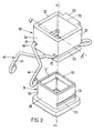
- les figures 2 et 3 sont des vues en perspective avant et arrière du montage du corps de la valve gaz (dont seule la partie inférieure a été représentée) sur le couvercle de la valve eau (également partiellement représentée) ; et
- la figure 4 est une vue en perspective du fil métallique utilisé dans la liaison représentée aux figures 2 et 3.
- Figure 1 is a longitudinal sectional view of a hot water generator which is equipped with a removable connection of the gas valve on the water valve according to the present invention;
- Figures 2 and 3 are front and rear perspective views of the mounting of the body of the gas valve (of which only the lower part has been shown) on the cover of the water valve (also partially shown); and
- FIG. 4 is a perspective view of the metal wire used in the connection shown in FIGS. 2 and 3.
A la figure 1 est représenté, de manière connue en
soi, un générateur d'eau chaude 1 fonctionnant au gaz qui
comprend un circuit d'entrée d'eau froide 2, une conduite de
sortie d'eau chaude 3, un échangeur de chaleur 4 interposé
entre le circuit d'entrée d'eau froide 2 et la conduite de
sortie d'eau chaude 3 et un brûleur 5 à combustible fluide
(notamment du gaz) qui transfère de la chaleur vers un
échangeur de chaleur 4.In Figure 1 is shown, in a manner known in
itself, a gas-fired hot water generator 1 which
includes a cold water inlet circuit 2, a
hot water outlet 3, a
Le gaz est amené au brûleur 5 au moyen d'une
conduite d'admission 6 dans laquelle le débit de gaz est
régulé par une valve gaz 7 dont l'ouverture et la fermeture
est commandée par un dispositif d'asservissement 8 de
l'admission du gaz au brûleur 5 au passage de l'eau froide
dans le circuit d'entrée d'eau froide 2 Ce dispositif 8
comprend une valve eau 9. The gas is brought to the
La valve gaz 7 est constituée d'un clapet 11
sollicité par un ressort de compression 12 pour venir en
appui contre un siège de clapet 13. Le ressort de
compression 12 est en appui sur le clapet 11 d'une part et
sur un épaulement 14 de la conduite d'admission 6 d'autre
part. Le clapet 11 est par ailleurs relié à une tige de
clapet 15 qui traverse le corps 16 de la valve gaz 7.The gas valve 7 consists of a
La valve eau 9 est constituée d'un plateau 20 qui
est monté en contact d'une membrane souple 21 elle-même
sensible au débit d'eau admis dans le circuit d'entrée d'eau
froide 2. Le plateau 20 est solidaire d'une tige 22 qui
traverse un couvercle 23 de la valve eau 9 pour être relié à
la tige de clapet 15 de la valve gaz 6.The
Généralement, le générateur d'eau chaude 1 est monté
verticalement de sorte que le corps 16 de la valve gaz 6 est
situé au-dessus du couvercle 23 de la valve eau 9 et les
tiges 15 et 22 sont sensiblement verticales et définissent
un axe longitudinal X-X.Generally, the hot water generator 1 is mounted
vertically so that the
L'étanchéité du montage de la tige 15 du clapet 11
dans le corps 16 de la valve gaz 6 est assurée au moyen d'un
joint torique 17 placé dans l'alésage dans lequel se déplace
la tige 15 tandis que l'étanchéité du couvercle 23 de la
valve eau 9 est assurée au moyen d'un joint torique 24 placé
dans l'orifice traversant ledit couvercle et dans lequel se
déplace la tige 22 du plateau 20.The tightness of the mounting of the
Le montage du corps 16 de la valve gaz 6 sur le
couvercle 23 de la valve eau 9 se fait par emboítement de la
partie inférieure 30 du corps 16 sur un organe de réception
31 venu de matière avec le dessus du couvercle 23 de la
valve eau 9.The mounting of the
Comme cela est plus particulièrement représenté aux
figures 2 et 3, la partie inférieure 30 de la valve gaz 6 et
l'organe de réception 31 de la valve eau 9 sont des
cylindres à base carrée d'axe longitudinal X-X et qui
peuvent être emboítés l'un sur l'autre.As is more particularly represented in
Figures 2 and 3, the
La partie inférieure 30 possède ainsi deux faces
latérales 32, 33 situées sensiblement en vis-à-vis ainsi
qu'une face avant 34 et une face arrière 35. De même,
l'organe de réception 31 possède deux faces latérales 36, 37
ainsi qu'une face avant 38 et une face arrière 39.The
L'emmanchement de la partie inférieure 30 sur
l'organe de réception 31 est maintenu en position de manière
non permanente au moyen d'un clip ou fil en matériau à
déformation élastique 40 de forme générale en "U" dont
l'ouverture est commandée par un opérateur.The fitting of the
Le fil en matériau à déformation élastique 40 est
plus particulièrement représenté à la figure 4 et est
constitué d'un fond 41 à partir duquel sont venues de
matière deux branches 42 et 43 qui sont sensiblement
parallèles et qui possèdent chacune une extrémité libre 44,
45.The wire of
Afin de faciliter la déformation élastique du fil
40, le fond 41 est relié aux deux branches 42 et 43 par deux
boucles ouvertes 46, 47. La forme des boucles est telle que
les extrémités des branches 42, 43 reliées aux boucles 46,
47 sont situées respectivement au niveau des extrémités du
fond 41 reliées aux boucles 46,47. Ainsi, lors de leur
écartement, les branches 42, 43 effectuent une rotation
autour d'un centre de rotation fictif situé sensiblement au
centre des boucles, de sorte que les branches 42, 43 se
déplacent pratiquement parallèlement à elles-mêmes.To facilitate elastic deformation of the
Afin qu'un opérateur puisse commander l'écartement
des branches 42 et 43, les extrémités libres 44, 45 de ces
branches sont croisées et repliées l'une vers l'autre à mi-longueur
de manière à être divergentes.So that an operator can control the
Le fond 41 et les deux branches 42, 43 sont situés
dans un même plan tandis que les parties repliées des
extrémités 44, 45 sont inclinées vers le bas. Au repos, la
valeur de l'écartement entre les parties repliées des
extrémités libres 44, 45 est suffisante pour que les
branches 42, 43 puissent être écartées d'une valeur au moins
égale à la dimension de la face avant 38 du corps 31.The
Le fil 40 est porté, préalablement à l'emmanchement
sur l'organe de réception 31, par la partie inférieure 30
sensiblement perpendiculairement à l'axe longitudinal X-X. A
cet effet, les faces latérales 32, 33 de la partie 30 sont
traversées par deux rainures 50, 51 dans lesquelles sont
logées les branches 42, 43 du fil 40. Le fond 41 de ce fil
est en butée entre la face arrière 35 et une patte 60 venue
de matière avec la partie supérieure de cette face et
parallèlement à celle-ci. La patte 60 et la face 35 forme
ainsi un passage 61 ouvert vers le bas et traversé par le
fond 41.The
Pour mettre en position le fil 40 sur la partie
inférieure 30, il suffit d'écarter l'une de l'autre les
branches 42 et 43 de manière à pouvoir enfiler le fil 40 en
forme de "U" sur l'une des faces latérales 32 et 33, jusqu'à
ce que le fond 41 vienne en butée entre la face arrière 35
et la patte 60, puis sur l'autre de ces faces. Les branches
42 et 43 sont alors relâchées et prennent place à
l'intérieur des rainures 50 et 51. Les extrémités libres 44
et 45 du fil 40 font saillie en avant de la face avant 34 de
la partie inférieure 30. La longueur de ces extrémités est
sensiblement égale à la largeur des faces 32, 33 de sorte
qu'un opérateur peut pincer ces extrémités tout en étant
éloigné de la partie inférieure 30. Par ailleurs, les
rainures 50, 51 sont ménagées en partie basse des faces
latérales 32, 33.To position the
Les faces latérales 36, 37 de l'organe de réception
31 sont munies de deux gorges 55, 56. En partie supérieure,
les faces latérales 36, 37, avant 38 et arrière 39 sont
biseautées.The lateral faces 36, 37 of the receiving
Lors de l'emmanchement de la partie inférieure 30
sur l'organe de réception 31, les branches 42, 43 sont
légèrement écartées l'une de l'autre en coopérant avec la
forme biseautée des faces latérales de l'organe 31. Ces
branches 42, 43 glissent ensuite le long des faces latérales
36, 37 pour ensuite s'encliqueter dans les gorges 55, 56. Le
corps 31 est alors immobilisé précisément sur l'organe de
réception 31, ce qui permet une immobilisation positive du
corps 16 de la valve gaz 6 sur le couvercle 23 de la valve
eau 9.When fitting the
Lorsqu'un opérateur veut procéder au démontage des
deux valves, il suffit de pincer les extrémités libres 44,
45 de manière à les rapprocher et à ainsi écarter les
branches 42, 43 pour les désengager des gorges 55, 56
appartenant aux faces latérales 36, 37 de l'organe de
réception 31. La forme des boucles 46, 47 permet d'écarter
les branches 42, 43 sur toute leur longueur. La partie
inférieure 30 peut alors être retirée de l'organe de
réception 31, ou vice-versa. La longueur des extrémités
libres 44,45 permet à l'opérateur de commander manuellement
à distance l'écartement des branches 42,43, sans être gêné
par la proximité immédiate d'autres parties constitutives du
générateur d'eau chaude. Après désolidarisation des deux
valves, le fil métallique 40 reste en place sur la partie
inférieure 30 du corps 16 de la valve gaz 6. When an operator wants to disassemble the
two valves, it suffices to pinch the free ends 44,
45 so as to bring them together and thus to draw aside the
L'immobilisation des valves l'une sur l'autre selon la présente invention est rendue d'autant plus efficace que l'étanchéité de l'ensemble est obtenue par d'autres parties constitutives de ces valves que celles participant au montage mécanique des valves.Immobilization of the valves one on the other according to the present invention is made all the more effective as the sealing of the assembly is obtained by other parts constituting these valves than those participating in the mechanical assembly of the valves.
Le corps de la valve gaz est par exemple réalisé en alliage de zinc tandis que le couvercle de la valve eau est réalisé en matériau composite.The gas valve body is for example made of zinc alloy while the water valve cover is made of composite material.
Par ailleurs, on comprend aisément que la partie
inférieure 30 et l'organe de réception 31 peuvent être, en
section transversale, de toute autre forme que celle décrite
précédemment, comme par exemple être de forme polygonale ou
circulaire. Les branches 42, 43 du fil en matériau à
déformation élastique 40 sont alors adoptées à la forme des
faces de la partie inférieure 30 sur laquelle elles sont
montées.Furthermore, it is easy to understand that the part
lower 30 and the receiving
Des éléments différents des valves eau et gaz peuvent être immobilisés au moyen du fil décrit ci-dessus.Different elements of the water and gas valves can be immobilized by means of the wire described above.
Claims (8)
Applications Claiming Priority (2)
| Application Number | Priority Date | Filing Date | Title |
|---|---|---|---|
| FR9812372 | 1998-10-02 | ||
| FR9812372A FR2784146B1 (en) | 1998-10-02 | 1998-10-02 | REMOVABLE CONNECTION BY PLUGGING OF A BODY ON A RECEPTION UNIT |
Publications (2)
| Publication Number | Publication Date |
|---|---|
| EP0990807A1 true EP0990807A1 (en) | 2000-04-05 |
| EP0990807B1 EP0990807B1 (en) | 2003-05-14 |
Family
ID=9531136
Family Applications (1)
| Application Number | Title | Priority Date | Filing Date |
|---|---|---|---|
| EP99402390A Expired - Lifetime EP0990807B1 (en) | 1998-10-02 | 1999-09-30 | Releasable connection for fitting a body on a receiving organ |
Country Status (7)
| Country | Link |
|---|---|
| EP (1) | EP0990807B1 (en) |
| AT (1) | ATE240462T1 (en) |
| DE (1) | DE69907842T2 (en) |
| ES (1) | ES2198864T3 (en) |
| FR (1) | FR2784146B1 (en) |
| HK (1) | HK1027151A1 (en) |
| PT (1) | PT990807E (en) |
Cited By (4)
| Publication number | Priority date | Publication date | Assignee | Title |
|---|---|---|---|---|
| DE102005037825B3 (en) * | 2005-08-08 | 2007-03-15 | Demag Cranes & Components Gmbh | Arrangement for the axial securing of a grooved pin |
| CN104653991A (en) * | 2013-11-22 | 2015-05-27 | 深圳富泰宏精密工业有限公司 | Fixedly holding device |
| CN111677735A (en) * | 2020-06-18 | 2020-09-18 | 沈阳远程摩擦密封材料有限公司 | Jump ring for powder metallurgy brake lining |
| CN111827795A (en) * | 2019-04-17 | 2020-10-27 | 茂旭资讯股份有限公司 | Magnetic lock structure with large tensile area |
Families Citing this family (1)
| Publication number | Priority date | Publication date | Assignee | Title |
|---|---|---|---|---|
| DE102005024258B4 (en) * | 2005-05-27 | 2013-01-31 | Continental Reifen Deutschland Gmbh | Arrangement for fixing an electronic component or a battery on the inside of a pneumatic vehicle tire |
Citations (4)
| Publication number | Priority date | Publication date | Assignee | Title |
|---|---|---|---|---|
| US4009896A (en) | 1976-05-10 | 1977-03-01 | General Motors Corporation | Quick connect coupling |
| DE3539020A1 (en) * | 1985-11-02 | 1987-05-07 | Bosch Gmbh Robert | Device for safeguarding against lack of water in an instantaneous water heater |
| US4733987A (en) * | 1986-02-27 | 1988-03-29 | Tomlinson Peter N | Spring clip |
| US5518332A (en) * | 1993-11-30 | 1996-05-21 | Nippon Cable System Inc. | End plate with clip |
-
1998
- 1998-10-02 FR FR9812372A patent/FR2784146B1/en not_active Expired - Fee Related
-
1999
- 1999-09-30 ES ES99402390T patent/ES2198864T3/en not_active Expired - Lifetime
- 1999-09-30 PT PT99402390T patent/PT990807E/en unknown
- 1999-09-30 AT AT99402390T patent/ATE240462T1/en not_active IP Right Cessation
- 1999-09-30 EP EP99402390A patent/EP0990807B1/en not_active Expired - Lifetime
- 1999-09-30 DE DE69907842T patent/DE69907842T2/en not_active Expired - Fee Related
-
2000
- 2000-10-04 HK HK00106286A patent/HK1027151A1/en not_active IP Right Cessation
Patent Citations (4)
| Publication number | Priority date | Publication date | Assignee | Title |
|---|---|---|---|---|
| US4009896A (en) | 1976-05-10 | 1977-03-01 | General Motors Corporation | Quick connect coupling |
| DE3539020A1 (en) * | 1985-11-02 | 1987-05-07 | Bosch Gmbh Robert | Device for safeguarding against lack of water in an instantaneous water heater |
| US4733987A (en) * | 1986-02-27 | 1988-03-29 | Tomlinson Peter N | Spring clip |
| US5518332A (en) * | 1993-11-30 | 1996-05-21 | Nippon Cable System Inc. | End plate with clip |
Cited By (6)
| Publication number | Priority date | Publication date | Assignee | Title |
|---|---|---|---|---|
| DE102005037825B3 (en) * | 2005-08-08 | 2007-03-15 | Demag Cranes & Components Gmbh | Arrangement for the axial securing of a grooved pin |
| US7568855B2 (en) | 2005-08-08 | 2009-08-04 | Demag Cranes & Components Gmbh | Arrangement for axial securing of grooved bolt |
| CN104653991A (en) * | 2013-11-22 | 2015-05-27 | 深圳富泰宏精密工业有限公司 | Fixedly holding device |
| CN104653991B (en) * | 2013-11-22 | 2019-03-01 | 深圳富泰宏精密工业有限公司 | Holding unit |
| CN111827795A (en) * | 2019-04-17 | 2020-10-27 | 茂旭资讯股份有限公司 | Magnetic lock structure with large tensile area |
| CN111677735A (en) * | 2020-06-18 | 2020-09-18 | 沈阳远程摩擦密封材料有限公司 | Jump ring for powder metallurgy brake lining |
Also Published As
| Publication number | Publication date |
|---|---|
| FR2784146B1 (en) | 2000-12-01 |
| PT990807E (en) | 2003-09-30 |
| DE69907842T2 (en) | 2004-02-19 |
| DE69907842D1 (en) | 2003-06-18 |
| FR2784146A1 (en) | 2000-04-07 |
| ES2198864T3 (en) | 2004-02-01 |
| EP0990807B1 (en) | 2003-05-14 |
| HK1027151A1 (en) | 2001-01-05 |
| ATE240462T1 (en) | 2003-05-15 |
Similar Documents
| Publication | Publication Date | Title |
|---|---|---|
| EP1165426B1 (en) | Device for filling receptacles fitted with an integrated cleaning device | |
| CH671816A5 (en) | ||
| CA2715750A1 (en) | Female quick-coupling device and quick coupling incorporating such a device | |
| EP0990807B1 (en) | Releasable connection for fitting a body on a receiving organ | |
| EP0396479B1 (en) | Spherical plug valve | |
| FR2707722A1 (en) | Rotary valve. | |
| FR2716517A1 (en) | Rotary valve. | |
| FR2742206A1 (en) | Stopcock especially for water hydrant giving rapid interruption of water flow | |
| EP0713047B1 (en) | Device for interrupting the flow in a fluid conveying pipe | |
| CA2261366C (en) | Individual drinking fountain with multidirectional connection of the type comprising a basin, valves and fittings | |
| EP1467842B1 (en) | Compressed gas cartridge for fixing apparatus with sealing integrated connection | |
| FR2761974A1 (en) | Anti-return valve for motor vehicle fuel pipe | |
| FR2523256A1 (en) | Three-port non-return valve - has two inlets each with spring loaded valve in opposition | |
| FR2654189A1 (en) | Condensate bleeding device for a steam distributing plant | |
| FR2509827A1 (en) | PRESSURE CONTROL VALVE | |
| EP2228137A1 (en) | Protective casing for a device designed to be placed near the floor, in particular for an automatic sprinkler | |
| FR2502727A1 (en) | SEALING DEVICE IN A GALETTE OR DRAWER TAP | |
| FR2616513A1 (en) | External tap for connecting onto a buried pipeline | |
| EP0591087B1 (en) | Cut-off device for gas conduits under low or mean pressure | |
| FR2652710A1 (en) | Irrigation hydrant with a device for maintaining the upstream pressure | |
| EP0557144A1 (en) | Apparatus with reciprocatory positioning means of a shaft with a cylindrical housing | |
| FR2662467A1 (en) | Improved oil well head | |
| FR2721370A1 (en) | Automatic shut=off valve for excess flow | |
| EP0612005A1 (en) | Fluidpressure reducer with cannula calliper | |
| FR2827659A1 (en) | Ceramic disc cartridge valve for water mixer has fixed and movable ceramic discs with cavities controlling ports |
Legal Events
| Date | Code | Title | Description |
|---|---|---|---|
| PUAI | Public reference made under article 153(3) epc to a published international application that has entered the european phase |
Free format text: ORIGINAL CODE: 0009012 |
|
| AK | Designated contracting states |
Kind code of ref document: A1 Designated state(s): AT BE CH CY DE DK ES FI FR GB GR IE IT LI LU MC NL PT SE |
|
| AX | Request for extension of the european patent |
Free format text: AL;LT;LV;MK;RO;SI |
|
| 17P | Request for examination filed |
Effective date: 20000327 |
|
| AKX | Designation fees paid |
Free format text: AT BE CH CY DE DK ES FI FR GB GR IE IT LI LU MC NL PT SE |
|
| GRAH | Despatch of communication of intention to grant a patent |
Free format text: ORIGINAL CODE: EPIDOS IGRA |
|
| GRAH | Despatch of communication of intention to grant a patent |
Free format text: ORIGINAL CODE: EPIDOS IGRA |
|
| GRAA | (expected) grant |
Free format text: ORIGINAL CODE: 0009210 |
|
| AK | Designated contracting states |
Designated state(s): AT BE CH CY DE DK ES FI FR GB GR IE IT LI LU MC NL PT SE |
|
| PG25 | Lapsed in a contracting state [announced via postgrant information from national office to epo] |
Ref country code: IE Free format text: LAPSE BECAUSE OF FAILURE TO SUBMIT A TRANSLATION OF THE DESCRIPTION OR TO PAY THE FEE WITHIN THE PRESCRIBED TIME-LIMIT Effective date: 20030514 Ref country code: FI Free format text: LAPSE BECAUSE OF FAILURE TO SUBMIT A TRANSLATION OF THE DESCRIPTION OR TO PAY THE FEE WITHIN THE PRESCRIBED TIME-LIMIT Effective date: 20030514 Ref country code: AT Free format text: LAPSE BECAUSE OF FAILURE TO SUBMIT A TRANSLATION OF THE DESCRIPTION OR TO PAY THE FEE WITHIN THE PRESCRIBED TIME-LIMIT Effective date: 20030514 |
|
| REG | Reference to a national code |
Ref country code: GB Ref legal event code: FG4D Free format text: NOT ENGLISH |
|
| REG | Reference to a national code |
Ref country code: CH Ref legal event code: EP |
|
| REG | Reference to a national code |
Ref country code: IE Ref legal event code: FG4D Free format text: FRENCH |
|
| REF | Corresponds to: |
Ref document number: 69907842 Country of ref document: DE Date of ref document: 20030618 Kind code of ref document: P |
|
| PG25 | Lapsed in a contracting state [announced via postgrant information from national office to epo] |
Ref country code: SE Free format text: LAPSE BECAUSE OF FAILURE TO SUBMIT A TRANSLATION OF THE DESCRIPTION OR TO PAY THE FEE WITHIN THE PRESCRIBED TIME-LIMIT Effective date: 20030814 Ref country code: GR Free format text: LAPSE BECAUSE OF FAILURE TO SUBMIT A TRANSLATION OF THE DESCRIPTION OR TO PAY THE FEE WITHIN THE PRESCRIBED TIME-LIMIT Effective date: 20030814 Ref country code: DK Free format text: LAPSE BECAUSE OF FAILURE TO SUBMIT A TRANSLATION OF THE DESCRIPTION OR TO PAY THE FEE WITHIN THE PRESCRIBED TIME-LIMIT Effective date: 20030814 |
|
| PG25 | Lapsed in a contracting state [announced via postgrant information from national office to epo] |
Ref country code: MC Free format text: LAPSE BECAUSE OF NON-PAYMENT OF DUE FEES Effective date: 20030930 Ref country code: LU Free format text: LAPSE BECAUSE OF NON-PAYMENT OF DUE FEES Effective date: 20030930 Ref country code: LI Free format text: LAPSE BECAUSE OF NON-PAYMENT OF DUE FEES Effective date: 20030930 Ref country code: CY Free format text: LAPSE BECAUSE OF FAILURE TO SUBMIT A TRANSLATION OF THE DESCRIPTION OR TO PAY THE FEE WITHIN THE PRESCRIBED TIME-LIMIT Effective date: 20030930 Ref country code: CH Free format text: LAPSE BECAUSE OF NON-PAYMENT OF DUE FEES Effective date: 20030930 Ref country code: BE Free format text: LAPSE BECAUSE OF NON-PAYMENT OF DUE FEES Effective date: 20030930 |
|
| REG | Reference to a national code |
Ref country code: PT Ref legal event code: SC4A Free format text: AVAILABILITY OF NATIONAL TRANSLATION Effective date: 20030723 |
|
| GBT | Gb: translation of ep patent filed (gb section 77(6)(a)/1977) | ||
| REG | Reference to a national code |
Ref country code: IE Ref legal event code: FD4D Ref document number: 0990807E Country of ref document: IE |
|
| REG | Reference to a national code |
Ref country code: ES Ref legal event code: FG2A Ref document number: 2198864 Country of ref document: ES Kind code of ref document: T3 |
|
| PLBE | No opposition filed within time limit |
Free format text: ORIGINAL CODE: 0009261 |
|
| STAA | Information on the status of an ep patent application or granted ep patent |
Free format text: STATUS: NO OPPOSITION FILED WITHIN TIME LIMIT |
|
| BERE | Be: lapsed |
Owner name: *CHAFFOTEAUX ET MAURY Effective date: 20030930 |
|
| 26N | No opposition filed |
Effective date: 20040217 |
|
| REG | Reference to a national code |
Ref country code: CH Ref legal event code: PL |
|
| PGFP | Annual fee paid to national office [announced via postgrant information from national office to epo] |
Ref country code: NL Payment date: 20040818 Year of fee payment: 6 |
|
| PGFP | Annual fee paid to national office [announced via postgrant information from national office to epo] |
Ref country code: DE Payment date: 20040908 Year of fee payment: 6 |
|
| PGFP | Annual fee paid to national office [announced via postgrant information from national office to epo] |
Ref country code: GB Payment date: 20050902 Year of fee payment: 7 |
|
| PG25 | Lapsed in a contracting state [announced via postgrant information from national office to epo] |
Ref country code: NL Free format text: LAPSE BECAUSE OF NON-PAYMENT OF DUE FEES Effective date: 20060401 Ref country code: DE Free format text: LAPSE BECAUSE OF NON-PAYMENT OF DUE FEES Effective date: 20060401 |
|
| NLV4 | Nl: lapsed or anulled due to non-payment of the annual fee |
Effective date: 20060401 |
|
| PGFP | Annual fee paid to national office [announced via postgrant information from national office to epo] |
Ref country code: PT Payment date: 20060823 Year of fee payment: 8 |
|
| PGFP | Annual fee paid to national office [announced via postgrant information from national office to epo] |
Ref country code: ES Payment date: 20060912 Year of fee payment: 8 |
|
| PGFP | Annual fee paid to national office [announced via postgrant information from national office to epo] |
Ref country code: IT Payment date: 20060930 Year of fee payment: 8 |
|
| GBPC | Gb: european patent ceased through non-payment of renewal fee |
Effective date: 20060930 |
|
| PG25 | Lapsed in a contracting state [announced via postgrant information from national office to epo] |
Ref country code: GB Free format text: LAPSE BECAUSE OF NON-PAYMENT OF DUE FEES Effective date: 20060930 |
|
| REG | Reference to a national code |
Ref country code: PT Ref legal event code: MM4A Free format text: LAPSE DUE TO NON-PAYMENT OF FEES Effective date: 20080331 |
|
| PG25 | Lapsed in a contracting state [announced via postgrant information from national office to epo] |
Ref country code: PT Free format text: LAPSE BECAUSE OF NON-PAYMENT OF DUE FEES Effective date: 20080331 |
|
| REG | Reference to a national code |
Ref country code: FR Ref legal event code: ST Effective date: 20080531 |
|
| PG25 | Lapsed in a contracting state [announced via postgrant information from national office to epo] |
Ref country code: FR Free format text: LAPSE BECAUSE OF NON-PAYMENT OF DUE FEES Effective date: 20071001 |
|
| PGFP | Annual fee paid to national office [announced via postgrant information from national office to epo] |
Ref country code: FR Payment date: 20060928 Year of fee payment: 8 |
|
| REG | Reference to a national code |
Ref country code: ES Ref legal event code: FD2A Effective date: 20071001 |
|
| PG25 | Lapsed in a contracting state [announced via postgrant information from national office to epo] |
Ref country code: ES Free format text: LAPSE BECAUSE OF NON-PAYMENT OF DUE FEES Effective date: 20071001 |
|
| PG25 | Lapsed in a contracting state [announced via postgrant information from national office to epo] |
Ref country code: IT Free format text: LAPSE BECAUSE OF NON-PAYMENT OF DUE FEES Effective date: 20070930 |