EP0990773A2 - Hydraulisches Spielausgleichselement mit einem Überdruckventil - Google Patents
Hydraulisches Spielausgleichselement mit einem Überdruckventil Download PDFInfo
- Publication number
- EP0990773A2 EP0990773A2 EP99306564A EP99306564A EP0990773A2 EP 0990773 A2 EP0990773 A2 EP 0990773A2 EP 99306564 A EP99306564 A EP 99306564A EP 99306564 A EP99306564 A EP 99306564A EP 0990773 A2 EP0990773 A2 EP 0990773A2
- Authority
- EP
- European Patent Office
- Prior art keywords
- plunger
- pressure chamber
- high pressure
- lash adjuster
- valve
- Prior art date
- Legal status (The legal status is an assumption and is not a legal conclusion. Google has not performed a legal analysis and makes no representation as to the accuracy of the status listed.)
- Withdrawn
Links
- 239000012530 fluid Substances 0.000 claims abstract description 48
- 238000002485 combustion reaction Methods 0.000 claims abstract description 10
- 239000010705 motor oil Substances 0.000 claims description 3
- 230000005484 gravity Effects 0.000 claims 1
- 230000001105 regulatory effect Effects 0.000 abstract 1
- 239000003921 oil Substances 0.000 description 4
- 238000004519 manufacturing process Methods 0.000 description 2
- 208000031872 Body Remains Diseases 0.000 description 1
- 230000003247 decreasing effect Effects 0.000 description 1
- 238000006073 displacement reaction Methods 0.000 description 1
- 230000000717 retained effect Effects 0.000 description 1
- 238000004904 shortening Methods 0.000 description 1
Images

Classifications
-
- F—MECHANICAL ENGINEERING; LIGHTING; HEATING; WEAPONS; BLASTING
- F01—MACHINES OR ENGINES IN GENERAL; ENGINE PLANTS IN GENERAL; STEAM ENGINES
- F01L—CYCLICALLY OPERATING VALVES FOR MACHINES OR ENGINES
- F01L1/00—Valve-gear or valve arrangements, e.g. lift-valve gear
- F01L1/20—Adjusting or compensating clearance
- F01L1/22—Adjusting or compensating clearance automatically, e.g. mechanically
- F01L1/24—Adjusting or compensating clearance automatically, e.g. mechanically by fluid means, e.g. hydraulically
- F01L1/2405—Adjusting or compensating clearance automatically, e.g. mechanically by fluid means, e.g. hydraulically by means of a hydraulic adjusting device located between the cylinder head and rocker arm
Definitions
- the present invention relates generally to hydraulic lash adjusters. More specifically, the present invention relates to a hydraulic lash adjuster for an internal combustion engine which incorporates a second check valve to provide a faster leak down of engine fluid when the engine exhaust valve is subjected to high forces.
- Hydraulic lash adjusters for internal combustion engines have been in use for many years. Hydraulic lash adjusters are used to eliminate clearance or lash between engine valve train components which occur under varying operating conditions, in order to maintain engine efficiency and to reduce noise and wear in the valve train.
- Hydraulic lash adjusters operate by transmitting the energy of the valve actuating cam through hydraulic fluid trapped in a pressure chamber beneath a plunger. During each operation of the cam, as the length of the valve actuating components vary due to temperature changes, small quantities of hydraulic fluid are permitted to enter or escape from the pressure chamber. As the hydraulic fluid enters or escapes the pressure chamber, the position of the plunger is adjusted and consequently the effective total length of the valve train is adjusted which minimises or eliminates the lash.
- a hydraulic lash adjuster for an internal combustion engine including a body having a bore formed therein.
- a plunger is slidingly received within the bore of the lash adjuster body.
- the lash adjuster has a high pressure chamber formed between the bottom of the first bore and the plunger.
- the plunger has a fluid chamber formed therein which is in communication with an inlet opening for supplying engine fluid thereto.
- a first valve opening in the plunger provides fluid communication between the fluid chamber and the high pressure chamber.
- a first check valve element is positioned within the body to selectively open or close the first valve opening in response to any pressure difference between the fluid chamber and the high pressure chamber.
- a leak path between the lash adjuster body and the plunger allows fluid to leak from the high pressure chamber due to increased force on the plunger.
- a second valve opening is located in the bottom of the first bore and is in communication with a second check valve for allowing fluid to leak from the high pressure chamber at an increase rate in response to increased force on the plunger.
- a further advantage of the present invention is that it provides a lash adjuster that can compensate for increased force on the lash adjuster plunger by releasing oil from the lash adjuster high pressure chamber through a second check valve mechanism.
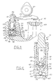
- Figures 1 through 4 illustrate a preferred embodiment of a lash adjuster in accordance with the present invention.
- Figure 1 illustrates the lash adjuster with the engine valve 52 closed while
- Figure 2 illustrates the lash adjuster when the engine valve 52 is open.
- Figure 3 illustrates the lash adjuster when the engine valve 52 is almost closed.
- Figure 4 is an enlarged cross-sectional illustration of a lash adjuster.
- the lash adjuster 10 includes a body member 12 in which a bore 14 is formed. The bottom of the bore 14 is defined by surface 16.
- a plunger 18 is telescopically positioned within the bore 14, such that the plunger 18 can move with respect to the body member 12.
- the plunger 18 is preferably in communication with a valve actuated cam 20 through a cam follower 22 which limits the motion of the plunger 18 away from surface 16.
- the plunger 18 is machined such that a normal leak path 24 is formed between the outer diameter of the plunger 18 and the inner diameter of the bore 14.
- the plunger 18 has a fluid chamber 26 formed therein for receiving an engine fluid, such as oil or the like, through a fluid inlet passage 28.
- the fluid chamber 26 has a first valve opening 30 preferably formed through its bottom surface 32. The first valve opening 30 allows engine fluid from the fluid chamber 26 to flow to a high pressure chamber 34 defined by the area between the bottom surface 32 of the plunger 18, the bottom bore surface 16 and the inner diameter of the lash adjuster body 12.
- the high pressure chamber 34 has a first check valve 36 which regulates the flow of engine fluid from the fluid chamber 26 through the first valve opening 30 and to the high pressure chamber 34.
- the first check valve 36 preferably includes a ball valve member 38 which has a diameter sufficient to seal off the first valve opening 30.
- the ball valve member 38 is preferably biased by a spring member 40 into a closed position wherein the first check valve 36 is closed and engine fluid is prevented from flowing out of the high pressure chamber 34.
- the spring member 40 is supported on a platform member 42 which is held in contact with the bottom surface 32 of the plunger 18 by spring member 44.
- the first check valve 36 will travel up and down as the plunger 18 is moved within the lash adjuster body 12 toward and away from the bottom bore surface 16. It should be understood that any other valve arrangement that allows for the selective engagement with the first valve opening 30 described above may instead be utilised in accordance with the present invention.
- Plunger spring member 44 is positioned in the high pressure chamber 34 between the bottom bore surface 16 and the bottom surface 32 of the plunger 18.
- the plunger spring 44 biases the plunger 18 away from surface 16 causing the plunger 18 to move when there is no force on its top portion 46 thus eliminating any lash in the valve or valve train components.
- the high pressure chamber 34 includes a second valve opening 50 for relieving pressure in the high pressure chamber 34 when it exceeds a certain level. Since leak path 24 has a limited size, it can only accommodate the leak down of a limited rate of engine oil, which is often not sufficient to compensate for the growth rate of the engine valve 52 during engine warm up after a cold start.
- the second valve opening 50 allows the leak down rate of engine fluid to be increased when the engine valve 52 is not properly closed during a combustion event.
- a second check valve 54 is in communication with the second valve opening 50.
- the second check valve 54 preferably includes a ball member 56 with a diameter large enough to seal off the second valve opening 50.
- the ball member 56 is biased into a closed position ( Figures 1 and 2) preventing engine fluid from flowing through the second valve opening 50 by a leaf spring 58 or the like.
- the leaf spring 58 is preferably retained about its periphery 60 in a groove 62 formed in the inner diameter of the lash adjuster body 12.
- the cam operating cycle comprises two distinct events: a base circle event and a valve actuation event.
- the base circle event is characterised by a constant radius between the cam centre of rotation and the cam follower 22 during which effectively no cam energy is transmitted.
- the valve actuation event is characterised by a varying radius between the cam centre of rotation and the cam follower 22 which effectively transmits cam energy to open and close the engine valve 52.
- the lash adjuster 10 During the valve actuation event, a portion of the loads due to the valve spring, the inertia of the valve train components, and the cylinder pressure are transmitted through the valve train to the lash adjuster 10.
- the load acts on the plunger 18 and raises the pressure of the hydraulic fluid within the lash adjuster high pressure chamber 34 in proportion to the plunger area causing some fluid to escape through the normal leak path 24. As the fluid escapes, the plunger 18 moves down according to the change in volume of the high pressure chamber 34, shortening the effective length of the valve train.
- the lash adjuster plunger spring 44 biases and moves the plunger 18 upwardly away from surface 16 such that no clearance or lash exists between the valve actuation components. Hydraulic fluid is drawn into the high pressure chamber 34 through the first check valve 36 in response to the increased volume of the high pressure chamber 34 as the plunger 18 moves up. If the effective length of the valve train shortens during the cam cycle, positive lash is created and the lash adjuster extends, moving the plunger 18 to a higher position at the end of the cycle than at the beginning. Inversely, as shown in Figure 3, if the effective length of the valve train lengthens during the cam cycle, negative lash is created and the lash adjuster contracts, moving the plunger 18 to a lower position at the end of the cycle than at the beginning.
- the pressure in the high pressure chamber will exceed a predetermined level during each combustion event and the normally closed second check valve 54 is moved to an open position, as shown in Figure 3.
- the second check valve 54 is moved against the force of the spring 58 allowing engine fluid to pass through the second valve opening 50 and into the engine sump (not shown).
- the force of the spring 58 biases the ball member 56 back into engagement with the second valve opening 50 ( Figures 1 and 2), thereby closing the second check valve 54.
- a passageway 66 is in communication with the second valve opening 50 allowing engine fluid that passes therethrough to exit the lash adjuster body 12 and drain to the engine sump.
Landscapes
- Engineering & Computer Science (AREA)
- Mechanical Engineering (AREA)
- General Engineering & Computer Science (AREA)
- Valve-Gear Or Valve Arrangements (AREA)
Applications Claiming Priority (2)
| Application Number | Priority Date | Filing Date | Title |
|---|---|---|---|
| US138742 | 1998-08-24 | ||
| US09/138,742 US5931132A (en) | 1998-08-24 | 1998-08-24 | Hydraulic lash adjuster with pressure relief check valve |
Publications (2)
| Publication Number | Publication Date |
|---|---|
| EP0990773A2 true EP0990773A2 (de) | 2000-04-05 |
| EP0990773A3 EP0990773A3 (de) | 2000-05-24 |
Family
ID=22483429
Family Applications (1)
| Application Number | Title | Priority Date | Filing Date |
|---|---|---|---|
| EP99306564A Withdrawn EP0990773A3 (de) | 1998-08-24 | 1999-08-19 | Hydraulisches Spielausgleichselement mit einem Überdruckventil |
Country Status (2)
| Country | Link |
|---|---|
| US (1) | US5931132A (de) |
| EP (1) | EP0990773A3 (de) |
Families Citing this family (6)
| Publication number | Priority date | Publication date | Assignee | Title |
|---|---|---|---|---|
| EP1451623B1 (de) * | 2001-12-06 | 2006-09-06 | Diamould Ltd | Dichtungssystem für optische stecker |
| US7007708B2 (en) * | 2003-10-17 | 2006-03-07 | Delphi Techonologies, Inc. | Flow control valve |
| DE102004018386A1 (de) * | 2004-04-16 | 2005-11-03 | Ina-Schaeffler Kg | Verfahren zum Einstellen des Kugelhubs eines Ventilspielausgleichselements |
| USD706084S1 (en) | 2012-06-19 | 2014-06-03 | Sistema Plastics Limited | Lidded container |
| USD704503S1 (en) | 2012-06-19 | 2014-05-13 | Sistema Plastics Limited | Lid for a container |
| GB2503705A (en) * | 2012-07-05 | 2014-01-08 | Eaton Srl | Hydraulic Lash Adjuster and Lost Motion System |
Family Cites Families (26)
| Publication number | Priority date | Publication date | Assignee | Title |
|---|---|---|---|---|
| US3273548A (en) * | 1965-09-29 | 1966-09-20 | Gen Motors Corp | Hydraulic lash adjuster |
| US3587539A (en) * | 1970-04-17 | 1971-06-28 | Johnson Products Inc | Hydraulic lash adjuster |
| US3805753A (en) * | 1972-02-24 | 1974-04-23 | Johnson Products Inc | Hydraulic lash adjuster for overhead cam engines |
| US3799129A (en) * | 1972-11-06 | 1974-03-26 | Johnson Products Inc | Hydraulic lash adjuster oil metering means |
| US4098240A (en) * | 1975-02-18 | 1978-07-04 | Eaton Corporation | Valve gear and lash adjustment means for same |
| US4004558A (en) * | 1975-09-02 | 1977-01-25 | General Motors Corporation | Hydraulic lash adjuster oil metering valve |
| JPS56124615A (en) * | 1980-03-06 | 1981-09-30 | Aisin Seiki Co Ltd | Rush adjuster device |
| US4407241A (en) * | 1980-12-31 | 1983-10-04 | Cummins Engine Company, Inc. | Expandable hydraulic tappet with a variable exit valve |
| US4462364A (en) * | 1981-09-17 | 1984-07-31 | Aisin Seiki Kabushiki Kaisha | Hydraulic lash adjuster |
| US4481913A (en) * | 1982-12-20 | 1984-11-13 | General Motors Corporation | Hydraulic lash adjuster oil metering ball valve |
| JPS59175615U (ja) * | 1983-05-13 | 1984-11-24 | アイシン精機株式会社 | 可変気筒用油圧リフタ |
| US4589383A (en) * | 1983-06-09 | 1986-05-20 | Automotive Engine Associates | Squeeze film rocker tip |
| US4596213A (en) * | 1985-06-20 | 1986-06-24 | Eaton Corporation | Cap retainer for hydraulic lash adjuster assembly |
| US4633827A (en) * | 1985-10-07 | 1987-01-06 | Eaton Corporation | Hydraulic lash adjuster with combined reservoir extension and metering system |
| DE3635110A1 (de) * | 1985-10-15 | 1987-04-16 | Honda Motor Co Ltd | Ventilsteuereinrichtung fuer eine brennkraftmaschine |
| JPS63170509A (ja) * | 1987-10-23 | 1988-07-14 | Nippon Seiko Kk | 油圧式ラッシュアジャスタ |
| DE3800945C1 (de) * | 1988-01-15 | 1989-02-16 | Daimler-Benz Ag, 7000 Stuttgart, De | |
| JPH01232103A (ja) * | 1988-03-12 | 1989-09-18 | Mazda Motor Corp | エンジンのバルブ駆動装置 |
| JPH0717765Y2 (ja) * | 1988-10-29 | 1995-04-26 | 富士重工業株式会社 | 油圧式ハイドロリックラッシュアジャスタ装置 |
| US4977867A (en) * | 1989-08-28 | 1990-12-18 | Rhoads Jack L | Self-adjusting variable duration hydraulic lifter |
| US5361733A (en) * | 1993-01-28 | 1994-11-08 | General Motors Corporation | Compact valve lifters |
| US5372114A (en) * | 1993-10-29 | 1994-12-13 | Cummins Engine Company, Inc. | Dampened pressure regulating and load cell tappet |
| US5660153A (en) * | 1995-03-28 | 1997-08-26 | Eaton Corporation | Valve control system |
| JPH08284620A (ja) * | 1995-04-17 | 1996-10-29 | Mitsubishi Motors Corp | ラッシュアジャスタ及びラッシュアジャスタを備えた内燃機関 |
| US5623898A (en) * | 1996-01-16 | 1997-04-29 | Bruton; Murl L. | Variable duration hydraulic valve lifters |
| US5622147A (en) * | 1996-03-08 | 1997-04-22 | Eaton Corporation | Hydraulic lash adjuster |
-
1998
- 1998-08-24 US US09/138,742 patent/US5931132A/en not_active Expired - Fee Related
-
1999
- 1999-08-19 EP EP99306564A patent/EP0990773A3/de not_active Withdrawn
Also Published As
| Publication number | Publication date |
|---|---|
| EP0990773A3 (de) | 2000-05-24 |
| US5931132A (en) | 1999-08-03 |
Similar Documents
| Publication | Publication Date | Title |
|---|---|---|
| EP0794322B1 (de) | Hydraulisches Ventilspielausgleichselement | |
| EP1298287B1 (de) | Hydraulisches Ventilspielausgleichselement & normalerweise geöffnetes Regelventil dafür | |
| US6474277B1 (en) | Method and apparatus for valve seating velocity control | |
| JP4596643B2 (ja) | 制限式ロストモーション・タペットの弁着座速度制限装置 | |
| US7543555B2 (en) | Hydraulic lash compensation device with mechanical lift loss feature | |
| EP1113147B1 (de) | Hydraulisches Spielausgleichselement | |
| US4098240A (en) | Valve gear and lash adjustment means for same | |
| EP1571300A2 (de) | Hydraulisches Ventilspielausgleichselement mit doppeltem Ölzufuhr | |
| JP2001132418A (ja) | 内燃機関 | |
| US20090078225A1 (en) | Switchable rocker arm | |
| US5862785A (en) | Hydraulic lash adjuster and improved oil flow path therefor | |
| US6318324B1 (en) | Sealed hydraulic lifter for extreme angle operation | |
| US5967105A (en) | Hydraulic lash adjuster with an open ended top plunger surface | |
| US5931132A (en) | Hydraulic lash adjuster with pressure relief check valve | |
| CN1240497A (zh) | 内燃机气门机构挺杆 | |
| US7121523B2 (en) | Fluid control valve | |
| EP0953734B1 (de) | Hydraulisches Spielausgleichselement und Rückschlagventil dafür | |
| EP0985805A2 (de) | Hydraulisches Ventilspielausgleichselement | |
| US6021751A (en) | Hydraulic valve lifter with lash | |
| US7421994B2 (en) | Hydraulic lash adjuster having a check valve cartridge sub-assembly | |
| JP4176031B2 (ja) | 内燃機関の可変動弁装置 | |
| KR20010042444A (ko) | 압축 해제 브레이크를 구비한 유압식 래시 조정기 | |
| US7237520B2 (en) | Hydraulic valve-lash-adjusting element (HVA) | |
| EP1111199A2 (de) | Hydraulisches Spielausgleichselement | |
| US5964193A (en) | Synchronous hydraulic lash adjuster |
Legal Events
| Date | Code | Title | Description |
|---|---|---|---|
| PUAI | Public reference made under article 153(3) epc to a published international application that has entered the european phase |
Free format text: ORIGINAL CODE: 0009012 |
|
| AK | Designated contracting states |
Kind code of ref document: A2 Designated state(s): DE FR GB |
|
| AX | Request for extension of the european patent |
Free format text: AL;LT;LV;MK;RO;SI |
|
| PUAL | Search report despatched |
Free format text: ORIGINAL CODE: 0009013 |
|
| AK | Designated contracting states |
Kind code of ref document: A3 Designated state(s): AT BE CH CY DE DK ES FI FR GB GR IE IT LI LU MC NL PT SE |
|
| AX | Request for extension of the european patent |
Free format text: AL;LT;LV;MK;RO;SI |
|
| 17P | Request for examination filed |
Effective date: 20001012 |
|
| AKX | Designation fees paid |
Free format text: DE FR GB |
|
| STAA | Information on the status of an ep patent application or granted ep patent |
Free format text: STATUS: THE APPLICATION HAS BEEN WITHDRAWN |
|
| 18W | Application withdrawn |
Withdrawal date: 20010709 |