EP0990531A1 - Tintenstrahldrucker mit einer Einrichtung zur Kompensation der Flugzeitsvariation der Tintentröpfen - Google Patents
Tintenstrahldrucker mit einer Einrichtung zur Kompensation der Flugzeitsvariation der Tintentröpfen Download PDFInfo
- Publication number
- EP0990531A1 EP0990531A1 EP99117655A EP99117655A EP0990531A1 EP 0990531 A1 EP0990531 A1 EP 0990531A1 EP 99117655 A EP99117655 A EP 99117655A EP 99117655 A EP99117655 A EP 99117655A EP 0990531 A1 EP0990531 A1 EP 0990531A1
- Authority
- EP
- European Patent Office
- Prior art keywords
- pen
- ink
- carriage
- axis
- flight time
- Prior art date
- Legal status (The legal status is an assumption and is not a legal conclusion. Google has not performed a legal analysis and makes no representation as to the accuracy of the status listed.)
- Granted
Links
Images


Classifications
-
- B—PERFORMING OPERATIONS; TRANSPORTING
- B41—PRINTING; LINING MACHINES; TYPEWRITERS; STAMPS
- B41J—TYPEWRITERS; SELECTIVE PRINTING MECHANISMS, i.e. MECHANISMS PRINTING OTHERWISE THAN FROM A FORME; CORRECTION OF TYPOGRAPHICAL ERRORS
- B41J2/00—Typewriters or selective printing mechanisms characterised by the printing or marking process for which they are designed
- B41J2/005—Typewriters or selective printing mechanisms characterised by the printing or marking process for which they are designed characterised by bringing liquid or particles selectively into contact with a printing material
- B41J2/01—Ink jet
- B41J2/07—Ink jet characterised by jet control
-
- B—PERFORMING OPERATIONS; TRANSPORTING
- B41—PRINTING; LINING MACHINES; TYPEWRITERS; STAMPS
- B41J—TYPEWRITERS; SELECTIVE PRINTING MECHANISMS, i.e. MECHANISMS PRINTING OTHERWISE THAN FROM A FORME; CORRECTION OF TYPOGRAPHICAL ERRORS
- B41J2/00—Typewriters or selective printing mechanisms characterised by the printing or marking process for which they are designed
- B41J2/005—Typewriters or selective printing mechanisms characterised by the printing or marking process for which they are designed characterised by bringing liquid or particles selectively into contact with a printing material
- B41J2/01—Ink jet
- B41J2/015—Ink jet characterised by the jet generation process
- B41J2/04—Ink jet characterised by the jet generation process generating single droplets or particles on demand
- B41J2/045—Ink jet characterised by the jet generation process generating single droplets or particles on demand by pressure, e.g. electromechanical transducers
- B41J2/04501—Control methods or devices therefor, e.g. driver circuits, control circuits
- B41J2/04503—Control methods or devices therefor, e.g. driver circuits, control circuits aiming at compensating carriage speed
-
- B—PERFORMING OPERATIONS; TRANSPORTING
- B41—PRINTING; LINING MACHINES; TYPEWRITERS; STAMPS
- B41J—TYPEWRITERS; SELECTIVE PRINTING MECHANISMS, i.e. MECHANISMS PRINTING OTHERWISE THAN FROM A FORME; CORRECTION OF TYPOGRAPHICAL ERRORS
- B41J19/00—Character- or line-spacing mechanisms
- B41J19/18—Character-spacing or back-spacing mechanisms; Carriage return or release devices therefor
- B41J19/20—Positive-feed character-spacing mechanisms
- B41J19/202—Drive control means for carriage movement
-
- B—PERFORMING OPERATIONS; TRANSPORTING
- B41—PRINTING; LINING MACHINES; TYPEWRITERS; STAMPS
- B41J—TYPEWRITERS; SELECTIVE PRINTING MECHANISMS, i.e. MECHANISMS PRINTING OTHERWISE THAN FROM A FORME; CORRECTION OF TYPOGRAPHICAL ERRORS
- B41J2/00—Typewriters or selective printing mechanisms characterised by the printing or marking process for which they are designed
- B41J2/005—Typewriters or selective printing mechanisms characterised by the printing or marking process for which they are designed characterised by bringing liquid or particles selectively into contact with a printing material
- B41J2/01—Ink jet
- B41J2/015—Ink jet characterised by the jet generation process
- B41J2/04—Ink jet characterised by the jet generation process generating single droplets or particles on demand
- B41J2/045—Ink jet characterised by the jet generation process generating single droplets or particles on demand by pressure, e.g. electromechanical transducers
- B41J2/04501—Control methods or devices therefor, e.g. driver circuits, control circuits
- B41J2/04573—Timing; Delays
-
- B—PERFORMING OPERATIONS; TRANSPORTING
- B41—PRINTING; LINING MACHINES; TYPEWRITERS; STAMPS
- B41J—TYPEWRITERS; SELECTIVE PRINTING MECHANISMS, i.e. MECHANISMS PRINTING OTHERWISE THAN FROM A FORME; CORRECTION OF TYPOGRAPHICAL ERRORS
- B41J2/00—Typewriters or selective printing mechanisms characterised by the printing or marking process for which they are designed
- B41J2/005—Typewriters or selective printing mechanisms characterised by the printing or marking process for which they are designed characterised by bringing liquid or particles selectively into contact with a printing material
- B41J2/01—Ink jet
- B41J2/015—Ink jet characterised by the jet generation process
- B41J2/04—Ink jet characterised by the jet generation process generating single droplets or particles on demand
- B41J2/045—Ink jet characterised by the jet generation process generating single droplets or particles on demand by pressure, e.g. electromechanical transducers
- B41J2/04501—Control methods or devices therefor, e.g. driver circuits, control circuits
- B41J2/04586—Control methods or devices therefor, e.g. driver circuits, control circuits controlling heads of a type not covered by groups B41J2/04575 - B41J2/04585, or of an undefined type
Definitions
- the present invention relates to ink-jet hard copy apparatus and, more particularly, to the art of generating control signals for firing ink droplets from a scanning ink-jet printhead and, specifically to methods and apparatus for compensating for variations in printhead-to-media spacing and printhead scanning velocity.
- ink-jet technology is relatively well developed.
- Commercial products such as computer printers, graphics plotters, copiers, and facsimile machines employ ink-jet technology for producing hard copy.
- the basics of this technology are disclosed, for example, in various articles in the Hewlett-Packard Journal , Vol. 36, No. 5 (May 1985), Vol. 39, No. 4 (August 1988), Vol. 39, No. 5 (October 1988), Vol. 43, No. 4 (March 1992), Vol. 43, No. 6 (December 1992) and Vol. 45, No.1 (February 1994) editions.
- Ink-jet devices are also described by W.J. Lloyd and H.T. Taub in Output Hardcopy [sic] Devices , chapter 13 (Ed. R.C. Durbeck and S. Sherr, Academic Press, San Diego, 1988).
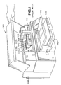
- FIGURE 1 depicts an ink-jet hard copy apparatus, in this exemplary embodiment a computer peripheral printer, 101.
- a housing 103 encloses the electrical and mechanical operating mechanisms of the printer 101. Operation is administrated by an electronic controller (usually a microprocessor-controlled printed circuit board, not shown) connected by appropriate cabling to a computer (not shown).
- Cut-sheet print media 105 loaded by the end-user onto an input tray 107, is fed by a suitable paper-path transport mechanism (not shown) to an internal printing station where graphical images or alphanumeric text is created.
- a carriage 109 mounted on a slider 111, scans the print medium.
- An encoder strip 113 and appurtenant devices are provided for keeping track of the position of the carriage 109 at any given time.
- An ink-jet pen includes a printhead which consists of a number of columns of ink nozzles.
- the columns of nozzles fire ink droplets that are used to create a print column of dots on an adjacently positioned print media as the pen is scanned across the media.
- a given nozzle of the printhead is used to address a given vertical column position, referred to as a picture element, or "pixel," on the print media.
- Horizontal positions on the print media are addressed by repeatedly firing a given nozzle as the pen is scanned.
- a single sweep scan of the pen can print a swath of dots.
- the print media is stepped to permit a series of scans.
- Dot matrix manipulation is used to form alphanumeric characters, graphical images, and even photographic reproductions from the ink drops.
- the pen scanning axis is referred to as the x-axis
- the print media transport axis is referred to as the y-axis
- the ink drop firing direction is referred to as the z-axis .
- the ink when a nozzle is fired, the ink is ejected from the pen at a finite velocity and it must travel a finite distance along the z-axis between the pen and the print media (for convenience and without limitation to the scope of the invention, the word "paper” will be used hereinafter to mean any form of print media). Since the pen is not stopped at each position during scanning in the x-axis, a fired ink droplet will also have a velocity in the x-axis direction as it traverses the distance to the paper surface. Thus, in order to hit a target pixel, any given nozzle should be fired a finite time before the pen positions the nozzle directly over the location where the dot is intended to be printed.
- an average advanced time of the firing signal is calculated by using the expected flight time of the drop and the current pen velocity, each of which is known from the design of a specific implementation of ink-jet hard copy apparatus (e.g., it is known that the maximum allowable carriage speed without print quality degradation is calculated by taking the time it takes for pen control logic circuitry to shift one set of data up to the pen and fire divided by the pen nozzle stagger distance (explained hereinbelow); the flight time is calculated by dividing the nozzle-to-paper spacing by the velocity of the ink drop.
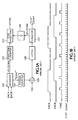
- FIGURE 1A A typical prior art drop firing encoder is shown in FIGURE 1A with a timing diagram therefor shown in FIGURE 1B .
- An encoder 113 provides two output timing signals, "EncA” and "EncB,” which are decoded 121 as fundamental coarse position indicators of where the carriage 209 is during a scan.
- the leading and trailing edge of each encoder signal can thus be used in conjunction with a counter 122 to generate carriage position, tracking carriage movement in units such as 1/150th inch (this value will be used throughout as an exemplary embodiment herein; no limitation on the scope of the invention is intended thereby nor should any be inferred therefrom).
- a series of fire timing pulses, "FTP"_COUNT, is generated for each position signal, allowing the FIRE pulse actually to trigger firing of a plurality of nozzles in the printhead.
- Fire timing pulses are generated continuously by a clock during normal printing and used in accordance with the number of nozzles arrays in a particular printhead design as needed.
- the Fire Position circuitry 123 combines the position information with a value for a nozzle firing register 123 to generate a nozzle firing pulse, "FIRE,” e.g., every period comprising movement of the carriage 1/150th inch.
- the leading or trailing edge is also used in a Period_Counter 124 to determine the carriage velocity.
- the FTP_COUNT pulses provides an extrapolation for the timing of the FTP_COUNT pulses. That is, an extrapolator latch 126_counter 127 takes the measurement of the carriage period as measured in clock cycles divided by the value kept in the extrapolation-division register.
- the FTP_COUNT pulses are also provided 128 as fine position indicator for carriage position.
- the horizontal distance from the actual advanced firing position of a given nozzle to where the drop actually lands is dependent on the scanning velocity of the pen. Knowing the total flight time of the ink drop and the pen scan velocity, the distance can be calculated by multiplying these two values. If the scan velocity of the pen is constant, the amount by which the firing signal precedes each pixel position is a constant. As discussed above, in this case the whole printed image is just shifted by a constant amount; that is, the image is moved by the number of dot positions that equal the over-shoot distance. Compensation in the foregoing manner moves the whole rendered image to attempt to compensate simply for this error. However, this does methodology does nothing to improve instantaneous drop placement accuracy within each scan swath.
- nozzle-to-paper spacing is not a constant.
- the variation in this nozzle-to-paper spacing causes the drop positioning to change non-uniformly across the width of the scan. Therefore, drop positioning will change across the page, causing drops not to hit the intended address pixel grid correctly.
- the firing advance dynamically to remove positioning errors which would result from changes in the nozzle-to-paper spacing during any one scan.
- a further time-of-firing complication is added when a vertical column of nozzles on the printhead is broken into groups, called “primitives,” generally for use with different color inks being fired from a single printhead.
- the nozzles are staggered horizontally in the pen scan x-axis direction by an amount slightly less than the space between print columns divided by the number of nozzles per primitive. This means that the firing from one nozzle to the next occurs at a defined spacing, known as the “stagger distance,” (or simply “stagger”) which is less than the spacing between dots on the media.
- stagger time is calculated taking the time it takes the carriage to traverse the 1/150th inch and dividing this time by the number of stagger distances in that 1/150th inch). In this manner, the nozzles of each primitive can fire sequentially to create a vertical column of dots on the paper.
- the present invention provides an ink drop fire timing control device for an ink-jet hard copy mechanism for producing dot matrix printing on print media, the hard copy mechanism including an ink-jet pen and a carriage for scanning the pen across print media along a linear axis.
- the device includes comprising: a mechanism for generating periodic carriage position signals as the carriage is scanning the pen across print media along a linear axis; a mechanism for producing ink drop fire timing signals based upon the periodic carriage position signals; and a flight compensation mechanism for extrapolating a value representative of expected ink drop flight time error from the pen to the print media and advancing the ink drop fire timing signals to compensate for the expected ink drop flight time error such that ink drop flight time is compensated for velocity changes of the carriage as the carriage traverses the linear axis, wherein scanning position interrupt signals are generated by comparing carriage position with a next predetermined interrupt position.
- the present invention provides an ink drop fire timing control device for an ink-jet hard copy mechanism for producing dot matrix printing on print media, the hard copy mechanism including an ink-jet pen, a carriage for scanning the pen across print media along a linear axis, and mechanism for generating periodic carriage position signals representative of periodic predetermined pen scanning positions along the axis as the carriage is scanning the pen across print media along a linear axis.
- the timing control device includes: paper shape compensation mechanism for generating a value representative of expected flight time for each of the periodic predetermined pen scanning positions along the axis calculated from a predetermined paper shape profile; and a mechanism for adjusting ink drop fire timing based on the value representative of expected flight time such that ink drops are ejected from the pen before the carriage positions the pen at a position for firing based on the signals representative of periodic predetermined pen scanning positions along the axis.
- the present invention provides an ink drop fire timing control method for an ink-jet hard copy mechanism for producing dot matrix printing on target pixels of a print media
- the hard copy mechanism including an ink-jet pen having a printhead with a plurality of ink drop firing nozzles arrayed as a staggered vertical column, a carriage for scanning the pen across print media along a linear horizontal axis, and mechanism for generating periodic carriage position signals representative of periodic predetermined pen scanning positions along the axis as the carriage is scanning the pen across print media along a linear axis.
- the method includes the steps of:
- the step of providing a signal indicative of expected flight time of a drop from the printhead to the print media includes the steps of:
- the present invention provides an ink-jet paper shape compensation device for generating a value representative of expected flight time for each of the periodic predetermined pen scanning positions along the axis.
- the paper shape compensation device includes: a re-loadable down counter mechanism for counting at each of the periodic predetermined pen scanning positions along the axis; and connected to the counter mechanism, mechanism for changing the value representative of expected flight time such that the value representative of expected flight time is incremented when pen-to-paper spacing is increasing and decremented when pen-to-paper spacing is decreasing at each of the periodic predetermined pen scanning positions along the axis.
- the present invention uses combinatorial and sequential logic as shown in FIGURE 2, referred to generically hereinafter as the Velocity Compensator 200, to vary the timing of fire pulses to compensate for variation in the x-axis velocity in a nozzle firing timing circuit.
- FIGURE 3 An accompanying timing waveform diagram is provided in FIGURE 3 in which:
- the encoder strip 113 is used to generate a series of pulses, EncA and EncB, as the carriage 109 translates back-and-forth along the x-axis.
- the encoder signal will be used to generate nozzle firing signals that occur when the carriage 109 has reached a desired position.
- use of a FLIGHT_TIME_REGISTER 203 compensation enables the production of firing signals at a programmable time before the carriage 109 reaches the target position to compensate for the time that it takes a fired ink drop to reach the print medium and the x-axis velocity imparted to a fired ink drop by the carriage 109.
- An apt analogy would be the dropping of a free-fall bomb prior to the airplane actually being directly over the target.
- EFT EXPECTED_FLIGHT_TIME
- a piecewise linear approximation to actual paper shape is generated as schematically depicted in FIGURE 6, where the view is looking into the printer along the y-axis.
- the paper shape compensator 400 is implemented by using the minimum time unit used to describe ink drop flight time.
- a flight time change can be implemented as a simple, programmable incrementer/decrementer.
- the circuitry that determines if the flight time is updated is implemented by using a simple re-loadable, down counter that counts down at each decision interval, viz. the time it takes the carriage to move 1/150th inch in this exemplary embodiment. When the counter counts down to zero, the flight time is either incremented or decremented and the counter is re-loaded with the programmable value.
- the programmable value correlates to the rate at which the pen to paper spacing is changing.
- the flight time is incremented if the spacing is increasing and is decremented if the spacing is decreasing.
- the profile is generated as a piecewise linear approximation of actual contouring of a sheet of media on the printing station platen of the hard copy apparatus.
- ExtPos changes at every FTP_Count. Any number of linear segments can be used.
- Four parameters are maintained in respective registers: Freq_Reg 401, Mult_Reg 402, Slope_Reg 403, and Flight_Time_Reg 203 (preferably, the first three registers 401, 402, 403 are actually coded into a single register to minimize system delay), FIGURE 4.
- the first three registers 401, 402, 403 are first set, the Expected_Flight_Time value for the start of the print zone is set in the Flight_Time_Reg 203.
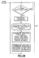
- the decision to perform changes and the actual changes are made as the carriage 209 passes each 1/150-inch position during a scan of the x-axis after the print zone is entered.
- the Freq_Reg 401 determines how often the Flight_Time_Register 203 is updated once the Print-Zone has been entered, step 503.
- a frequency decrementer, Freq_Dec, 405 is loaded with the with content of the Freq_Reg 401, step 505.
- the value is decremented at every 1/150th inch until it reaches zero, triggering the next stage. Note that when the Freq_Dec 405 reaches zero it also causes itself to be reloaded with the value of Freq_Reg 405 again to start timing for the next update, step 509.
- the Mult_Reg 402 stage determines how much to change the flight time parameter in the Flight_Time_Reg 203.
- the value of Mult_Reg 402 is loaded, step 511, into a decrementer, Mult_Dec 407.
- the Mult_Dec 407 counts down to zero and stays there until the next trigger from the Freq_Dec 405, step 513.
- the value of the Flight_Time_Reg 203 is changed by a count of 1, steps 515.
- the plus or minus determination for incrementing or decrementing the Flight_Time_Reg 203 is provided by the value programmed in the Slope_Reg 403.
- the Slope_Reg 403 provides a value based on a measurement taken of the distance between a sensor and the paper.
- the values programmed in the Freq_Reg 401, the Mult_Reg 402, and the Slope_Reg 403 are based on mechanism measurements taken of the distance sensed.
- U.S. Patent Nos. 5,262,797 and 5,289,208 and 5,414,453 and 5,448,269 include exemplary methods and apparatus assigned to the common assignee of the present invention and are incorporated herein by reference. In the present best mode, an actual paper shape profile along the x-axis is generated using test patterns as in the patents cited immediately above.
- This profiling can be accomplished during product testing during manufacture or, in a programmable implementation by providing each hard copy apparatus with a test mode capability whereby the end-user can generate a profile for the particular print media to be used (e.g., plain paper, photographic quality paper, transparencies, and the like) prior to an actual print job.
- print media e.g., plain paper, photographic quality paper, transparencies, and the like
- real time pen-to-paper distance sensing can be used during a scan.
- Such techniques are all known in the art and within the scope of the present invention paper shape compensation method and apparatus. It will be recognized by a person skilled in the art that a further description of such systems here is not essential to an understanding of the method and apparatus of the present invention.
- the number and position of the carriage position Interrupts is determined by the firmware programming employed for a specific implementation. In a properly designed system, these Interrupts will occur wherever there is a change in the linear approximation of paper shape. Thus, the foregoing process loops continuously until the Print-Zone is exited at which time the update process halts and the firmware can initialize the parameters for the next scan along the x-axis, shown generically as steps 517.
- the Flight_Time_Register 203 is potentially updated on any carriage Position (FIG.3) and additionally enables a Carriage_Position_Interrupt such that it can be notified when the Freq_Reg 401, Mult_Reg 402, and Slope_Reg 403 parameters can be updated to approximate the next paper shape segment.
- the velocity of the pen during scanning is measured by counting clock pulses between encoder edges.
- the desired spacing of the output ink drops is known based on the resolution of the printer, e.g., 300 DPI, 600 DPI, 750 DPI, et seq.
- t EE The measured time between encoder edges, t EE , is divided by this value which give the time between dot positions.
- t drop t EE + DPEE
- this value is used to count out drop positions.
- the present invention leverages the prior art calculations by dividing the flight time, t fly of the drop by the calculated time between drop positions, t drop .
- This value can also be thought of as a velocity compensation value since the effect is to advance the drop firing by the expected flight time.
- fire timing velocity compensation is calculated using the stagger distance.
- the calculated flight time correction value can correct a drop position to within a significant fraction of a dot width. Fractional values of the calculation thus can be discarded with no impact on print quality.
- the Flight_Time_Reg 203 is shown and is, again, receiving an Expected_Flight_Time signal at the start of each period, in this exemplary embodiment each time the carriage 209 has moved 1/150th inch. This input is then used to extrapolate and predetermine a Flight_Time_Error which is equivalent to the number of FTP_COUNT pulses that a fired drop will travel along the scan axis from the time it is fired until it strikes the paper. Hence, it is also the advance time of firing required to compensate for pen-to-paper distance fluctuations as well as the actual carriage velocity.
- the encoder signals, EncA and EncB are input to a decoder 201; a Position Counter 205 keeps track of position in the x-axis and the Edge pulse is again used to with a Period Counter 207, extrapolation divider, "EXTRA_DIV,” 209, latch 211, counter 213, and register 215 to derive the actual carriage velocity and an Extrapolated_ Position pulse stream, "ExtPos.”
- the speed of the carriage is thus determined by measuring the number of clock cycles between each encoder edge; four separate counters are used with one each assigned to one encoder edge (EncA rise, EncA fall, EncB rise, EncB fall).
- EncA and EncB "EDGE" sequence also indicates whether the current printing is occurring left-to-right or right-to-left.
- ExtPos is simply used directly as the current position to determine when a stagged group of nozzles starts to fire in accordance with the FTP pulses. In accordance with the present invention, it is further extrapolated and corrected by the Flight_Time_Error to provide advanced firing. In other words, in the prior art the carriage motion produces firing signals that occur when the carriage has reached an indicated position.
- the Flight_Time_Error value is the number of printhead nozzle address times that the ink drop will travel along the x-axis from the actual moment of firing to the time it strikes the adjacent print medium.
- the Flight_Time_Error is also thus a velocity compensation value as encoder edge pulses are substantially instantaneously extrapolated during each scan sweep regardless of velocity fluctuations and carriage acceleration/deceleration zones at each side of the print zone.
- the Expected_Flight_Time input written to the Flight_Time_Register 203 can be an average drop flight time as measure in system clocks rather than as calculated in accordance with the circuit and method disclosed in FIGURES 4 - 6.
- the paper shape compensation logic can be bypassed in favor of a simpler predetermined, preprogrammed flight time constant.
- the Flight_Time_Error value is added to the fire position register when the carriage is printing in a first direction, e.g., left to right on the first swath scan, and is subtracted to the fire position register when the carriage is printing in a second direction, e.g., right to left scan.
- FIGURES 7 and 8 are exemplary plots showing the effect of the use of Flight_Time_Error compensation.
- FIGURE 7 is for a print speed of 107-ips and FIGURE 8 is for a print speed of 60-ips.
- ColumnSyncK shows where the printhead firing pulse occurs without compensation
- ColumnSyncCMY shows where the printer fire with a determined 50-microsecond compensation based on the programmed value in the Flight_Time_Register 203.
- the system as explained hereinabove compensates for the time that it takes each fired drop to reach the paper, compensating for variations in pen-to-paper distance and carriage velocity changes.
- the estimated current carriage position is accurate to one pen address time, or stagger.
- the ink drop thus hits the intended target pixel without any substantial offset.
Applications Claiming Priority (2)
| Application Number | Priority Date | Filing Date | Title |
|---|---|---|---|
| US162369 | 1998-09-28 | ||
| US09/162,369 US6361137B1 (en) | 1998-09-28 | 1998-09-28 | Method and apparatus for compensating for variations in printhead-to-media spacing and printhead scanning velocity in an ink-jet hard copy apparatus |
Publications (2)
| Publication Number | Publication Date |
|---|---|
| EP0990531A1 true EP0990531A1 (de) | 2000-04-05 |
| EP0990531B1 EP0990531B1 (de) | 2005-12-14 |
Family
ID=22585334
Family Applications (1)
| Application Number | Title | Priority Date | Filing Date |
|---|---|---|---|
| EP99117655A Expired - Lifetime EP0990531B1 (de) | 1998-09-28 | 1999-09-07 | Tintenstrahldrucker mit einer Einrichtung zur Kompensation der Flugzeitsvariation der Tintentröpfen |
Country Status (4)
| Country | Link |
|---|---|
| US (1) | US6361137B1 (de) |
| EP (1) | EP0990531B1 (de) |
| KR (1) | KR100636480B1 (de) |
| DE (1) | DE69928882T2 (de) |
Cited By (3)
| Publication number | Priority date | Publication date | Assignee | Title |
|---|---|---|---|---|
| EP1287992A3 (de) * | 2001-08-27 | 2003-09-03 | Canon Kabushiki Kaisha | Tintenstrahldruckvorrichtung und Tintenstrahldruckverfahren |
| EP1449663A1 (de) * | 2002-03-14 | 2004-08-25 | Seiko Epson Corporation | Drucker, druckverfahren, programm, speichermedium und rechnersystem |
| GB2491868A (en) * | 2011-06-15 | 2012-12-19 | Inca Digital Printers Ltd | Print gap compensation |
Families Citing this family (15)
| Publication number | Priority date | Publication date | Assignee | Title |
|---|---|---|---|---|
| US7025433B2 (en) * | 2002-11-27 | 2006-04-11 | Hewlett-Packard Development Company, L.P. | Changing drop-ejection velocity in an ink-jet pen |
| US6877832B2 (en) * | 2003-03-11 | 2005-04-12 | Hewlett-Packard Development Company, L.P. | Instruction architecture using two instruction stacks |
| US20040233244A1 (en) * | 2003-05-21 | 2004-11-25 | Elgee Steven B. | Printhead collision detection |
| US20060268056A1 (en) * | 2005-05-27 | 2006-11-30 | Josep-Lluis Molinet | Non-staggered inkjet printhead with true multiple resolution support |
| TWI288709B (en) * | 2006-07-19 | 2007-10-21 | Sunplus Technology Co Ltd | Method and system for automatically calibrating speed of carriage for an inkjet print head |
| CN100577431C (zh) * | 2006-09-05 | 2010-01-06 | 凌阳科技股份有限公司 | 可自动校正喷墨头承座速度不均匀的方法及系统 |
| JP2010005859A (ja) * | 2008-06-25 | 2010-01-14 | Seiko Epson Corp | 流体噴射装置及び流体噴射方法 |
| US8197022B2 (en) * | 2009-09-29 | 2012-06-12 | Eastman Kodak Company | Automated time of flight speed compensation |
| DE102010017004B4 (de) * | 2010-05-18 | 2017-11-02 | Océ Printing Systems GmbH & Co. KG | Bearbeitungseinrichtung und Verfahren zum Ansteuern einer Bearbeitungseinrichtung |
| JP5868037B2 (ja) * | 2011-06-28 | 2016-02-24 | キヤノン株式会社 | インクジェット記録装置およびインクジェット記録方法 |
| US8991960B2 (en) | 2012-08-24 | 2015-03-31 | Hewlett-Packard Development Company, L.P. | Compensation of bi-directional alignment error |
| US9102142B2 (en) | 2013-01-30 | 2015-08-11 | Hewlett-Packard Development Company, L.P. | Method of controlling inkjet printing |
| JP5799972B2 (ja) * | 2013-03-27 | 2015-10-28 | ブラザー工業株式会社 | インクジェット記録装置及びズレ量設定方法 |
| JP5799971B2 (ja) * | 2013-03-27 | 2015-10-28 | ブラザー工業株式会社 | インクジェット記録装置 |
| CN107206819B (zh) | 2015-02-18 | 2019-03-22 | 惠普发展公司,有限责任合伙企业 | 笔到纸间隔的估计 |
Citations (3)
| Publication number | Priority date | Publication date | Assignee | Title |
|---|---|---|---|---|
| EP0040313A2 (de) * | 1980-05-20 | 1981-11-25 | Monarch Marking Systems, Inc. | Matrix-Drucker |
| US4524364A (en) * | 1982-11-22 | 1985-06-18 | Xerox Corporation | Circuitry for correcting dot placement for oscillating carriage ink jet printer |
| EP0622220A2 (de) * | 1993-04-30 | 1994-11-02 | Hewlett-Packard Company | Richtvorrichtung für Vielfach-Tintenstrahl-Kassetten beim Zweirichtungsdruck durch Abtasten eines Testmusters |
Family Cites Families (8)
| Publication number | Priority date | Publication date | Assignee | Title |
|---|---|---|---|---|
| US4786803A (en) | 1987-06-01 | 1988-11-22 | Hewlett-Packard Company | Single channel encoder with specific scale support structure |
| US4789874A (en) | 1987-07-23 | 1988-12-06 | Hewlett-Packard Company | Single channel encoder system |
| US5262797A (en) | 1990-04-04 | 1993-11-16 | Hewlett-Packard Company | Monitoring and controlling quality of pen markings on plotting media |
| US5170047A (en) * | 1991-09-20 | 1992-12-08 | Hewlett-Packard Company | Optical sensor for plotter pen verification |
| US5289208A (en) | 1991-10-31 | 1994-02-22 | Hewlett-Packard Company | Automatic print cartridge alignment sensor system |
| US5988784A (en) * | 1992-11-12 | 1999-11-23 | Canon Kabushiki Kaisha | Method and apparatus for recording information with corrected drive timing |
| US5414453A (en) | 1993-04-30 | 1995-05-09 | Hewlett-Packard Company | Use of a densitometer for adaptive control of printhead-to-media distance in ink jet printers |
| JP3521569B2 (ja) * | 1995-09-05 | 2004-04-19 | ブラザー工業株式会社 | 印字制御装置 |
-
1998
- 1998-09-28 US US09/162,369 patent/US6361137B1/en not_active Expired - Fee Related
-
1999
- 1999-09-07 EP EP99117655A patent/EP0990531B1/de not_active Expired - Lifetime
- 1999-09-07 DE DE69928882T patent/DE69928882T2/de not_active Expired - Lifetime
- 1999-09-22 KR KR1019990040913A patent/KR100636480B1/ko not_active IP Right Cessation
Patent Citations (3)
| Publication number | Priority date | Publication date | Assignee | Title |
|---|---|---|---|---|
| EP0040313A2 (de) * | 1980-05-20 | 1981-11-25 | Monarch Marking Systems, Inc. | Matrix-Drucker |
| US4524364A (en) * | 1982-11-22 | 1985-06-18 | Xerox Corporation | Circuitry for correcting dot placement for oscillating carriage ink jet printer |
| EP0622220A2 (de) * | 1993-04-30 | 1994-11-02 | Hewlett-Packard Company | Richtvorrichtung für Vielfach-Tintenstrahl-Kassetten beim Zweirichtungsdruck durch Abtasten eines Testmusters |
Cited By (5)
| Publication number | Priority date | Publication date | Assignee | Title |
|---|---|---|---|---|
| EP1287992A3 (de) * | 2001-08-27 | 2003-09-03 | Canon Kabushiki Kaisha | Tintenstrahldruckvorrichtung und Tintenstrahldruckverfahren |
| US6910752B2 (en) | 2001-08-27 | 2005-06-28 | Canon Kabushiki Kaisha | Ink jet printing apparatus and method for adjusting driving timing of ink ejection |
| EP1449663A1 (de) * | 2002-03-14 | 2004-08-25 | Seiko Epson Corporation | Drucker, druckverfahren, programm, speichermedium und rechnersystem |
| EP1449663A4 (de) * | 2002-03-14 | 2007-08-15 | Seiko Epson Corp | Drucker, druckverfahren, programm, speichermedium und rechnersystem |
| GB2491868A (en) * | 2011-06-15 | 2012-12-19 | Inca Digital Printers Ltd | Print gap compensation |
Also Published As
| Publication number | Publication date |
|---|---|
| KR20000023382A (ko) | 2000-04-25 |
| DE69928882T2 (de) | 2006-08-24 |
| US6361137B1 (en) | 2002-03-26 |
| EP0990531B1 (de) | 2005-12-14 |
| KR100636480B1 (ko) | 2006-10-18 |
| DE69928882D1 (de) | 2006-01-19 |
Similar Documents
| Publication | Publication Date | Title |
|---|---|---|
| EP0990531B1 (de) | Tintenstrahldrucker mit einer Einrichtung zur Kompensation der Flugzeitsvariation der Tintentröpfen | |
| US6315383B1 (en) | Method and apparatus for ink-jet drop trajectory and alignment error detection and correction | |
| US6457806B2 (en) | Ink-jet print pass microstepping | |
| US6331038B1 (en) | Techniques for robust dot placement error measurement and correction | |
| US6663206B2 (en) | Systems and method for masking stitch errors | |
| EP1819516B1 (de) | Drucken eines striches in einem strichcode | |
| JP2000238259A (ja) | インクジェットプリンタにおける液滴配置エラーの補正方法 | |
| EP0761453A1 (de) | Verfahren zum Betreiben eines Tintenstrahldruckers und Tintenstrahldrucker, dieses Verfahren benutzend | |
| US7237858B2 (en) | Printing apparatus, printing method, storage medium, and computer system | |
| US6733101B2 (en) | Printing apparatus and control method therefor | |
| GB2380161A (en) | Determining a print media line-feed advance offset/error compensation from pen swath densities detected from a printed image | |
| US6302506B1 (en) | Apparatus and method for correcting carriage velocity induced ink drop positional errors | |
| US5803628A (en) | Printing apparatus including encoder pending | |
| EP3215368B1 (de) | Duplexdrucken | |
| KR960003351B1 (ko) | 위치검출장치 | |
| EP1057647B1 (de) | Tintenstrahldrucker | |
| US7108344B2 (en) | Printmode for narrow margin printing | |
| US5937145A (en) | Method and apparatus for improving ink-jet print quality using a jittered print mode | |
| JP2010030161A (ja) | 画像形成装置 | |
| US7387357B2 (en) | Calibration method for printing apparatus | |
| US6322184B1 (en) | Method and apparatus for improved swath-to-swath alignment in an inkjet print engine device | |
| JP4976117B2 (ja) | 印刷装置 | |
| JP5101416B2 (ja) | 画像形成装置 | |
| JP2003225999A (ja) | 画像記録装置およびその制御方法 | |
| WO2022203691A1 (en) | Printer alignment calibration |
Legal Events
| Date | Code | Title | Description |
|---|---|---|---|
| PUAI | Public reference made under article 153(3) epc to a published international application that has entered the european phase |
Free format text: ORIGINAL CODE: 0009012 |
|
| AK | Designated contracting states |
Kind code of ref document: A1 Designated state(s): DE GB IT |
|
| AX | Request for extension of the european patent |
Free format text: AL;LT;LV;MK;RO;SI |
|
| 17P | Request for examination filed |
Effective date: 20000524 |
|
| AKX | Designation fees paid |
Free format text: DE GB IT |
|
| RAP1 | Party data changed (applicant data changed or rights of an application transferred) |
Owner name: HEWLETT-PACKARD COMPANY, A DELAWARE CORPORATION |
|
| 17Q | First examination report despatched |
Effective date: 20040220 |
|
| GRAP | Despatch of communication of intention to grant a patent |
Free format text: ORIGINAL CODE: EPIDOSNIGR1 |
|
| GRAS | Grant fee paid |
Free format text: ORIGINAL CODE: EPIDOSNIGR3 |
|
| GRAA | (expected) grant |
Free format text: ORIGINAL CODE: 0009210 |
|
| AK | Designated contracting states |
Kind code of ref document: B1 Designated state(s): DE GB IT |
|
| REG | Reference to a national code |
Ref country code: GB Ref legal event code: FG4D |
|
| REF | Corresponds to: |
Ref document number: 69928882 Country of ref document: DE Date of ref document: 20060119 Kind code of ref document: P |
|
| PLBE | No opposition filed within time limit |
Free format text: ORIGINAL CODE: 0009261 |
|
| STAA | Information on the status of an ep patent application or granted ep patent |
Free format text: STATUS: NO OPPOSITION FILED WITHIN TIME LIMIT |
|
| 26N | No opposition filed |
Effective date: 20060915 |
|
| PGFP | Annual fee paid to national office [announced via postgrant information from national office to epo] |
Ref country code: GB Payment date: 20070926 Year of fee payment: 9 |
|
| PGFP | Annual fee paid to national office [announced via postgrant information from national office to epo] |
Ref country code: IT Payment date: 20070925 Year of fee payment: 9 |
|
| GBPC | Gb: european patent ceased through non-payment of renewal fee |
Effective date: 20080907 |
|
| PG25 | Lapsed in a contracting state [announced via postgrant information from national office to epo] |
Ref country code: IT Free format text: LAPSE BECAUSE OF NON-PAYMENT OF DUE FEES Effective date: 20080907 |
|
| PG25 | Lapsed in a contracting state [announced via postgrant information from national office to epo] |
Ref country code: GB Free format text: LAPSE BECAUSE OF NON-PAYMENT OF DUE FEES Effective date: 20080907 |
|
| REG | Reference to a national code |
Ref country code: DE Ref legal event code: R082 Ref document number: 69928882 Country of ref document: DE Representative=s name: BOEHMERT & BOEHMERT, DE |
|
| REG | Reference to a national code |
Ref country code: DE Ref legal event code: R082 Ref document number: 69928882 Country of ref document: DE Representative=s name: BOEHMERT & BOEHMERT ANWALTSPARTNERSCHAFT MBB -, DE Effective date: 20120611 Ref country code: DE Ref legal event code: R081 Ref document number: 69928882 Country of ref document: DE Owner name: HEWLETT-PACKARD DEVELOPMENT COMPANY, L.P., HOU, US Free format text: FORMER OWNER: HEWLETT-PACKARD CO. (N.D.GES.D.STAATES DELAWARE), PALO ALTO, CALIF., US Effective date: 20120611 |
|
| PGFP | Annual fee paid to national office [announced via postgrant information from national office to epo] |
Ref country code: DE Payment date: 20130820 Year of fee payment: 15 |
|
| REG | Reference to a national code |
Ref country code: DE Ref legal event code: R119 Ref document number: 69928882 Country of ref document: DE |
|
| REG | Reference to a national code |
Ref country code: DE Ref legal event code: R119 Ref document number: 69928882 Country of ref document: DE Effective date: 20150401 |
|
| PG25 | Lapsed in a contracting state [announced via postgrant information from national office to epo] |
Ref country code: DE Free format text: LAPSE BECAUSE OF NON-PAYMENT OF DUE FEES Effective date: 20150401 |