EP0990470A1 - Rolle für einen Aufheizofen zur allgemeinen oder örtlichen Durchlauferwärmung metallischer Produkte mittels Hochleistungsinduktions-Heizeinrichtung - Google Patents
Rolle für einen Aufheizofen zur allgemeinen oder örtlichen Durchlauferwärmung metallischer Produkte mittels Hochleistungsinduktions-Heizeinrichtung Download PDFInfo
- Publication number
- EP0990470A1 EP0990470A1 EP99402367A EP99402367A EP0990470A1 EP 0990470 A1 EP0990470 A1 EP 0990470A1 EP 99402367 A EP99402367 A EP 99402367A EP 99402367 A EP99402367 A EP 99402367A EP 0990470 A1 EP0990470 A1 EP 0990470A1
- Authority
- EP
- European Patent Office
- Prior art keywords
- discs
- roller
- establishment
- currents
- lining
- Prior art date
- Legal status (The legal status is an assumption and is not a legal conclusion. Google has not performed a legal analysis and makes no representation as to the accuracy of the status listed.)
- Withdrawn
Links
- 238000010438 heat treatment Methods 0.000 title claims abstract description 19
- 230000006698 induction Effects 0.000 title claims abstract description 17
- 239000012530 fluid Substances 0.000 claims abstract description 14
- 238000001816 cooling Methods 0.000 claims abstract description 7
- 239000000463 material Substances 0.000 claims abstract description 6
- 229910000831 Steel Inorganic materials 0.000 claims description 17
- 239000010959 steel Substances 0.000 claims description 17
- 238000009434 installation Methods 0.000 claims description 7
- 239000002826 coolant Substances 0.000 claims description 6
- 239000011248 coating agent Substances 0.000 claims description 5
- 238000000576 coating method Methods 0.000 claims description 5
- 238000009413 insulation Methods 0.000 claims description 4
- 238000004381 surface treatment Methods 0.000 claims description 4
- 239000012809 cooling fluid Substances 0.000 claims description 3
- 229910052500 inorganic mineral Inorganic materials 0.000 claims description 3
- 239000011707 mineral Substances 0.000 claims description 3
- 238000005524 ceramic coating Methods 0.000 claims description 2
- 238000006073 displacement reaction Methods 0.000 claims description 2
- 239000003365 glass fiber Substances 0.000 claims description 2
- 239000003999 initiator Substances 0.000 claims description 2
- 230000005855 radiation Effects 0.000 claims description 2
- 230000000712 assembly Effects 0.000 claims 1
- 238000000429 assembly Methods 0.000 claims 1
- 239000002184 metal Substances 0.000 claims 1
- 210000000056 organ Anatomy 0.000 claims 1
- 230000000977 initiatory effect Effects 0.000 abstract 1
- 230000003134 recirculating effect Effects 0.000 abstract 1
- 239000000047 product Substances 0.000 description 31
- 238000005096 rolling process Methods 0.000 description 10
- 239000004020 conductor Substances 0.000 description 4
- 238000003303 reheating Methods 0.000 description 3
- 238000011144 upstream manufacturing Methods 0.000 description 3
- 230000004075 alteration Effects 0.000 description 2
- 239000011810 insulating material Substances 0.000 description 2
- 238000010792 warming Methods 0.000 description 2
- XLYOFNOQVPJJNP-UHFFFAOYSA-N water Substances O XLYOFNOQVPJJNP-UHFFFAOYSA-N 0.000 description 2
- RYGMFSIKBFXOCR-UHFFFAOYSA-N Copper Chemical compound [Cu] RYGMFSIKBFXOCR-UHFFFAOYSA-N 0.000 description 1
- 230000002411 adverse Effects 0.000 description 1
- 238000009749 continuous casting Methods 0.000 description 1
- 229910052802 copper Inorganic materials 0.000 description 1
- 239000010949 copper Substances 0.000 description 1
- 238000010891 electric arc Methods 0.000 description 1
- 239000000839 emulsion Substances 0.000 description 1
- 238000009432 framing Methods 0.000 description 1
- 239000000446 fuel Substances 0.000 description 1
- 238000005098 hot rolling Methods 0.000 description 1
- 230000003100 immobilizing effect Effects 0.000 description 1
- 238000003475 lamination Methods 0.000 description 1
- 230000000670 limiting effect Effects 0.000 description 1
- 239000007769 metal material Substances 0.000 description 1
- 230000036961 partial effect Effects 0.000 description 1
- 230000002093 peripheral effect Effects 0.000 description 1
- 230000002829 reductive effect Effects 0.000 description 1
- 230000000284 resting effect Effects 0.000 description 1
- 239000011265 semifinished product Substances 0.000 description 1
- 229910001220 stainless steel Inorganic materials 0.000 description 1
- 239000010935 stainless steel Substances 0.000 description 1
- 230000008646 thermal stress Effects 0.000 description 1
Images


Classifications
-
- B—PERFORMING OPERATIONS; TRANSPORTING
- B21—MECHANICAL METAL-WORKING WITHOUT ESSENTIALLY REMOVING MATERIAL; PUNCHING METAL
- B21B—ROLLING OF METAL
- B21B39/00—Arrangements for moving, supporting, or positioning work, or controlling its movement, combined with or arranged in, or specially adapted for use in connection with, metal-rolling mills
- B21B39/008—Rollers for roller conveyors
-
- B—PERFORMING OPERATIONS; TRANSPORTING
- B22—CASTING; POWDER METALLURGY
- B22D—CASTING OF METALS; CASTING OF OTHER SUBSTANCES BY THE SAME PROCESSES OR DEVICES
- B22D11/00—Continuous casting of metals, i.e. casting in indefinite lengths
- B22D11/12—Accessories for subsequent treating or working cast stock in situ
- B22D11/128—Accessories for subsequent treating or working cast stock in situ for removing
- B22D11/1287—Rolls; Lubricating, cooling or heating rolls while in use
-
- C—CHEMISTRY; METALLURGY
- C21—METALLURGY OF IRON
- C21D—MODIFYING THE PHYSICAL STRUCTURE OF FERROUS METALS; GENERAL DEVICES FOR HEAT TREATMENT OF FERROUS OR NON-FERROUS METALS OR ALLOYS; MAKING METAL MALLEABLE, e.g. BY DECARBURISATION OR TEMPERING
- C21D9/00—Heat treatment, e.g. annealing, hardening, quenching or tempering, adapted for particular articles; Furnaces therefor
- C21D9/0006—Details, accessories not peculiar to any of the following furnaces
- C21D9/0012—Rolls; Roll arrangements
-
- F—MECHANICAL ENGINEERING; LIGHTING; HEATING; WEAPONS; BLASTING
- F27—FURNACES; KILNS; OVENS; RETORTS
- F27D—DETAILS OR ACCESSORIES OF FURNACES, KILNS, OVENS, OR RETORTS, IN SO FAR AS THEY ARE OF KINDS OCCURRING IN MORE THAN ONE KIND OF FURNACE
- F27D3/00—Charging; Discharging; Manipulation of charge
- F27D3/02—Skids or tracks for heavy objects
- F27D3/026—Skids or tracks for heavy objects transport or conveyor rolls for furnaces; roller rails
-
- F—MECHANICAL ENGINEERING; LIGHTING; HEATING; WEAPONS; BLASTING
- F27—FURNACES; KILNS; OVENS; RETORTS
- F27D—DETAILS OR ACCESSORIES OF FURNACES, KILNS, OVENS, OR RETORTS, IN SO FAR AS THEY ARE OF KINDS OCCURRING IN MORE THAN ONE KIND OF FURNACE
- F27D9/00—Cooling of furnaces or of charges therein
-
- B—PERFORMING OPERATIONS; TRANSPORTING
- B21—MECHANICAL METAL-WORKING WITHOUT ESSENTIALLY REMOVING MATERIAL; PUNCHING METAL
- B21B—ROLLING OF METAL
- B21B27/00—Rolls, roll alloys or roll fabrication; Lubricating, cooling or heating rolls while in use
- B21B27/06—Lubricating, cooling or heating rolls
- B21B27/08—Lubricating, cooling or heating rolls internally
- B21B2027/083—Lubricating, cooling or heating rolls internally cooling internally
-
- C—CHEMISTRY; METALLURGY
- C21—METALLURGY OF IRON
- C21D—MODIFYING THE PHYSICAL STRUCTURE OF FERROUS METALS; GENERAL DEVICES FOR HEAT TREATMENT OF FERROUS OR NON-FERROUS METALS OR ALLOYS; MAKING METAL MALLEABLE, e.g. BY DECARBURISATION OR TEMPERING
- C21D1/00—General methods or devices for heat treatment, e.g. annealing, hardening, quenching or tempering
- C21D1/34—Methods of heating
- C21D1/42—Induction heating
-
- C—CHEMISTRY; METALLURGY
- C21—METALLURGY OF IRON
- C21D—MODIFYING THE PHYSICAL STRUCTURE OF FERROUS METALS; GENERAL DEVICES FOR HEAT TREATMENT OF FERROUS OR NON-FERROUS METALS OR ALLOYS; MAKING METAL MALLEABLE, e.g. BY DECARBURISATION OR TEMPERING
- C21D9/00—Heat treatment, e.g. annealing, hardening, quenching or tempering, adapted for particular articles; Furnaces therefor
- C21D9/0081—Heat treatment, e.g. annealing, hardening, quenching or tempering, adapted for particular articles; Furnaces therefor for slabs; for billets
-
- F—MECHANICAL ENGINEERING; LIGHTING; HEATING; WEAPONS; BLASTING
- F27—FURNACES; KILNS; OVENS; RETORTS
- F27D—DETAILS OR ACCESSORIES OF FURNACES, KILNS, OVENS, OR RETORTS, IN SO FAR AS THEY ARE OF KINDS OCCURRING IN MORE THAN ONE KIND OF FURNACE
- F27D9/00—Cooling of furnaces or of charges therein
- F27D2009/0002—Cooling of furnaces
- F27D2009/001—Cooling of furnaces the cooling medium being a fluid other than a gas
- F27D2009/0013—Cooling of furnaces the cooling medium being a fluid other than a gas the fluid being water
-
- Y—GENERAL TAGGING OF NEW TECHNOLOGICAL DEVELOPMENTS; GENERAL TAGGING OF CROSS-SECTIONAL TECHNOLOGIES SPANNING OVER SEVERAL SECTIONS OF THE IPC; TECHNICAL SUBJECTS COVERED BY FORMER USPC CROSS-REFERENCE ART COLLECTIONS [XRACs] AND DIGESTS
- Y02—TECHNOLOGIES OR APPLICATIONS FOR MITIGATION OR ADAPTATION AGAINST CLIMATE CHANGE
- Y02P—CLIMATE CHANGE MITIGATION TECHNOLOGIES IN THE PRODUCTION OR PROCESSING OF GOODS
- Y02P10/00—Technologies related to metal processing
- Y02P10/25—Process efficiency
Definitions
- the present invention relates to a device intended for an installation for heating the parade of banks of metallurgical products, to undergo later hot deformations. These products are notably blooms, billets or slabs, which must be heated or reheated before being flattened and / or widened by passages if necessary between the rollers of a rolling mill.
- the products semi-finished products such as blooms, slabs, billets
- hot rolling mill trains, type rough-planers and finishers in which these products undergo changes in their dimensions due to rolling, in order to obtain products finished.
- slabs whose dimensions classics reach 10 m long, 250 mm thick and 1.50 m wide are directed, before reaching the first train of roughing rolling mills, to an oven heating, especially gas or fuel, in which the temperature of these products is brought to around 1200 ° C.
- these heated products are routed, in particular at an average speed of 1 m / s, from continuously thanks to roller tracks whose lengths can reach several tens of meters, towards the rolling mill stands.
- the slabs heated to 1200 ° C undergo a internal room temperature cooling which is especially sensitive to the edges of these, the edges being the lateral edges in the direction longitudinal of steel products and in particular of slabs.
- upstream of the rolling mill stands and particularly upstream of a so-called rolling mill train pavers, to compensate for the lowering of the level of the banks, which can reach, depending continuously moving product speeds steel and the distance between the furnace of reheating and entering the rolling mill train, a hundred degrees Celsius.
- this calorific intake can be obtained by an induction heater located upstream of the rolling mill train.
- Induction heaters like those described in French Patent No. 2,692,828 belonging to to the Applicant Company, are of the high power type with regard to induction heating devices prior to this solution.
- the power to inject can conventionally reach 400 to 800 kW per inductor.
- the seat of the circulation currents induced by the field variable magnetic is located in a loop in the thickness of the part; induced current density is very important on the banks, which causes the desired heating.
- the present invention therefore aims to overcome these disadvantages by proposing a device which avoids the appearance of extra-breaking electric arcs between the steel product and the rollers supporting said product, in the reheating zone of the induction heating, to improve the quality and the surface finish of the finished product.
- the device intended for an installation for heating the parade of product edges metallurgical, by heating devices by high power induction, comprising at least one support roll of the steel product, this being positioned in the vicinity of the heating devices by induction, is characterized in that the roller has a metallic central core, possibly provided with a plurality of holes for the establishment of lost or recirculated fluid cooling systems between the axis of the roller and its periphery, this core central being coated on its external surface with means avoiding the establishment of traffic currents initiators of extra-breaking electric arcs between the steel product and the surface of the roller.
- the device for support to be installed in the action area an induction heater, and particularly on both sides of the inductor generating the variable magnetic field, has a roller 1.
- This roller 1 which must be in contact with the product steel working in the procession, includes means 3 to electrically isolate the central part of the roll 1 in relation to the resting steel product on its periphery.
- the means 3 making it possible to isolate or to prevent the establishment of current flow are made from a first shaft 4 formed by a tube, in particular of circular cross section, in which can circulate a coolant (water, oil etc ).
- This shaft 4 is provided with a plurality of 5 radial holes evenly distributed along the length of said tube 4 which open into an annular space 6 formed between this first tube 4 and a second tube 7 concentric with the previous one and which also includes a plurality of second radial orifices 8 in communication with the previous ones.
- a third tube 9 concentric with tubes 4 and 7, which has a plurality of third 10 orifices communicating with a annular space 11 formed by the external wall 12 of the second tube 7 and the inner wall 13 of the third tube 9.
- the roll 1 object of the invention comprises two distinct networks which allow to establish a recycled circulation of fluid.
- This fluid is preferably a cooling such as in particular water, oil, or an emulsion.
- coolant emerging directly on the periphery of the external surface 14 of the third tube 9 is taken up by the pipes of the second network and redirected to the annular space 6 formed around the first tube 4 so as to be there recycled or recirculated to the first supply network.
- the tubes 4 and 7 are combined and do not form a single hollow shaft, also having a plurality of 16 radial holes which open out thanks to orifices 17 made in a third tube 9 concentric with the previous tree, so as not to realize only one supply network says lost fluid.
- These linings 18 made of an insulating material with regard to electrical conductivity, especially based of glass fibers, enclose the external wall 14 of the tube 9 at the orifices 10 and 17 of fluid outlet from cooling.
- fittings 18 avoid or limit the establishment of circulation currents within the tree, they are shaped into rings and fit on the outer wall 14 of tube 9. Their lateral displacement is limited by in part by shoulders 19 made on the wall external 14 of tube 9 receiving them, and immobilizing them in rotation is obtained through a key 20 or a similar member engaged at the same time in grooves 21 formed in the tube 9 and in the lining 18 of insulation.
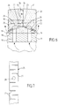
- the inclined walls 24 of these linings 18 are coated with a drain 25 preferably made in a material with high conductivity, so as to form a thermal bridge between the linings 18 and discs 26 in contact with this drain 25.
- FIG. 7 is a view partial developed of the drain 25.
- this drain is formed of a copper strip which is provided laterally of a plurality of grooves 27 in order to ability to adjust to beveled walls 24 formed on the insulating fittings 18.
- This drain 25 comprises also holes 28 for the passage of the fluid of cooling.
- a plurality is produced discs 26 whose internal bore 29 has a tapered so as to fit on the sides bevelled 24 insulating rings 18 and drain 25.
- These discs 26 whose thickness will be calculated so optimal with regard to thermal stresses and mechanical, cooperate in their bore 29 to conical bearing with the drain 25 and are secured thanks to a mounting opposite 30 of two discs, the conical walls meet at their top, so more the discs are closer to each other, the more entrapment is effective.
- the discs 26 are provided with a means of tightening 30.
- the wall external 31 of the discs 26 intended to be in contact with the steel product has a convex profile whose top of the rope leads to the right of the junction 32 of two discs.
- this profile we limit the extent of contact surfaces between the steel product and the discs at a plurality of points, which prevents the establishment of surface traffic currents some discs. Indeed, if the contact of the product by relative to the peripheral surface of a disc takes place not punctually, but according to a generator, this generator can cut a current line from circulation and therefore create an extra-breaking electric arc.
- the discs Due to the design of the mounting system discs relative to the tubes, the discs are insulated electrically relative to each other and there are little risk of arcing.
- the junction zone 32 between the two discs defines a space forming a channel for the evacuation of the coolant, being understood that the fluid only escapes through this channel 33 when using a lost fluid roller.
- the end of the channel 33 located substantially perpendicular to the convex profile practiced on the discs 26, has a diameter restriction formed by two small shoulders 34 reported on each of flanks of the discs.
- This diameter restriction makes it possible to generate a device for cutting off radiation from of the product in circulation which is at a temperature close to 1200 ° C.
- a roll 1 it comprises a core made in a metallic material, similar to the central part of the roller according to the first embodiment (fluid lost or recirculated fluid), this central part being coated, thanks to a surface treatment, with a layer of insulating material with regard to the passage of the currents of circulation.
- this surface treatment can be in particular a ceramic coating.
- this surface treatment can be a mineral coating, or any other type of coating, electrically insulating, and having mechanical resistance and resistance properties temperature, required in this type of application.
- the invention as described above offers multiple advantages because it allows the use of reheating installations using devices by very high power induction, which have higher yields compared to traditional gas or oil heating, but which have the downside, given the current densities induced induced to generate electric arcs extra-rupture which should be reduced or even delete in order to obtain a finished product with optimal surface condition.
- This type of roller is particularly intended for an installation for the global or localized heating at the parade of products metallurgical, by heating devices by high power induction.
Landscapes
- Engineering & Computer Science (AREA)
- Mechanical Engineering (AREA)
- Chemical & Material Sciences (AREA)
- General Engineering & Computer Science (AREA)
- Thermal Sciences (AREA)
- Crystallography & Structural Chemistry (AREA)
- Materials Engineering (AREA)
- Metallurgy (AREA)
- Organic Chemistry (AREA)
- Physics & Mathematics (AREA)
- General Induction Heating (AREA)
- Rolls And Other Rotary Bodies (AREA)
- Furnace Details (AREA)
Applications Claiming Priority (2)
| Application Number | Priority Date | Filing Date | Title |
|---|---|---|---|
| FR9812252A FR2783727A1 (fr) | 1998-09-30 | 1998-09-30 | Rouleau destine a une installation pour le chauffage au defile de rives de produits metallurgiques, par des dispositifs de chauffage par induction de forte puissance |
| FR9812252 | 1998-09-30 |
Publications (1)
| Publication Number | Publication Date |
|---|---|
| EP0990470A1 true EP0990470A1 (de) | 2000-04-05 |
Family
ID=9531045
Family Applications (1)
| Application Number | Title | Priority Date | Filing Date |
|---|---|---|---|
| EP99402367A Withdrawn EP0990470A1 (de) | 1998-09-30 | 1999-09-28 | Rolle für einen Aufheizofen zur allgemeinen oder örtlichen Durchlauferwärmung metallischer Produkte mittels Hochleistungsinduktions-Heizeinrichtung |
Country Status (3)
| Country | Link |
|---|---|
| EP (1) | EP0990470A1 (de) |
| JP (1) | JP2000220970A (de) |
| FR (1) | FR2783727A1 (de) |
Cited By (1)
| Publication number | Priority date | Publication date | Assignee | Title |
|---|---|---|---|---|
| WO2002103066A1 (de) * | 2001-06-15 | 2002-12-27 | Sms Demag Aktiengesellschaft | Rollgangsrolle, insbesondere für den transport von ofenwarmem, metallischem bandmaterial |
Citations (4)
| Publication number | Priority date | Publication date | Assignee | Title |
|---|---|---|---|---|
| JPS59158984A (ja) * | 1983-03-02 | 1984-09-08 | 三菱電機株式会社 | 誘導加熱装置用押し棒 |
| FR2580523A1 (fr) * | 1984-12-17 | 1986-10-24 | Jakoubovitch A | Dispositif de chauffage de rives d'ebauche par induction |
| JPH01299702A (ja) * | 1988-05-25 | 1989-12-04 | Hitachi Ltd | 温間圧延方法、及びその装置 |
| DE29600297U1 (de) * | 1996-01-10 | 1996-02-29 | Cascadura Ind Gmbh | Elektrisch isolierende Walze |
-
1998
- 1998-09-30 FR FR9812252A patent/FR2783727A1/fr active Pending
-
1999
- 1999-09-28 EP EP99402367A patent/EP0990470A1/de not_active Withdrawn
- 1999-09-30 JP JP11277909A patent/JP2000220970A/ja active Pending
Patent Citations (4)
| Publication number | Priority date | Publication date | Assignee | Title |
|---|---|---|---|---|
| JPS59158984A (ja) * | 1983-03-02 | 1984-09-08 | 三菱電機株式会社 | 誘導加熱装置用押し棒 |
| FR2580523A1 (fr) * | 1984-12-17 | 1986-10-24 | Jakoubovitch A | Dispositif de chauffage de rives d'ebauche par induction |
| JPH01299702A (ja) * | 1988-05-25 | 1989-12-04 | Hitachi Ltd | 温間圧延方法、及びその装置 |
| DE29600297U1 (de) * | 1996-01-10 | 1996-02-29 | Cascadura Ind Gmbh | Elektrisch isolierende Walze |
Non-Patent Citations (2)
| Title |
|---|
| DATABASE WPI Section Ch Week 8442, Derwent World Patents Index; Class M24, AN 84-260343, XP002104647 * |
| PATENT ABSTRACTS OF JAPAN vol. 014, no. 087 (M - 0937) 19 February 1990 (1990-02-19) * |
Cited By (2)
| Publication number | Priority date | Publication date | Assignee | Title |
|---|---|---|---|---|
| WO2002103066A1 (de) * | 2001-06-15 | 2002-12-27 | Sms Demag Aktiengesellschaft | Rollgangsrolle, insbesondere für den transport von ofenwarmem, metallischem bandmaterial |
| CN100449007C (zh) * | 2001-06-15 | 2009-01-07 | Sms迪马格股份公司 | 用于输送炉内加热的金属带的辊道辊 |
Also Published As
| Publication number | Publication date |
|---|---|
| JP2000220970A (ja) | 2000-08-08 |
| FR2783727A1 (fr) | 2000-03-31 |
Similar Documents
| Publication | Publication Date | Title |
|---|---|---|
| EP0182716B1 (de) | Anstreifring für eine Gasturbine | |
| RU2286396C2 (ru) | Ролик рольганга для транспортировки нагретого в печи металлического листового материала | |
| FR2752134A1 (fr) | Dispositif de chauffage par induction et installation de traitement thermique en continu comportant un tel dispositif | |
| FR2644088A1 (fr) | Procede de fabrication de coude de fonderie | |
| FR2668965A1 (fr) | Installation de chauffage par induction, et procede et appareil de coulee continue la comportant. | |
| EP1753695B1 (de) | Siliziumverfeinerungsanlage | |
| EP0990470A1 (de) | Rolle für einen Aufheizofen zur allgemeinen oder örtlichen Durchlauferwärmung metallischer Produkte mittels Hochleistungsinduktions-Heizeinrichtung | |
| EP2436943B1 (de) | Schutzvorrichtung für ein Wälzlager | |
| EP0539270B1 (de) | Verfahren zur thermischen Konvertierung von Methan und Reaktor zur Durchführung des Prozesses | |
| FR3083841B1 (fr) | Procede et systeme de chauffage electrique direct d'une conduite a double enveloppe pour le transport de fluides | |
| EP0682575B1 (de) | Verfahren zur herstellung eines heizelementes zum transport flüssigen metalls, heizelement, verwendung und anwendung | |
| CA2134286C (fr) | Cylindre de coulee d'une installation de coulee continue sur un ou entre deux cylindres | |
| FR2648807A1 (de) | ||
| EP0792706B1 (de) | Giesswalze zum kontinuierlichen Giessen von Metall zwischen oder auf die Giesswalzen | |
| WO2021054426A1 (ja) | 高温物体を搬送する回転ロールの軸受箱 | |
| EP3022037B1 (de) | Verfahren zur montage von turbomaschinenteilen | |
| BE1023609B1 (fr) | Nez de lance de soufflage | |
| EP0410300A1 (de) | Verfahren und Vorrichtung zur Wärmebehandlung mindestens eines Metalldrahtes mittels Wärmeaustauschplatten | |
| FR2472151A1 (fr) | Four de chauffage par induction a haute temperature | |
| FR2820148A1 (fr) | Perfectionnements apportes aux procedes de chauffage de bandes d'acier dans des fours verticaux | |
| FR2707272A1 (fr) | Perfectionnements apportés aux rouleaux refroidis pour la manutention de produits notamment métallurgiques et sidérurgiques. | |
| EP3443132B1 (de) | Blaslanzendüse | |
| EP0254661B1 (de) | Blasform für Hochofen | |
| FR2650295A1 (fr) | Procede et dispositif permettant de traiter thermiquement des feuillards metalliques | |
| EP0084785A1 (de) | Schnelles Abschrecken eines Metalles oder einer Metallegierung auf einem Band |
Legal Events
| Date | Code | Title | Description |
|---|---|---|---|
| PUAI | Public reference made under article 153(3) epc to a published international application that has entered the european phase |
Free format text: ORIGINAL CODE: 0009012 |
|
| AK | Designated contracting states |
Kind code of ref document: A1 Designated state(s): AT BE CH CY DE DK ES FI FR GB GR IE IT LI LU MC NL PT SE |
|
| AX | Request for extension of the european patent |
Free format text: AL;LT;LV;MK;RO;SI |
|
| AKX | Designation fees paid |
Free format text: AT BE CH CY DE DK ES FI FR GB GR IE IT LI LU MC NL PT SE |
|
| STAA | Information on the status of an ep patent application or granted ep patent |
Free format text: STATUS: THE APPLICATION IS DEEMED TO BE WITHDRAWN |
|
| 18D | Application deemed to be withdrawn |
Effective date: 20001006 |