EP0989370A2 - Metallspitze für Glühsensor - Google Patents
Metallspitze für Glühsensor Download PDFInfo
- Publication number
- EP0989370A2 EP0989370A2 EP99203034A EP99203034A EP0989370A2 EP 0989370 A2 EP0989370 A2 EP 0989370A2 EP 99203034 A EP99203034 A EP 99203034A EP 99203034 A EP99203034 A EP 99203034A EP 0989370 A2 EP0989370 A2 EP 0989370A2
- Authority
- EP
- European Patent Office
- Prior art keywords
- shell
- glow
- sheath
- sensor
- ceramic
- Prior art date
- Legal status (The legal status is an assumption and is not a legal conclusion. Google has not performed a legal analysis and makes no representation as to the accuracy of the status listed.)
- Withdrawn
Links
Images


Classifications
-
- F—MECHANICAL ENGINEERING; LIGHTING; HEATING; WEAPONS; BLASTING
- F23—COMBUSTION APPARATUS; COMBUSTION PROCESSES
- F23Q—IGNITION; EXTINGUISHING-DEVICES
- F23Q7/00—Incandescent ignition; Igniters using electrically-produced heat, e.g. lighters for cigarettes; Electrically-heated glowing plugs
- F23Q7/001—Glowing plugs for internal-combustion engines
Definitions
- This invention relates to diesel engines and, more particularly, to glow sensors which combine functions of both a glow plug and an ion sensor to promote fuel ignition in an engine combustion chamber during starting and low temperature running and to sense the occurrence and character of combustion events.
- the present invention provides unique and specific embodiments of glow sensors intended for use in diesel engines and combining the functions of both glow plugs and ion sensors.
- this invention provides various embodiments of glow sensors, each having a metal sheath with a glow tip heated by an internal heating coil to assist in igniting fuel in its function as a glow plug. The sheath is also charged with a controlled voltage for use as an ion sensor.
- Each glow sensor also includes means for supporting, insulating and electrically connecting the electrical elements within its shell.
- the term “glow sensor” is used herein to refer to devices, such as those described herein, for carrying out functions of both a glow plug and an ion sensor.
- a device may be defined as a glow sensor for use in a combustion chamber of a diesel engine, the glow sensor including a tubular metal shell including mounting means for mounting the glow sensor in a chamber defining component of the engine; a metal sheath carried by the shell and having one end terminating within the shell and a glow tip on an opposite end of the sheath and extending outward of the shell; high temperature insulation supporting and electrically isolating the sheath within the shell; a heating element within the glow tip and connected with first and second electrical conductors within the shell for providing electric current to the heating element; the metal sheath comprising an electrical conductor connectable with a source of electric voltage for charging the sheath to act as an electrode of an ion sensor; and connecting means for connecting said conductors to electrical sources exterior to the glow sensor.
- FIGS. 1 and 2 of the drawings there are shown examples of prior art applications of diesel engine glow plugs to both open chamber and pre-chamber type diesel engines. These applications utilize glow plugs of a common type having a glow tip formed within a metal sheath. However, the use of other forms of glow tips in place of the metal sheath type glow plugs is also known.
- numeral 200 generally indicates an open chamber type diesel engine having a cylinder block 202 defining a cylinder 204 closed by a cylinder head 206.
- a piston 208 is reciprocable in the cylinder 204 and defines a recessed bowl which, together with the cylinder head, forms a combustion chamber 210.
- the cylinder head 206 mounts an injection nozzle or injector 212 which sprays fuel into the combustion chamber 210 for compression ignition therein.
- the cylinder head also mounts a known form of glow plug 214 having a glow tip 216 extending into the combustion chamber. The glow tip is heated during cold engine starting and low temperature operation to assist in igniting fuel sprayed into the combustion chamber during periods when the temperature of compression may be insufficient to provide for proper fuel ignition and combustion.
- the illustrated glow plug 214 is of the type having a metallic sheath forming the glow tip.
- a terminal 218 is provided at the outer end of the glow plug for connection with a source of electric current. Return current flow is from the metal sheath of the glow tip to a metal shell 219 of the glow plug and to the cylinder head in which the shell is mounted and which is grounded to the electrical system.
- numeral 220 indicates a pre-chamber type diesel engine having a cylinder block 222 with a cylinder 224 closed by a cylinder head 226 and carrying a piston 228 reciprocable in the cylinder.
- the piston and cylinder head form a combustion chamber 230 which connects with a pre-combustion chamber or pre-chamber 232 within the cylinder head.
- a fuel injector 234 is mounted in the cylinder head for injecting fuel into the pre-chamber 232.
- a glow plug 236 of known form has a glow tip 238 extending into the pre-chamber to assist in igniting the fuel during starting and cold operation.
- a terminal 240 at the other end of the glow plug provides for connection to a source of electric current and the glow plug shell 242 is grounded to the cylinder head for completing the return current flow path as in the first described embodiment.
- the present invention provides novel glow sensors which may be installed in the glow plug openings of diesel engines of the types previously described. These glow sensors provide both the prior glow plug function of assisting in the ignition of the fuel during cold starting and operation and the additional ion sensor function of sensing the occurrence and character of the combustion event in the combustion chamber or pre-chamber through variations in ionization of combustion gases within the chamber during combustion in accordance with and for purposes that are known in the art.
- the terms "inner end” and “outer end” as used in the subsequent description and claims refer to directions in the glow sensor as installed in an engine wherein the glow tip forms an inner end extending within a combustion chamber (including a pre-chamber) and electrical terminals are located at an outer end extending outside the engine cylinder head.
- glow sensor 10 generally indicates a first embodiment of glow sensor formed in accordance with the invention.
- Glow sensor 10 combines the functions of an ignition glow plug and a combustion chamber ion sensor in a single device having the general appearance of a glow plug and able to be installed in an engine in the cylinder head opening commonly provided for a glow plug.
- glow sensor 10 has a general configuration similar to that of the prior art glow plug 236 shown in FIG. 2; however, the internal features of the glow sensor could equally well be used in glow sensors configured similarly to prior art glow plug 214 shown in FIG. 1.
- Glow sensor 10 is constructed with a tubular metal shell 12 having a hollow interior, into one end of which is inserted a metal sheath 14 that is carried within the shell and electrically insulated therefrom by electrical insulation.
- the metal shell 12 may be made of steel and includes external threads 16 and a hexagonal end 18 for threading the glow sensor into a conventional glow plug opening in the cylinder head of diesel engine.
- a conical end 20 may be provided for seating the metal shell against a seat in the engine glow plug opening.
- the metal sheath 14 is formed from a metal alloy suitable for glow plugs and electrically conductive as is the metal shell 12.
- Sheath 14 has a tubular form with a closed inner end 22 and may contain internally any form of internal construction suitable for a diesel engine glow plug sheathed element.
- the sheath includes a heating coil 24 connected at one end to the inner end 22 of the sheath and at an opposite end with a regulating coil 26 for controlling current flow to the heating coil.
- the regulating coil is in turn connected with a central conductor 28 formed as a rod or wire electrode that extends out an open outer end of the metal sheath and through a plug 30 of material such as rubber or plastic, sealing an outer end 32 of the metal shell 12.
- Suitable high temperature insulation 33 such as magnesium oxide (MgO) is packed within the sheath 14 around the coils 24, 26, and conductor 28.
- the insulating material is tightly packed by swaging the assembled glow element including the sheath to reduce its diameter and extend its length to the form illustrated in the drawing in a manner commonly used for manufacturing diesel engine glow plugs.
- the open end of the conductive sheath 14 is connected with an insulated lead 34 that extends through the plug 30 and connects with an electrical terminal 36 for connection with an external electric power source.
- a similar terminal 38 is provided on the outer end of the conductor 28 for connection in the electrical circuit.
- the sheath 14 is fixed within the hollow interior of the metal shell 12 by a pair of axially spaced ceramic sleeves 40, 42 which engage the radially inner surface of an axial counterbore 44 extending from the outer end 32 of the shell 12.
- Sleeves 40, 42 have generally opposing conical surfaces which engage mating surfaces of a compression bushing 46 that engages the outer surface of the metal sheath 14.
- the inner end 48 of the inner sleeve 42 engages an annular seal or gasket 50 seated against an internal end of the counterbore 44 while an outer end 52 of the upper sleeve 40 is engaged by the upper end 32 of the shell which is hot crimped over against the outer end 52.
- the crimped end 32 applies an axial retaining force against the outer sleeve 40 which acts against the compression bushing 46 and therethrough on the inner sleeve 42 to compress the sealing gasket 50 against the end of the counterbore 44.
- the compression bushing 46 is forced solidly against the sheath 14, thereby creating a compression gas seal between the compression bushing 46 and the sheath 14 as well as through the gasket 50 between the inner sleeve 42 and the shell 12.
- a ceramic insulating material such as ceramic cement 54 may be baked into a recess around the sheath 14 at the inner end of the shell 12.
- the terminal 36 is connected with the positive or hot side of an electrical circuit, not shown, to charge the metal sheath 14 with a vehicle electric system battery voltage, such as 8-15 volts, so that the sheath acts as the positive electrode in its function as an ion sensor.
- a vehicle electric system battery voltage such as 8-15 volts
- ionization of the combustion gases creates free electrons which conduct current from the sheath 14 to an adjacent portion of the combustion chamber, such as the piston or cylinder head, or to the metal shell 12 of the glow sensor.
- the amount of current varies with the combustion activity and the resulting degree of ionization of combustion gases.
- the current flow may be read by suitable equipment so as to indicate the time and character of combustion within the combustion chamber during engine operation.
- the sheath 14 also acts as a positive terminal for the heating and regulating coils 24, 26 of the glow tip which forms the inner end portion of the sheath 14 surrounding the heating coil 24.
- the central conductor 28 therefore completes the circuit by having its terminal 38 connected to ground in the electrical circuit.
- the shell 12 provides a ground connection for the ion sensor functions of the glow sensor 10.
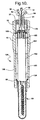
- FIG. 4 there is shown a second representative embodiment of a glow sensor according to the invention and generally indicated by numeral 60.
- the glow sensor 60 although appearing somewhat different, has many aspects of similarity to glow sensor 10 of FIG. 3 so that like reference numerals are used for like parts.
- Glow sensor 60 includes a metal shell 62 that is functionally similar to shell 12 of sensor 10 but is extended in length to a configuration suitable for installation in an open chamber engine as shown in FIG. 1, whereas glow sensor 10 of FIG. 3 is configured for installation in a pre-chamber engine as shown in FIG. 2 of the drawings.
- the metal shell 62 also supports a metal sheath 64. This sheath and its electrical connections could be of the non-isolated coil type shown in FIG. 3 but, in the present instance, is of an alternative isolated coil type, the construction of which is shown in FIG. 5 and will be subsequently described.
- the metal sheath 64 is supported and electrically isolated within the shell 62 by ceramic sleeves 40, 42, compression bushing 46 and sealing gasket 50 acting within an axial counterbore 44 and sealed by axial force applied by crimping the outer end 32 of the shell 62, all in the same manner as described with respect to glow sensor 10 of the first described embodiment.
- a ceramic sleeve 68 is received in a counterbore and retained by crimping the outer end 66 to support the outer end of the metal sheath 64 and assist in blocking the entry of combustion gases into the shell interior.
- Ceramic powder 70 preferably fills the annular space around the sheath 64 within the shell 62 and axially between the annular sleeve 68 and the outer ceramic sleeve 42.
- glow sheath 64 contains a center conductor 72 formed as a rod extending from adjacent the closed inner end 74 of the sheath upwardly through and out the open upper end of the sheath.
- a tubular sleeve of crushable high purity MgO insulation 76 Around the outer end of the insulation 76 is a conductive metal tube 78 which is spot welded at its inner end to a current regulating coil 80.
- Coil 80 is in turn welded at its inner end to a heating coil 82 and the inner end of the heating coil is reduced in diameter and welded to the inner end of the center conductor 72.
- MgO powder fills the inner end of the sheath 64 surrounding the connection of the center conductor 72 with the coil 82.
- An outer sleeve 84 of crushable MgO surrounds the coils 80, 82 and the tube 78, extending essentially the total length of the sheath 64.
- Annular openings at the open outer end of the sheath 64 are closed by rubber seals 86, 88 and the sheath with coils and insulation assembled therein is subsequently swaged, as previously referred to, causing the internal insulation to be crushed and packed tightly within the smaller diameter of the swaged sheath to hold the electrical conductors therein firmly in place within the sheath.
- the swaged sheath 64 then has a terminal 90 applied at the outer end of the center conductor 72 and insulated leads 92, 94 are connected with the conductive tube 78 and the metal glow sheath 64, respectively.
- the leads 92, 94 are provided with terminals 96, 98 respectively for connection to an electric power source.
- the swaged sheath assembly forms a glow sensor element which is then assembled into the shell 62.
- the insulation and support of the metal sheath 64 in the shell 62 is substantially the same as in the embodiment of FIG. 3 previously described.
- the electrical circuit feeding the glow heater coils 80, 82 is completely separate from the circuit through the sheath acting as the ion sensor electrode and grounded through the engine block and/or cylinder head. Since the isolated coils are completely separate from the sheath, their individual leads connect separately with a power source and, if desired, the voltage to the separate circuits may be differently controlled.
- Glow sensor 100 is quite similar to that of sensor 60 which comprises the embodiment of FIG. 4 so that like numerals are used for like parts.
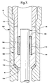
- Glow sensor 100 differs from that of sensor 60 primarily in the manner in which the glow sheath 64 is fixed within and electrically isolated from the metal shell 102 of the glow sensor.
- a ceramic sleeve 68 is crimped into a counterbore surrounding the sheath 64 as in the embodiment of FIG. 4. Adjacent the outer end 32, threads 16 and a hexagonal end 18 are provided as in the previously described embodiments.
- the outer end 32 of shell 102 is formed with a double or stepped counterbore 104, in the outer and smaller diameter portion of which is received a retainer 106, shown enlarged and in further detail in FIG. 7 of the drawings.
- the retainer 106 includes a tubular ceramic insulator 108 having a thickened inner portion 110 with a conical end 112 that engages a soft metal gasket 50 which is compressed against a conical seat 114 at the inner end of the counterbore 104.
- the outer portion of the ceramic insulator 108 has an enlarged inner diameter in which is received a sleeve-like metal ferrule 116 having an axially outer and radially inner edge 118 that is fixed to the metal sheath 64 by silver brazing or other suitable means.
- An axially inner and radially outer edge 120 of the metal ferrule 116 is fixed to the ceramic insulator 108 by silver-copper brazing or other suitable means.
- the inner diameter of the ferrule is relieved or enlarged in its axially inner portion to provide clearance for relative expansion of the heated sheath 64 within the ceramic insulator 108 which may be accommodated by flexing of the ferrule within the insulator.
- the brazing steps in assembly of the metal sheath to the ceramic insulator are preferably performed in an oven brazing operation.
- conductors 92, 94 and terminals 90, 96, 98 are attached.
- the sheath and retainer assembly is then installed in the metal shell 102 through its upper end.
- a tubular metal pusher 122 is installed engaging the upper end of the ceramic insulator 108.
- An outer end of the pusher is loaded with an axial force by crimping of the end 32 of the shell 102 against the pusher, thereby forcing the retainer 106 downward against the soft gasket 50 and compressing it to form a combustion gas seal between the insulator 108 and the shell 102.
- the brazing of the ferrule within the insulator 108 provides a combustion seal along the outer surface of the metal sheath 64.
- FIG. 8 there is shown a fourth embodiment of glow sensor generally indicated by numeral 130.
- Sensor 130 has a metal shell 132 that is similar to shell 102 of the previously described embodiment except that the internal diameter is essentially constant and the ends of the shell are not crimped.
- the sheath 64 is generally of the type shown in FIGS. 4 and 5, although other types of sheath interior constructions could be utilized and a sheath with non isolated coils could be used if desired. In any case, the inner end of the sheath is mechanically fixed within and electrically isolated from the outer end of the shell 132 by a retainer 133.
- the retainer comprises an assembly of a mounting tube 134 formed of a metal alloy or other suitable material and a glass seal 136 fixed within the tube 134 and directly engaging adjacent portions of the sheath 64.
- the glass seal 136 forms a combustion seal between the mounting tube 134 and sheath at the outer end.
- the retainer 133 is installed with a press fit within the outer end of the metal shell 132 to provide a gas seal between these two elements. Alternatively, the retainer could be brazed within the shell to form the gas seal.
- the sheath 64 connects with a snap on circular connector which is attached to the insulated lead 94 leading to terminal 98 for connection with a power source for the ion sensor function.
- the center conductor 72 leading to the heater coil connects at its outer end with terminal 90 as in the embodiment of FIG. 4.
- the conductive tube 78 connecting with the other side of the internal heater coils in the glow tip, connects at its upper end with insulated lead 92 which is in turn welded to the interior of the metal shell 132 inwardly of the rubber plug 30.
- lead 92 forms a ground connection with the shell internally of the glow sensor.
- the upper end of the sheath may have a glass seal of glass frit insulating and retaining the conductors within the sheath separate from the sheath and one another.
- Sensor 140 includes an inner retainer 133 comprising a shorter version of a mounting tube 134 having internally a glass ceramic seal 136.
- the tube 134 again has its lower portion pressed with an interference fit into the metal shell 144.
- this retainer is spaced axially outward from the inner end of the shell 144 to move the seal further away from the heat generated by the glow tip of the associated sheath 64.
- a sleeve 146 of ceramic insulation is inserted into the inner end of the metal shell 144 adjacent the retainer 133 to support and insulate the inner end of the sheath.
- a shorter insulating sleeve 148 is positioned immediately inward of sleeve 146 and has a conical surface engaging a combustion seal gasket 50 which engages a crimped inner end 150 of the metal shell to compress the gasket and retain the components in position while at the same time forming an outer diameter combustion seal.
- FIG. 10 there is shown a sixth embodiment of glow sensor according to the invention and generally indicated by numeral 154.
- Sensor 154 is similar in general construction to the sensors previously described, differing primarily in the form of insulation and support provided for the sheath 64 within the metal shell 156.
- the insulation involves ceramic sleeve elements alternately spaced with packed talc or ceramic powder packed between the sheath 64 and the shell 156.
- the insulating means of sensor 154 includes an inner end ceramic sleeve 158 having a stepped outer diameter with a conical surface that engages a soft metallic sealing gasket 50 which acts as an outer diameter combustion gas seal.
- Outward of sleeve 158 is a packed annular mass of ceramic powder 160.
- This powder pack is engaged by a ceramic spacer 162 which in turn engages another annular mass of packed ceramic powder 164.
- a second ceramic spacer 166 is mounted outward of powder pack 164 but inward of the outer end of the metal shell 156.
- a rubber seal 168 is pressed against the outer end of the spacer 166 by a tubular metal pusher 170 that is held in place within the shell by crimping its outer end 32 as in some of the previously described embodiments.
Landscapes
- Engineering & Computer Science (AREA)
- Chemical & Material Sciences (AREA)
- Combustion & Propulsion (AREA)
- Mechanical Engineering (AREA)
- General Engineering & Computer Science (AREA)
- Ignition Installations For Internal Combustion Engines (AREA)
- Testing Of Engines (AREA)
Applications Claiming Priority (2)
| Application Number | Priority Date | Filing Date | Title |
|---|---|---|---|
| US16039898A | 1998-09-25 | 1998-09-25 | |
| US160398 | 1998-09-25 |
Publications (2)
| Publication Number | Publication Date |
|---|---|
| EP0989370A2 true EP0989370A2 (de) | 2000-03-29 |
| EP0989370A3 EP0989370A3 (de) | 2005-04-20 |
Family
ID=22576742
Family Applications (1)
| Application Number | Title | Priority Date | Filing Date |
|---|---|---|---|
| EP99203034A Withdrawn EP0989370A3 (de) | 1998-09-25 | 1999-09-17 | Metallspitze für Glühsensor |
Country Status (1)
| Country | Link |
|---|---|
| EP (1) | EP0989370A3 (de) |
Cited By (11)
| Publication number | Priority date | Publication date | Assignee | Title |
|---|---|---|---|---|
| EP1041343A1 (de) * | 1999-03-31 | 2000-10-04 | Beru AG | Verfahren zum abdichtenden Verschliessen des Anschlussseitigen Endbereichs des Glührohres einer Glühkerze und Glühkerzen mit verfahrensgemässem Verschluss |
| EP1162407A1 (de) * | 2000-08-11 | 2001-12-12 | Federal-Mogul Ignition Srl | Glühkerze für Brennkraftmaschinen |
| US6392199B1 (en) * | 1999-05-05 | 2002-05-21 | Beru Ag | Glow plug and process for its manufacture |
| EP1243858A1 (de) | 2001-03-14 | 2002-09-25 | Federal-Mogul Ignition Srl | Glühkerze zur Messung des Ionisationsstromes einer Kraftmaschine |
| EP1243859A1 (de) * | 2001-03-14 | 2002-09-25 | Federal-Mogul Ignition Srl | Glühkerze zur Messung des Ionisationsstromes einer Kraftmaschine und sein Herstellungsverfahren |
| DE10248045B4 (de) * | 2001-10-16 | 2010-06-17 | DENSO CORPORATION, Kariya-shi | Glühkerze |
| EP2886960A1 (de) * | 2013-12-23 | 2015-06-24 | SIEVA d.o.o., PE Spodnja Idrija | Heizstab mit keramischer Innenhülse, Glühkerze und Herstellungsverfahren dafür |
| JP5806211B2 (ja) * | 2011-01-25 | 2015-11-10 | 日本特殊陶業株式会社 | グロープラグ |
| JP2018100804A (ja) * | 2016-12-21 | 2018-06-28 | 京セラ株式会社 | ヒータ |
| CN108798965A (zh) * | 2018-06-12 | 2018-11-13 | 中国煤炭科工集团太原研究院有限公司 | 一种矿用防爆柴油机低温辅助启动装置 |
| CN108869139A (zh) * | 2018-06-12 | 2018-11-23 | 中国煤炭科工集团太原研究院有限公司 | 一种矿用防爆柴油机低温辅助启动装置的制备方法 |
Citations (4)
| Publication number | Priority date | Publication date | Assignee | Title |
|---|---|---|---|---|
| US4760830A (en) * | 1981-07-23 | 1988-08-02 | Ambac Industries, Incorporated | Method and apparatus for controlling fuel injection timing in a compression ignition engine |
| DE19737396A1 (de) * | 1996-09-12 | 1998-03-19 | Denso Corp | Glühkerze |
| JPH1089223A (ja) * | 1996-09-11 | 1998-04-07 | Denso Corp | グロープラグ |
| JPH1089687A (ja) * | 1996-09-18 | 1998-04-10 | Denso Corp | グロープラグ |
-
1999
- 1999-09-17 EP EP99203034A patent/EP0989370A3/de not_active Withdrawn
Patent Citations (4)
| Publication number | Priority date | Publication date | Assignee | Title |
|---|---|---|---|---|
| US4760830A (en) * | 1981-07-23 | 1988-08-02 | Ambac Industries, Incorporated | Method and apparatus for controlling fuel injection timing in a compression ignition engine |
| JPH1089223A (ja) * | 1996-09-11 | 1998-04-07 | Denso Corp | グロープラグ |
| DE19737396A1 (de) * | 1996-09-12 | 1998-03-19 | Denso Corp | Glühkerze |
| JPH1089687A (ja) * | 1996-09-18 | 1998-04-10 | Denso Corp | グロープラグ |
Non-Patent Citations (2)
| Title |
|---|
| PATENT ABSTRACTS OF JAPAN vol. 1998, no. 09, 31 July 1998 (1998-07-31) & JP 10 089223 A (DENSO CORP), 7 April 1998 (1998-04-07) * |
| PATENT ABSTRACTS OF JAPAN vol. 1998, no. 09, 31 July 1998 (1998-07-31) & JP 10 089687 A (DENSO CORP), 10 April 1998 (1998-04-10) * |
Cited By (18)
| Publication number | Priority date | Publication date | Assignee | Title |
|---|---|---|---|---|
| US6252200B1 (en) | 1999-03-31 | 2001-06-26 | Beru Ag | Process for sealing the terminal-side end area of the glow tube of a glow plug and glow plugs with a seal as claimed in the process |
| EP1041343A1 (de) * | 1999-03-31 | 2000-10-04 | Beru AG | Verfahren zum abdichtenden Verschliessen des Anschlussseitigen Endbereichs des Glührohres einer Glühkerze und Glühkerzen mit verfahrensgemässem Verschluss |
| US6392199B1 (en) * | 1999-05-05 | 2002-05-21 | Beru Ag | Glow plug and process for its manufacture |
| US6459072B1 (en) | 2000-08-11 | 2002-10-01 | Federal-Mogul Ignition Srl | Glow plug for internal combustion engines |
| EP1162407A1 (de) * | 2000-08-11 | 2001-12-12 | Federal-Mogul Ignition Srl | Glühkerze für Brennkraftmaschinen |
| US6646229B2 (en) | 2001-03-14 | 2003-11-11 | Federal-Mogul Ignition Srl | Glow plug arranged for measuring the ionization current of an engine |
| EP1243859A1 (de) * | 2001-03-14 | 2002-09-25 | Federal-Mogul Ignition Srl | Glühkerze zur Messung des Ionisationsstromes einer Kraftmaschine und sein Herstellungsverfahren |
| US6646230B2 (en) | 2001-03-14 | 2003-11-11 | Federal-Mogul Ignition Srl | Glow plug arranged for measuring the ionization current of an engine, and method for manufacturing the same |
| EP1243858A1 (de) | 2001-03-14 | 2002-09-25 | Federal-Mogul Ignition Srl | Glühkerze zur Messung des Ionisationsstromes einer Kraftmaschine |
| DE10248045B4 (de) * | 2001-10-16 | 2010-06-17 | DENSO CORPORATION, Kariya-shi | Glühkerze |
| JP5806211B2 (ja) * | 2011-01-25 | 2015-11-10 | 日本特殊陶業株式会社 | グロープラグ |
| EP2886960A1 (de) * | 2013-12-23 | 2015-06-24 | SIEVA d.o.o., PE Spodnja Idrija | Heizstab mit keramischer Innenhülse, Glühkerze und Herstellungsverfahren dafür |
| WO2015097044A1 (en) * | 2013-12-23 | 2015-07-02 | Sieva D.O.O.,Pe Spodnja Idrija | Heating rod comprising a ceramic internal sleeve, glow plug and method for manufacturing the same |
| JP2018100804A (ja) * | 2016-12-21 | 2018-06-28 | 京セラ株式会社 | ヒータ |
| CN108798965A (zh) * | 2018-06-12 | 2018-11-13 | 中国煤炭科工集团太原研究院有限公司 | 一种矿用防爆柴油机低温辅助启动装置 |
| CN108869139A (zh) * | 2018-06-12 | 2018-11-23 | 中国煤炭科工集团太原研究院有限公司 | 一种矿用防爆柴油机低温辅助启动装置的制备方法 |
| CN108869139B (zh) * | 2018-06-12 | 2020-08-18 | 中国煤炭科工集团太原研究院有限公司 | 一种矿用防爆柴油机低温辅助启动装置的制备方法 |
| CN108798965B (zh) * | 2018-06-12 | 2021-02-02 | 中国煤炭科工集团太原研究院有限公司 | 一种矿用防爆柴油机低温辅助启动装置 |
Also Published As
| Publication number | Publication date |
|---|---|
| EP0989370A3 (de) | 2005-04-20 |
Similar Documents
| Publication | Publication Date | Title |
|---|---|---|
| US5589091A (en) | Glow plug with prestressed contact surfaces | |
| EP2342788B1 (de) | Zünder für eine luft/kraftstoff-mischung und motor damit sowie verfahren zu seiner montage in einem zylinderkopf | |
| EP2127048B1 (de) | 14-mm-zündkerze mit verlängerung | |
| US7059926B2 (en) | Method of making a spark plug having a multi-tiered center wire assembly | |
| KR100427818B1 (ko) | 세라믹히터 | |
| US4477717A (en) | Fast start glow plug | |
| US4563568A (en) | Diesel engine glow plug | |
| EP0989370A2 (de) | Metallspitze für Glühsensor | |
| US6512204B1 (en) | Ion sensor glow plug assembly | |
| US20130049566A1 (en) | Corona igniter including temperature control features | |
| US6062185A (en) | Glow sensor and engine component combination | |
| US4661686A (en) | Dual line ceramic glow plug | |
| US6144015A (en) | Glow sensor--ceramic flat plate | |
| US7944135B2 (en) | Spark plug and methods of construction thereof | |
| US20040079139A1 (en) | Ignition apparatus for internal combustion engine | |
| JP2009545856A (ja) | 一体型のシェルの高位置にねじ部を有するスパークプラグ | |
| JP2002525555A (ja) | シース形セラミックグロープラグ | |
| US6215105B1 (en) | Ion sensor glow plug assembly with coating between sheath and shell | |
| US6248980B1 (en) | Ion sensor glow plug assembly | |
| JP2002526737A (ja) | セラミック製のシース形グロープラグ | |
| US6285007B1 (en) | Ion sensor glow plug assembly | |
| EP0989367B1 (de) | Keramische Spitze für Glühsensor | |
| US4592134A (en) | Glow plug | |
| US8680758B2 (en) | Spark plug having a plastic upper insulator and method of construction | |
| JP3754529B2 (ja) | 自己制御型セラミックヒータ |
Legal Events
| Date | Code | Title | Description |
|---|---|---|---|
| PUAI | Public reference made under article 153(3) epc to a published international application that has entered the european phase |
Free format text: ORIGINAL CODE: 0009012 |
|
| AK | Designated contracting states |
Kind code of ref document: A2 Designated state(s): AT BE CH CY DE DK ES FI FR GB GR IE IT LI LU MC NL PT SE |
|
| AX | Request for extension of the european patent |
Free format text: AL;LT;LV;MK;RO;SI |
|
| PUAL | Search report despatched |
Free format text: ORIGINAL CODE: 0009013 |
|
| AK | Designated contracting states |
Kind code of ref document: A3 Designated state(s): AT BE CH CY DE DK ES FI FR GB GR IE IT LI LU MC NL PT SE |
|
| AX | Request for extension of the european patent |
Extension state: AL LT LV MK RO SI |
|
| RIC1 | Information provided on ipc code assigned before grant |
Ipc: 7F 23Q 7/00 A |
|
| 17P | Request for examination filed |
Effective date: 20051020 |
|
| AKX | Designation fees paid |
Designated state(s): DE FR GB |
|
| 17Q | First examination report despatched |
Effective date: 20060911 |
|
| STAA | Information on the status of an ep patent application or granted ep patent |
Free format text: STATUS: THE APPLICATION IS DEEMED TO BE WITHDRAWN |
|
| 18D | Application deemed to be withdrawn |
Effective date: 20070123 |