EP0989238B1 - Traffic sign with vertically movable light source - Google Patents
Traffic sign with vertically movable light source Download PDFInfo
- Publication number
- EP0989238B1 EP0989238B1 EP99115836A EP99115836A EP0989238B1 EP 0989238 B1 EP0989238 B1 EP 0989238B1 EP 99115836 A EP99115836 A EP 99115836A EP 99115836 A EP99115836 A EP 99115836A EP 0989238 B1 EP0989238 B1 EP 0989238B1
- Authority
- EP
- European Patent Office
- Prior art keywords
- holder
- housing
- traffic sign
- support ring
- elastic support
- Prior art date
- Legal status (The legal status is an assumption and is not a legal conclusion. Google has not performed a legal analysis and makes no representation as to the accuracy of the status listed.)
- Expired - Lifetime
Links
- 230000035939 shock Effects 0.000 claims description 7
- 239000000463 material Substances 0.000 claims description 3
- 238000005461 lubrication Methods 0.000 claims 1
- 229920003023 plastic Polymers 0.000 description 15
- 238000004073 vulcanization Methods 0.000 description 6
- 238000010276 construction Methods 0.000 description 5
- 230000002093 peripheral effect Effects 0.000 description 5
- 229910052751 metal Inorganic materials 0.000 description 3
- 239000002184 metal Substances 0.000 description 3
- 238000007789 sealing Methods 0.000 description 3
- 239000004519 grease Substances 0.000 description 2
- 229910052782 aluminium Inorganic materials 0.000 description 1
- XAGFODPZIPBFFR-UHFFFAOYSA-N aluminium Chemical compound [Al] XAGFODPZIPBFFR-UHFFFAOYSA-N 0.000 description 1
- 239000004568 cement Substances 0.000 description 1
- 230000006835 compression Effects 0.000 description 1
- 238000007906 compression Methods 0.000 description 1
- 230000008878 coupling Effects 0.000 description 1
- 238000010168 coupling process Methods 0.000 description 1
- 238000005859 coupling reaction Methods 0.000 description 1
- 230000005489 elastic deformation Effects 0.000 description 1
- XUCNUKMRBVNAPB-UHFFFAOYSA-N fluoroethene Chemical group FC=C XUCNUKMRBVNAPB-UHFFFAOYSA-N 0.000 description 1
- 238000009499 grossing Methods 0.000 description 1
- 238000009434 installation Methods 0.000 description 1
- 230000004048 modification Effects 0.000 description 1
- 238000012986 modification Methods 0.000 description 1
- 239000004033 plastic Substances 0.000 description 1
- 239000011347 resin Substances 0.000 description 1
- 229920005989 resin Polymers 0.000 description 1
- 239000012780 transparent material Substances 0.000 description 1
Images



Classifications
-
- F—MECHANICAL ENGINEERING; LIGHTING; HEATING; WEAPONS; BLASTING
- F21—LIGHTING
- F21V—FUNCTIONAL FEATURES OR DETAILS OF LIGHTING DEVICES OR SYSTEMS THEREOF; STRUCTURAL COMBINATIONS OF LIGHTING DEVICES WITH OTHER ARTICLES, NOT OTHERWISE PROVIDED FOR
- F21V15/00—Protecting lighting devices from damage
- F21V15/04—Resilient mountings, e.g. shock absorbers
-
- E—FIXED CONSTRUCTIONS
- E01—CONSTRUCTION OF ROADS, RAILWAYS, OR BRIDGES
- E01F—ADDITIONAL WORK, SUCH AS EQUIPPING ROADS OR THE CONSTRUCTION OF PLATFORMS, HELICOPTER LANDING STAGES, SIGNS, SNOW FENCES, OR THE LIKE
- E01F9/00—Arrangement of road signs or traffic signals; Arrangements for enforcing caution
- E01F9/50—Road surface markings; Kerbs or road edgings, specially adapted for alerting road users
- E01F9/553—Low discrete bodies, e.g. marking blocks, studs or flexible vehicle-striking members
- E01F9/559—Low discrete bodies, e.g. marking blocks, studs or flexible vehicle-striking members illuminated
-
- E—FIXED CONSTRUCTIONS
- E01—CONSTRUCTION OF ROADS, RAILWAYS, OR BRIDGES
- E01F—ADDITIONAL WORK, SUCH AS EQUIPPING ROADS OR THE CONSTRUCTION OF PLATFORMS, HELICOPTER LANDING STAGES, SIGNS, SNOW FENCES, OR THE LIKE
- E01F9/00—Arrangement of road signs or traffic signals; Arrangements for enforcing caution
- E01F9/50—Road surface markings; Kerbs or road edgings, specially adapted for alerting road users
- E01F9/553—Low discrete bodies, e.g. marking blocks, studs or flexible vehicle-striking members
- E01F9/565—Low discrete bodies, e.g. marking blocks, studs or flexible vehicle-striking members having deflectable or displaceable parts
- E01F9/571—Low discrete bodies, e.g. marking blocks, studs or flexible vehicle-striking members having deflectable or displaceable parts displaceable vertically under load, e.g. in combination with rotation
-
- F—MECHANICAL ENGINEERING; LIGHTING; HEATING; WEAPONS; BLASTING
- F21—LIGHTING
- F21S—NON-PORTABLE LIGHTING DEVICES; SYSTEMS THEREOF; VEHICLE LIGHTING DEVICES SPECIALLY ADAPTED FOR VEHICLE EXTERIORS
- F21S8/00—Lighting devices intended for fixed installation
- F21S8/02—Lighting devices intended for fixed installation of recess-mounted type, e.g. downlighters
- F21S8/022—Lighting devices intended for fixed installation of recess-mounted type, e.g. downlighters intended to be recessed in a floor or like ground surface, e.g. pavement or false floor
-
- F—MECHANICAL ENGINEERING; LIGHTING; HEATING; WEAPONS; BLASTING
- F21—LIGHTING
- F21S—NON-PORTABLE LIGHTING DEVICES; SYSTEMS THEREOF; VEHICLE LIGHTING DEVICES SPECIALLY ADAPTED FOR VEHICLE EXTERIORS
- F21S9/00—Lighting devices with a built-in power supply; Systems employing lighting devices with a built-in power supply
- F21S9/02—Lighting devices with a built-in power supply; Systems employing lighting devices with a built-in power supply the power supply being a battery or accumulator
- F21S9/03—Lighting devices with a built-in power supply; Systems employing lighting devices with a built-in power supply the power supply being a battery or accumulator rechargeable by exposure to light
-
- F—MECHANICAL ENGINEERING; LIGHTING; HEATING; WEAPONS; BLASTING
- F21—LIGHTING
- F21V—FUNCTIONAL FEATURES OR DETAILS OF LIGHTING DEVICES OR SYSTEMS THEREOF; STRUCTURAL COMBINATIONS OF LIGHTING DEVICES WITH OTHER ARTICLES, NOT OTHERWISE PROVIDED FOR
- F21V31/00—Gas-tight or water-tight arrangements
- F21V31/005—Sealing arrangements therefor
-
- Y—GENERAL TAGGING OF NEW TECHNOLOGICAL DEVELOPMENTS; GENERAL TAGGING OF CROSS-SECTIONAL TECHNOLOGIES SPANNING OVER SEVERAL SECTIONS OF THE IPC; TECHNICAL SUBJECTS COVERED BY FORMER USPC CROSS-REFERENCE ART COLLECTIONS [XRACs] AND DIGESTS
- Y02—TECHNOLOGIES OR APPLICATIONS FOR MITIGATION OR ADAPTATION AGAINST CLIMATE CHANGE
- Y02B—CLIMATE CHANGE MITIGATION TECHNOLOGIES RELATED TO BUILDINGS, e.g. HOUSING, HOUSE APPLIANCES OR RELATED END-USER APPLICATIONS
- Y02B20/00—Energy efficient lighting technologies, e.g. halogen lamps or gas discharge lamps
- Y02B20/72—Energy efficient lighting technologies, e.g. halogen lamps or gas discharge lamps in street lighting
Definitions
- the present invention relates in general to traffic signs which issue traffic signals for achieving the safety passage of motor vehicles running on roads, and more particularly to traffic signs of a type which is mounted on a paved road. More specifically, the present invention is concerned with the traffic signs of a type having a sinkable light source for protecting the light source when a snow removing vehicle or the like runs over the sign.
- the traffic sign of the publication comprises a bottomed cylindrical housing 1 which is laid under a paved road surface "r".
- a circular elastic member 2 is put on the bottom of the housing 1 and a projected member 3 is put on the circular elastic member 2.
- a reflector holder 4 constructed of a transparent material is mounted on the projected member 3.
- the reflector holder 4 comprises a flat bottom wall 4a and a convex upper wall 5 which is integrally projected from a periphery of the flat bottom wall 4a.
- the convex upper wall 5 is projected upward beyond the paved road surface "r” and has a plurality of light reflecting plates 6 embedded in a slanted wall part 5a of the wall 5.
- An elastically deformable annular gasket 7 is arranged with its inner peripheral portion resiliently disposed between the projected member 3 and the flat bottom wall 4a of the reflector holder 4.
- a biasing spring is used for biasing a light reflector upward. That is, when the snow removing vehicle runs on the light reflector, the light reflector is moved down against the biasing force of the spring. Once the vehicle passes through the light reflector, the reflector is moved up to its projected normal position.
- US-A-3 703 855 discloses a traffic sign comprising a housing having an open upper end, a holder vertically movably received in said housing, and a light emitting unit installed in said holder to move therewith.
- a space is defined between a bottom of said housing and a lower end of said holder to permit the vertical movement of said holder in said housing.
- An elastic support ring having an inner wall fixed to an outer surface of said holder and an outer wall fixed to an inner surface of said housing is provided.
- a traffic sign which comprises a housing having an open upper end; a holder vertically movably received in the housing; a light emitting unit installed in the holder to move therewith; a transparent plate mounted on the holder to move therewith, the transparent plate permitting a light from said light emitting unit to transmit therethrough; a space defined between a bottom of the housing and a lower end of the holder to permit the vertical movement of the holder in the housing; an elastic support ring having an inner wall fixed to an outer surface of the holder and an outer wall fixed to an inner surface of the housing; projections formed on the elastic support ring, each projection being projected upward so that each projection is higher than an upper flat surface of the transparent plate; and recesses provided by the elastic support ring, each recess being defined between the projections, so that the light from the light emitting unit is viewed through the transparent plate and each of the recesses.
- a traffic sign 100A which is a first embodiment of the present invention.
- the traffic sign of the invention is of a type which has a light source which is vertically movably installed therein.
- the traffic sign 100A comprises generally a bottomed cylindrical housing 11 which is laid under a paved road surface "r", a cylindrical holder 12 which is vertically movably received in the housing 11 and has a light emitting unit 13 installed therein, an elastic support ring 14 which is made of rubber material and disposed between the housing 11 and the holder 12 to resiliently support the holder 12 on the housing 11, two arcuate projected portions 15 (see Fig. 4) which are integrally formed on the elastic support ring 14 and two arcuate recesses 16 (see Fig. 4) which are each defined between the arcuate projected portions 15.
- the two arcuate projected portions 15 are provided at diametrically opposed positions of the elastic support ring 14, and the two arcuate recesses 16 are also provided at diametrically opposed positions of the support ring 14.
- the housing 11 is constructed of a metal such as aluminum or the like.
- the housing 11 comprises a circular lower part 17 fitted in a bore "X" provided in the paved road "R”, and an annular upper part 18 concentrically mounted on and fixed to the lower part 17 by means of four connecting bolts 19.
- the circular lower part 17 is formed with a circular recess which comprises a smaller diameter lower portion 17a and a larger diameter upper portion 17b which are merged. Thus, an annular step (no numeral) is defined between these two portions 17a and 17b, as shown.
- the circular lower part 17 is formed at its outer surface with diametrically extending bores 17c into which part of the paved road "R" (viz., cement) is inserted for achieving an assured connection of the lower part 17 to the paved road "R".
- the annular upper part 18 has an inner diameter somewhat larger than the diameter of the larger diameter upper portion 17b of the lower part 17, and has a small annular groove 18a around an inner lower peripheral wall thereof.
- the holder 12 comprises a holder proper 20 constructed of a metal or plastic, an apertured circular seat member 21 disposed on an upper portion 20a of the holder proper 20, and a circular transparent plastic plate 22 mounted on the sheet member 21.
- a holder proper 20 constructed of a metal or plastic
- an apertured circular seat member 21 disposed on an upper portion 20a of the holder proper 20
- a circular transparent plastic plate 22 mounted on the sheet member 21.
- four connecting bolts 23 are used in the illustrated manner.
- the holder proper 20 is formed with a rectangular recess 20b which has a holding case 24 tightly installed therein.
- a light emitting unit 13 (see Fig. 4) that comprises a solar battery 13a, a plurality of lamps 13b and a light collecting portion 13c.
- a cylindrical space 25 which permits upward and downward movement of the holder 12.
- the outer diameter of the lower end portion 20c of the holder proper 20 is somewhat smaller than the diameter of the smaller diameter lower recess 17a, so that there is defined between the outer cylindrical wall of the lower end portion 20c and the inner cylindrical wall of the lower recess 17a a thin cylindrical space 26 which can guides the upward and downward movement of the holder 12.
- a rubber cap ( 27 + 28) consisting of a cylindrical part 27 and a thicker circular part 28 is concentrically put on the lower end portion 20c of the holder proper 20.
- the cylindrical part 27 is intimately put on the outer cylindrical wall of the lower end portion 20c and the circular part 28 is intimately put on the circular lower end of the holder proper 20.
- the two parts 27 and 28 are bonded through vulcanization. Due to provision of this rubber cap, collision of the holder proper 20 against the inner cylindrical wall of the smaller diameter lower recess 17a and that against the bottom wall 17d of the lower recess 17a are damped.
- a grease 29 for smoothing the upward and downward movement of the holder 12 in the housing 11.
- a sheet of fluoroethylene resin may be applied to the part 27.
- the apertured circular seat member 21 is constructed of a metal.
- the seat member 21 has a radially outer portion with a generally T-shaped cross section and comprises a horizontal flat part 21a which is sandwiched between the holder proper 20 and the transparent plastic plate 22 and an annular vertical flange part 21b which is integrally formed on an outer periphery of the flat part 21a to hold the outer periphery of the upper portion 20a of the holder proper 20 and that of the transparent plastic plate 22.
- the horizontal flat part 21a of the seat member 21 is formed on its upper surface with an annular groove for receiving therein a seal member 30. With this seal member 30, a hermetical sealing between the horizontal flat part 21a and the transparent plastic plate 22 is achieved. That is, the interior of the holding case 24 is hermetically isolated.
- the elastic support ring 14 is concentrically interposed between the annular upper part 18 of the housing 11 and the annular vertical flange part 21b of the seat member 21.
- the support ring 14 upon assembly, has a reversed U-shaped cross section leaving a concave recess 31 on a lower side thereof.
- the elastic support ring 14 has an inner peripheral portion 14a bonded via vulcanization to the annular vertical flange part 21b and an outer peripheral portion 14b bonded via vulcanization to the annular upper part 18.
- An upper flat portion 14c of the support ring 14 is shaped and arranged to be lower than an upper flat surface 22a of the transparent plastic plate 22.
- the upper flat portion 14c defines a bottom of the arcuate recess 16.
- the outer peripheral portion 14b of the support ring 14 has a lower flange 32 pressed in the annular groove 18a of the annular upper part 18 of the housing 11. With the lower flange 32, hermetic sealing between the lower and upper parts 17 and 18 of the housing 11 is assured.
- each projected portion 15 has a top 15a higher than the upper flat surface 22a of the transparent plastic plate 22 and has a tapered outer surface 15b whose height gradually increases with reduction in distance to a center of the support ring 14. Between each projected portion 15 and the annular vertical flange part 21b of the seat member 21, there is defined an arcuate groove 33.
- the description will be commenced with respect to a normal condition of the traffic sign 100A.
- the holder 12 in the housing 11 assumes its uppermost position projecting the projected portions 15 of the elastic support ring 14 and the transparent plastic plate 22 upward beyond the road surface "r".
- the upper part of the transparent plate 22 is viewed from the longitudinal directions of the road "R" through the arcuate recesses 16 of the support ring 14. That is, the light produced by the light emitting unit 13 and emitted from the transparent plastic plate 22 can be viewed by a driver on a motor vehicle running on the road surface "r".
- the snow removing blade 8 rides on the tapered outer surface 15b of the projected portions 15, the holder 12 is inclined but slightly relative to the housing 11 while sliding downward using the inner cylindrical surface of the smaller diameter lower portion 17a as a guide.
- a chamber including the concave recess 31 (see Fig. 1), the lower and upper portions 17a and 17b and the think cylindrical space 26 can act as an air cushion, which smoothes and dampens the movements.
- the entire of the holder 12 is moved down and fully put in the housing 11 preventing the transparent plastic plate 22 from being damaged by the blade 8. Due to provision of the annular grooves 33 (see Figs. 1 and 5), the elastic deformation of the projected portions 15 is smoothly carried out, which avoids application of excessive load to the entire structure of the elastic support ring 14 and thus allows the ring 14 to have a longer life. Due to the elasticity possessed by the ring 14, the shock applied to the ring 14 by the blade 8 is dampened thereby smoothly starting the downward movement of the holder 12.
- the thicker circular part 28 made of rubber material, a shock produced when, under downward movement, the holder 12 collides against a bottom wall 17d of the recess of the circular lower part 17 is appropriately dampened. Furthermore, because the elastic support ring 14 is bonded via vulcanization to both the annular upper part 18 of the housing 11 and the circular seat member 21, the work for assembling the traffic sign 100A is facilitated. Furthermore, due to such bonding, the sealing to the air cushion chamber (viz., the chamber including the portions 31, 17b, 17a and 26) is improved.
- a traffic sign 100B which is a second embodiment of the present invention.
- a single unit housing 11 is used, which has the holder 12 vertically movably held therein.
- An annular seat member 34 is used as a substitute for the apertured circular seat member 21.
- the annular seat member 34 holds the outer periphery of the upper portion 20a of the holder proper 20 and that of the transparent plastic plate 22.
- the annular seat member 34 has an inwardly bent lower flange 34a to press a seal ring 36 against the upper portion 20a of the holder proper 20.
- Another annular seat member 18A is used, which is disposed within an upper part of the single unit housing 11. To these two seat members 34 and 18A, the elastic support ring 14 are bonded via vulcanization, like in case of the above-mentioned first embodiment.
- a traffic sign 100C which is a third embodiment of the present invention.
- the upper portion 20a of the holder proper 20 is formed with a circular recess 20d in which the transparent plastic plate 22 is put. Furthermore, the elastic supporting ring 14 and the rubber cap (27 + 28) are integral with each other, and there is no means corresponding to the annular seat member 34 employed in the second embodiment 100B. In this third embodiment 100C, the integral structure is bonded to the outer surface of the holder proper 20 via vulcanization.
- a traffic sign 100D which is a fourth embodiment of the present invention.
- this fourth embodiment 100D there is no means corresponding to the circular recess 20d employed in the third embodiment 100C, and the arcuate groove 33 defined between each projected portion 15 of the elastic support ring 14 and the periphery of the transparent plastic plate 22 is formed large as compared with that in the third embodiment.
- a traffic sign 100E which is a fifth embodiment of the present invention.
- a conical elastic support ring 14 is employed, which has an inner cylindrical wall bonded to the annular vertical flange part 21b of seat member 21 and an outer cylindrical wall bonded to the annular seat member 18A. Furthermore, in this fifth embodiment 100E, each arcuate projected portion 15 has a peaked top.
Landscapes
- Engineering & Computer Science (AREA)
- General Engineering & Computer Science (AREA)
- Architecture (AREA)
- Civil Engineering (AREA)
- Structural Engineering (AREA)
- Road Signs Or Road Markings (AREA)
- Illuminated Signs And Luminous Advertising (AREA)
- Traffic Control Systems (AREA)
Abstract
Description
- The present invention relates in general to traffic signs which issue traffic signals for achieving the safety passage of motor vehicles running on roads, and more particularly to traffic signs of a type which is mounted on a paved road. More specifically, the present invention is concerned with the traffic signs of a type having a sinkable light source for protecting the light source when a snow removing vehicle or the like runs over the sign.
- Hitherto, various types of traffic signs of the above-mentioned type have been proposed and put into practical use.
- For clarifying the task of the present invention, exemplified two of the conventional traffic signs of such type will be briefly described in the following.
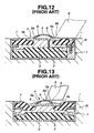
- One is a traffic sign described in Japanese Patent Second Provisional Publication 59-122612, which will be described with reference to Figs. 12 and 13 of the accompanying drawings.
- As is seen from Fig. 12, the traffic sign of the publication comprises a bottomed
cylindrical housing 1 which is laid under a paved road surface "r". A circularelastic member 2 is put on the bottom of thehousing 1 and a projectedmember 3 is put on the circularelastic member 2. Areflector holder 4 constructed of a transparent material is mounted on the projectedmember 3. Thereflector holder 4 comprises aflat bottom wall 4a and a convexupper wall 5 which is integrally projected from a periphery of theflat bottom wall 4a. As shown, the convexupper wall 5 is projected upward beyond the paved road surface "r" and has a plurality oflight reflecting plates 6 embedded in aslanted wall part 5a of thewall 5. An elastically deformableannular gasket 7 is arranged with its inner peripheral portion resiliently disposed between the projectedmember 3 and theflat bottom wall 4a of thereflector holder 4. - When now as is seen from Figs. 12 and 13, a snow removing vehicle running on the road surface "r" comes to a position to have its
snow removing blade 8 collide against the convexupper wall 5, the convexupper wall 5 becomes sunken due to the flexibility possessed by theannular gasket 7 and the compressibility possessed by the circularelastic member 2. After thesnow removing blade 8 passes through the convexupper wall 5, theupper wall 5 is returned back to its projected normal position due to the return force of thegasket 7 and theelastic member 2. In this normal position of the convexupper wall 5, thelight reflecting plates 6 can be viewed from the road surface "r". Due to the vertical mobility of the convexupper wall 5, undesired breakage of the same is avoided. - The other is a traffic sign described in Japanese Patent Second Provisional Publication 9-158135. In the sign of this publication, a biasing spring is used for biasing a light reflector upward. That is, when the snow removing vehicle runs on the light reflector, the light reflector is moved down against the biasing force of the spring. Once the vehicle passes through the light reflector, the reflector is moved up to its projected normal position.
- However, even the above-mentioned two traffic signs have failed to exhibit satisfied performance due to their inherent constructions. That is, in the former sign, the convex
upper wall 5, especially, theslanted wall part 5a of the same tends to loose its transparency due to repeated attacks by snow removing vehicles. If the transparency is severely lowered, thelight reflecting plates 6 can not effectively reflect a light. In the latter sign, the biasing spring tends to loose its resiliency due to the repeated compression and expansion movements. - US-A-3 703 855 discloses a traffic sign comprising a housing having an open upper end, a holder vertically movably received in said housing, and a light emitting unit installed in said holder to move therewith. A space is defined between a bottom of said housing and a lower end of said holder to permit the vertical movement of said holder in said housing. An elastic support ring having an inner wall fixed to an outer surface of said holder and an outer wall fixed to an inner surface of said housing is provided.
- It is therefore an object of the present invention to provided a traffic sign with a vertically movable light source, which is free of the above-mentioned drawbacks.
- According to a first aspect of the present invention, there is provided a traffic sign which comprises a housing having an open upper end; a holder vertically movably received in the housing; a light emitting unit installed in the holder to move therewith; a transparent plate mounted on the holder to move therewith, the transparent plate permitting a light from said light emitting unit to transmit therethrough; a space defined between a bottom of the housing and a lower end of the holder to permit the vertical movement of the holder in the housing; an elastic support ring having an inner wall fixed to an outer surface of the holder and an outer wall fixed to an inner surface of the housing; projections formed on the elastic support ring, each projection being projected upward so that each projection is higher than an upper flat surface of the transparent plate; and recesses provided by the elastic support ring, each recess being defined between the projections, so that the light from the light emitting unit is viewed through the transparent plate and each of the recesses.
- Other objects and advantages of the present invention will become apparent from the following description when taken in conjunction with the accompanying drawings, in which:
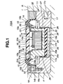
- Fig. 1 is a sectional view of a traffic sign which is a first embodiment of the present invention and a view taken along the line "A-A" of Fig. 4;
- Fig. 2 is a sectional view of the first embodiment, taken along the line "B-B" of Fig. 4;
- Fig. 3 is a partial view taken from the direction of the arrow "C" of Fig. 4;
- Fig. 4 is a plan view of the traffic sign of the first embodiment;
- Figs. 5, 6 and 7 are views similar to Fig. 1, but showing different operation conditions of the first embodiment;
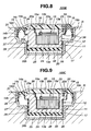
- Fig. 8 is a sectional view of a traffic sign which is a second embodiment of the present invention;
- Fig. 9 is a sectional view of a traffic sign which is a third embodiment of the present invention;
- Fig. 10 is a sectional view of a traffic sign which is a fourth embodiment of the present invention;
- Fig. 11 is a sectional view of a traffic sign which is a sixth embodiment of the present invention;
- Figs. 12 is a sectional view of a conventional traffic sign; and
- Fig. 13 is a view similar to Fig. 12, but showing a different operation condition of the conventional traffic sign.
-
- Referring to Figs. 1 to 4 of the drawings, there is shown a
traffic sign 100A which is a first embodiment of the present invention. As will become apparent as the description proceeds, the traffic sign of the invention is of a type which has a light source which is vertically movably installed therein. - As is seen from Fig. 1, the
traffic sign 100A comprises generally a bottomedcylindrical housing 11 which is laid under a paved road surface "r", acylindrical holder 12 which is vertically movably received in thehousing 11 and has alight emitting unit 13 installed therein, anelastic support ring 14 which is made of rubber material and disposed between thehousing 11 and theholder 12 to resiliently support theholder 12 on thehousing 11, two arcuate projected portions 15 (see Fig. 4) which are integrally formed on theelastic support ring 14 and two arcuate recesses 16 (see Fig. 4) which are each defined between the arcuate projectedportions 15. As shown in Fig. 4, the two arcuate projectedportions 15 are provided at diametrically opposed positions of theelastic support ring 14, and the twoarcuate recesses 16 are also provided at diametrically opposed positions of thesupport ring 14. - Referring back to Fig. 1, the
housing 11 is constructed of a metal such as aluminum or the like. Thehousing 11 comprises a circularlower part 17 fitted in a bore "X" provided in the paved road "R", and an annularupper part 18 concentrically mounted on and fixed to thelower part 17 by means of four connectingbolts 19. - The circular
lower part 17 is formed with a circular recess which comprises a smaller diameterlower portion 17a and a larger diameterupper portion 17b which are merged. Thus, an annular step (no numeral) is defined between these twoportions lower part 17 is formed at its outer surface with diametrically extendingbores 17c into which part of the paved road "R" (viz., cement) is inserted for achieving an assured connection of thelower part 17 to the paved road "R". - The annular
upper part 18 has an inner diameter somewhat larger than the diameter of the larger diameterupper portion 17b of thelower part 17, and has a smallannular groove 18a around an inner lower peripheral wall thereof. - The
holder 12 comprises a holder proper 20 constructed of a metal or plastic, an aperturedcircular seat member 21 disposed on anupper portion 20a of the holder proper 20, and a circular transparentplastic plate 22 mounted on thesheet member 21. For coupling thesemembers bolts 23 are used in the illustrated manner. - As is seen from Figs. 1 and 4, the holder proper 20 is formed with a
rectangular recess 20b which has aholding case 24 tightly installed therein. Within theholding case 24, there is installed a light emitting unit 13 (see Fig. 4) that comprises asolar battery 13a, a plurality oflamps 13b and alight collecting portion 13c. - Returning back to Fig. 1, between a
lower end 20c of the holder proper 20 and abottom wall 17d of the smaller diameterlower recess 17a, there is defined acylindrical space 25 which permits upward and downward movement of theholder 12. The outer diameter of thelower end portion 20c of the holder proper 20 is somewhat smaller than the diameter of the smaller diameterlower recess 17a, so that there is defined between the outer cylindrical wall of thelower end portion 20c and the inner cylindrical wall of thelower recess 17a a thincylindrical space 26 which can guides the upward and downward movement of theholder 12. A rubber cap ( 27 + 28) consisting of acylindrical part 27 and a thickercircular part 28 is concentrically put on thelower end portion 20c of the holder proper 20. That is, as shown, thecylindrical part 27 is intimately put on the outer cylindrical wall of thelower end portion 20c and thecircular part 28 is intimately put on the circular lower end of the holder proper 20. The twoparts lower recess 17a and that against thebottom wall 17d of thelower recess 17a are damped. - Around the
cylindrical part 27 of the rubber cap, there is applied agrease 29 for smoothing the upward and downward movement of theholder 12 in thehousing 11. If desired, in place of thegrease 29, a sheet of fluoroethylene resin may be applied to thepart 27. - The apertured
circular seat member 21 is constructed of a metal. As shown, theseat member 21 has a radially outer portion with a generally T-shaped cross section and comprises a horizontalflat part 21a which is sandwiched between the holder proper 20 and the transparentplastic plate 22 and an annularvertical flange part 21b which is integrally formed on an outer periphery of theflat part 21a to hold the outer periphery of theupper portion 20a of the holder proper 20 and that of the transparentplastic plate 22. The horizontalflat part 21a of theseat member 21 is formed on its upper surface with an annular groove for receiving therein aseal member 30. With thisseal member 30, a hermetical sealing between the horizontalflat part 21a and the transparentplastic plate 22 is achieved. That is, the interior of the holdingcase 24 is hermetically isolated. - As is seen from Figs. 1 and 2, the
elastic support ring 14 is concentrically interposed between the annularupper part 18 of thehousing 11 and the annularvertical flange part 21b of theseat member 21. As is seen from these drawings, upon assembly, thesupport ring 14 has a reversed U-shaped cross section leaving aconcave recess 31 on a lower side thereof. Theelastic support ring 14 has an innerperipheral portion 14a bonded via vulcanization to the annularvertical flange part 21b and an outerperipheral portion 14b bonded via vulcanization to the annularupper part 18. An upperflat portion 14c of thesupport ring 14 is shaped and arranged to be lower than an upperflat surface 22a of the transparentplastic plate 22. The upperflat portion 14c defines a bottom of thearcuate recess 16. The outerperipheral portion 14b of thesupport ring 14 has alower flange 32 pressed in theannular groove 18a of the annularupper part 18 of thehousing 11. With thelower flange 32, hermetic sealing between the lower andupper parts housing 11 is assured. - As is seen from Figs. 1, 3 and 4, the two arcuate projected
portions 15 are integrally formed on diametrically opposed portions of upperflat portion 14c, and each of the twoarcuate recesses 16 is positioned between the projectedportions 15. As is seen from Figs. 1 and 2, each projectedportion 15 has a top 15a higher than the upperflat surface 22a of the transparentplastic plate 22 and has a taperedouter surface 15b whose height gradually increases with reduction in distance to a center of thesupport ring 14. Between each projectedportion 15 and the annularvertical flange part 21b of theseat member 21, there is defined anarcuate groove 33. - It is to be noted that upon installation in the paved road "R", the
traffic sign 100A is so oriented that an imaginary axis passing through respective middles of the twoarcuate recesses 16 extends along the longitudinal direction of the paved road "R". With this, as is understood from Figs. 2 and 3, an upper part of the transparentplastic plate 22 can be viewed from the longitudinal direction of the road "R" through each of the arcuate recesses 16. - In the following, operation will be described.
- For ease of understanding, the description will be commenced with respect to a normal condition of the
traffic sign 100A. As shown in Figs. 1 and 2, in this normal condition, theholder 12 in thehousing 11 assumes its uppermost position projecting the projectedportions 15 of theelastic support ring 14 and the transparentplastic plate 22 upward beyond the road surface "r". Thus, the upper part of thetransparent plate 22 is viewed from the longitudinal directions of the road "R" through thearcuate recesses 16 of thesupport ring 14. That is, the light produced by thelight emitting unit 13 and emitted from the transparentplastic plate 22 can be viewed by a driver on a motor vehicle running on the road surface "r". - When now, as is seen from Fig. 4, a
snow removing blade 8 of a snow removing vehicle slides on the road surface "r" and comes into collision with the taperedouter surface 15b of the projectedportions 15 as shown in Fig. 5, the projectedportions 15 are deformed into thearcuate grooves 33 while shifting theholder 12 slightly forward, that is, rightward in Fig. 5. This slight forward shifting of theholder 12 is permitted by the provision of the thincylindrical space 26 provided between the outer surface of theholder 12 and the inner surface of thelower recess 17a of thehousing 11. - When then as is seen from Fig. 6, the
snow removing blade 8 rides on the taperedouter surface 15b of the projectedportions 15, theholder 12 is inclined but slightly relative to thehousing 11 while sliding downward using the inner cylindrical surface of the smaller diameterlower portion 17a as a guide. - When then, as is seen from Fig. 7, the
snow removing blade 8 completely rides on the tops 15a of the projectedportions 15, the entire of theholder 12 is lowered against a biasing force of the elastic supportingring 14 and fully received in thehousing 11. Due to provision of the projectedportions 15, the upperflat surface 22a of the transparentplastic plate 22 is prevented from contacting theblade 8. - When the
snow removing blade 8 passes through the projectedportions 15, the entire of theholder 12 is lifted up to its uppermost normal position by the force of the elastic supportingring 14. - It is now to be noted that during the above-mentioned downward and upward movements of the
holder 12, a chamber including the concave recess 31 (see Fig. 1), the lower andupper portions space 26 can act as an air cushion, which smoothes and dampens the movements. - As is described hereinabove, when the
snow removing blade 8 collides against and rides on the projectedportions 15, the entire of theholder 12 is moved down and fully put in thehousing 11 preventing the transparentplastic plate 22 from being damaged by theblade 8. Due to provision of the annular grooves 33 (see Figs. 1 and 5), the elastic deformation of the projectedportions 15 is smoothly carried out, which avoids application of excessive load to the entire structure of theelastic support ring 14 and thus allows thering 14 to have a longer life. Due to the elasticity possessed by thering 14, the shock applied to thering 14 by theblade 8 is dampened thereby smoothly starting the downward movement of theholder 12. Due to provision of the thickercircular part 28 made of rubber material, a shock produced when, under downward movement, theholder 12 collides against abottom wall 17d of the recess of the circularlower part 17 is appropriately dampened. Furthermore, because theelastic support ring 14 is bonded via vulcanization to both the annularupper part 18 of thehousing 11 and thecircular seat member 21, the work for assembling thetraffic sign 100A is facilitated. Furthermore, due to such bonding, the sealing to the air cushion chamber (viz., the chamber including theportions - Referring to Fig. 8, there is shown a
traffic sign 100B which is a second embodiment of the present invention. - Since this
second embodiment 100B is similar to the above-mentionedfirst embodiment 100A, only parts and construction which are different from those of the first embodiment will be described in detail in the following. - As shown, in this
second embodiment 100B, asingle unit housing 11 is used, which has theholder 12 vertically movably held therein. Anannular seat member 34 is used as a substitute for the aperturedcircular seat member 21. As shown, theannular seat member 34 holds the outer periphery of theupper portion 20a of the holder proper 20 and that of the transparentplastic plate 22. Theannular seat member 34 has an inwardly bentlower flange 34a to press aseal ring 36 against theupper portion 20a of the holder proper 20. Anotherannular seat member 18A is used, which is disposed within an upper part of thesingle unit housing 11. To these twoseat members elastic support ring 14 are bonded via vulcanization, like in case of the above-mentioned first embodiment. - Referring to Fig. 9, there is shown a
traffic sign 100C which is a third embodiment of the present invention. - Since this
third embodiment 100C is similar to the above-mentionedsecond embodiment 100B, only parts and construction which are different from those of the second embodiment will be described in detail in the following. - As shown, in this
third embodiment 100C, theupper portion 20a of the holder proper 20 is formed with acircular recess 20d in which the transparentplastic plate 22 is put. Furthermore, the elastic supportingring 14 and the rubber cap (27 + 28) are integral with each other, and there is no means corresponding to theannular seat member 34 employed in thesecond embodiment 100B. In thisthird embodiment 100C, the integral structure is bonded to the outer surface of the holder proper 20 via vulcanization. - Referring to Fig. 10, there is shown a
traffic sign 100D which is a fourth embodiment of the present invention. - Since this
fourth embodiment 100D is similar to the above-mentionedthird embodiment 100C, only parts and construction which are different from those of the third embodiment will be described in detail in the following. - As shown, in this
fourth embodiment 100D, there is no means corresponding to thecircular recess 20d employed in thethird embodiment 100C, and thearcuate groove 33 defined between each projectedportion 15 of theelastic support ring 14 and the periphery of the transparentplastic plate 22 is formed large as compared with that in the third embodiment. - Referring to Fig. 11, there is shown a
traffic sign 100E which is a fifth embodiment of the present invention. - Since this
fifth embodiment 100E is similar to the above-mentionedfirst embodiment 100A, only parts and construction which are different form those of the first embodiment will be described in detail in the following. - As shown, in this
fifth embodiment 100E, a conicalelastic support ring 14 is employed, which has an inner cylindrical wall bonded to the annularvertical flange part 21b ofseat member 21 and an outer cylindrical wall bonded to theannular seat member 18A. Furthermore, in thisfifth embodiment 100E, each arcuate projectedportion 15 has a peaked top. - Although the invention has been described above with reference to certain embodiments of the invention, the invention is not limited to the embodiments described above. Various modifications and variations of the embodiments described above will occur to those skilled in the art, in light of the above teachings.
Claims (14)
- A traffic sign comprising:a housing (11) having an open upper end;a holder (12) vertically movably received in said housing (11),a light emitting unit (13) installed in said holder (12) to move therewith;a transparent plate (22) mounted on said holder (12) to move therewith, said transparent plate (22) permitting a light from said light emitting unit (13) to transmit therethrough;a space (25) defined between a bottom of said housing (11) and a lower end of said holder (12) to permit the vertical movement of said holder (12) in said housing (11);an elastic support ring (14) having an inner wall fixed to an outer surface of said holder (12) and an outer wall fixed to an inner surface of said housing (11);projections (15) formed on said elastic support ring (14), each projection (15) projecting upward so that each projection (15) is higher than an upper flat surface (22a) of the transparent plate (22); andrecesses (16) provided by said elastic support ring (14), each recess (16) being defined between said projections (15), so that the light from said light emitting unit (13) is viewed through said transparent plate (22) and each of said recesses (16).
- A traffic sign as claimed in claim 1, in which each of said projections (15) is integral with said elastic support ring (14).
- A traffic sign as claimed in claim 1, in which said elastic support ring (14) has a reversed U-shaped cross section with a concave recess (31) provided at a lower side thereof.
- Traffic sign as claimed in claim 1, in which said elastic support ring (14) is formed with an arcuate groove (33) between the inner cylindrical wall of said ring (14) and the outer surface of said holder (12).
- A traffic sign as claimed in claim 1, in which a cylindrical thin space (26) is defined between the inner surface of said housing (11) and the outer surface of said holder (12) to permit the vertical movement of said holder (12) in said housing (11).
- A traffic sign as claimed in Claim 5, in which the outer surface of said holder (12) is equipped with a shock absorbing member (27) to dampen a shock produced when said holder (12) collides against the inner surface of said housing (11)
- A traffic sign as claimed in claim 5, in which said shock absorbing member (27) is integral with said elastic supporting ring (14).
- A traffic sign as claimed in claim 5, in which said cylindrical 15 thin space (26) is applied with a lubrication material.
- A traffic sign as claimed in claim 1, in which the lower end of said holder (12) is equipped with a shock absorbing member (28) for dampening a shock produced when said lower end of said holder (12) collides against the bottom of said housing (11).
- A traffic sign as claimed in claim 1, in which said housing (11) comprises:a circular lower part (17) formed with a circular recess;an annular upper part (18) concentrically mounted on said lower part (17); andbolts (19) each passing through said upper and lower parts (17, 18) to couple the parts (17, 18).
- A traffic sign as claimed in claim 10, in which the outer cylindrical wall of said elastic support ring (14) is bonded to an inner cylindrical wall of said annular upper part (18).
- A traffic sign as claimed in claim 11, in which the outer cylindrical wall of said elastic support ring (14) is formed with a flange (32) which is pressed between said lower and upper parts (17, 18) of said housing (11).
- A traffic sign as claimed in claim 1, in which a chamber defined by an inner surface of said housing (11), an outer surface of said holder (12) and a lower surface of said elastic support ring (14) constitutes a hermetically sealed Container.
- A traffic sign as claimed in claim 1, in which said housing (11) is formed at its outer surface with diametrically extending bores (17c).
Priority Applications (1)
| Application Number | Priority Date | Filing Date | Title |
|---|---|---|---|
| DK99115836T DK0989238T3 (en) | 1998-08-13 | 1999-08-11 | Traffic sign with vertical moving light source |
Applications Claiming Priority (2)
| Application Number | Priority Date | Filing Date | Title |
|---|---|---|---|
| JP22885398 | 1998-08-13 | ||
| JP22885398A JP3272676B2 (en) | 1998-08-13 | 1998-08-13 | Movable road sign |
Publications (2)
| Publication Number | Publication Date |
|---|---|
| EP0989238A1 EP0989238A1 (en) | 2000-03-29 |
| EP0989238B1 true EP0989238B1 (en) | 2004-10-27 |
Family
ID=16882910
Family Applications (1)
| Application Number | Title | Priority Date | Filing Date |
|---|---|---|---|
| EP99115836A Expired - Lifetime EP0989238B1 (en) | 1998-08-13 | 1999-08-11 | Traffic sign with vertically movable light source |
Country Status (8)
| Country | Link |
|---|---|
| US (1) | US6206557B1 (en) |
| EP (1) | EP0989238B1 (en) |
| JP (1) | JP3272676B2 (en) |
| AT (1) | ATE280862T1 (en) |
| CA (1) | CA2280262A1 (en) |
| DE (1) | DE69921414T2 (en) |
| DK (1) | DK0989238T3 (en) |
| ES (1) | ES2232056T3 (en) |
Families Citing this family (15)
| Publication number | Priority date | Publication date | Assignee | Title |
|---|---|---|---|---|
| ES1047235Y (en) * | 2000-10-16 | 2001-08-16 | Ramos Eduardo Diz | BRIGHT SIGNALING FOR THE FOOTWEAR. |
| ES2182711B1 (en) * | 2001-07-11 | 2004-03-16 | Lencina Nicolas Suarez | PISABLE TRANSLATION SIGNALING SYSTEM |
| EP1478808A1 (en) * | 2002-02-18 | 2004-11-24 | Koninklijke Philips Electronics N.V. | Road marking system |
| FR2838142B1 (en) * | 2002-04-03 | 2004-05-28 | Pavefil | ORIENTABLE LIGHT BEACON |
| US6742776B2 (en) * | 2002-08-21 | 2004-06-01 | Robert James Monson | Console display mounting system |
| DE10246144A1 (en) * | 2002-10-01 | 2004-04-15 | Garufo Gmbh | Indicator element for road lanes, is set into road surface and has light source mounted on elastic element |
| DE102004009632A1 (en) * | 2004-02-27 | 2005-09-15 | Zumtobel Staff Gmbh & Co. Kg | Floor light |
| FR2869756B1 (en) * | 2004-04-28 | 2006-07-28 | Schneider Electric Ind Sas | BALLISING DEVICE AND METHOD AND INSTALLATION COMPRISING SUCH A DEVICE |
| US20060231131A1 (en) * | 2005-04-18 | 2006-10-19 | Hain Mark C | Solar paver light |
| US20110013384A1 (en) * | 2009-07-14 | 2011-01-20 | Maki Solar Technologies Inc. | Maintainable Solar LED Paver/Ground Light, Fixture Thereof, and Installation Method Thereof |
| AU2015228373B2 (en) | 2014-03-13 | 2019-02-21 | Valerann Ltd. | Dynamic road marker |
| CN108706141A (en) * | 2018-04-09 | 2018-10-26 | 福清市贸旺水产发展有限公司 | A kind of aquatic products vacuum packing machine |
| RU194936U1 (en) * | 2019-10-23 | 2019-12-30 | Полханова Оксана Петровна | LIGHTING ELEMENT OF A PEDESTRIAN CROSSING AND OTHER ROAD MARKING |
| JP2022162267A (en) * | 2021-04-12 | 2022-10-24 | ミツミ電機株式会社 | Container, container support, vehicle detection device, and method of embedding container |
| TWI852851B (en) * | 2023-11-30 | 2024-08-11 | 劉國鎮 | Embedded electronic device with anti-collision function |
Family Cites Families (7)
| Publication number | Priority date | Publication date | Assignee | Title |
|---|---|---|---|---|
| US2784388A (en) * | 1954-09-14 | 1957-03-05 | William B King | Traffic signal lights |
| US3502856A (en) * | 1967-07-27 | 1970-03-24 | Structural Electric Products C | Hermetically sealed light fixture inset in a roadway |
| US3703855A (en) * | 1971-12-27 | 1972-11-28 | Victor E Converso | Recessible fixture support |
| US3895345A (en) * | 1973-08-02 | 1975-07-15 | Belmar Electronics Corp | Traffic signal apparatus |
| NO833629L (en) | 1982-10-06 | 1984-04-09 | Animotion Inc | WITHDRAWAL TRAFFIC MARKETS |
| US5069577A (en) | 1990-10-23 | 1991-12-03 | Murphy Patrick E | Flexible raised pavement marker |
| JPH09158135A (en) | 1995-12-04 | 1997-06-17 | Teruji Ichihara | Movable type road mark filled with semi-coagulant |
-
1998
- 1998-08-13 JP JP22885398A patent/JP3272676B2/en not_active Expired - Fee Related
-
1999
- 1999-08-11 CA CA002280262A patent/CA2280262A1/en not_active Abandoned
- 1999-08-11 ES ES99115836T patent/ES2232056T3/en not_active Expired - Lifetime
- 1999-08-11 AT AT99115836T patent/ATE280862T1/en not_active IP Right Cessation
- 1999-08-11 DK DK99115836T patent/DK0989238T3/en active
- 1999-08-11 DE DE69921414T patent/DE69921414T2/en not_active Expired - Fee Related
- 1999-08-11 EP EP99115836A patent/EP0989238B1/en not_active Expired - Lifetime
- 1999-08-13 US US09/373,568 patent/US6206557B1/en not_active Expired - Fee Related
Also Published As
| Publication number | Publication date |
|---|---|
| DK0989238T3 (en) | 2005-01-31 |
| US6206557B1 (en) | 2001-03-27 |
| ES2232056T3 (en) | 2005-05-16 |
| DE69921414D1 (en) | 2004-12-02 |
| JP3272676B2 (en) | 2002-04-08 |
| DE69921414T2 (en) | 2005-03-24 |
| ATE280862T1 (en) | 2004-11-15 |
| CA2280262A1 (en) | 2000-02-13 |
| EP0989238A1 (en) | 2000-03-29 |
| JP2000064231A (en) | 2000-02-29 |
Similar Documents
| Publication | Publication Date | Title |
|---|---|---|
| US6206557B1 (en) | Traffic sign with vertically movable light source | |
| US7993073B2 (en) | Road marker | |
| US7810619B2 (en) | Fluid-pressure shock absorber | |
| KR102783372B1 (en) | Environmentally durable solar road sign | |
| US11340455B2 (en) | Vehicle head-up display apparatus having improved structure for installing aspherical mirror | |
| CN101676166A (en) | Vehicle headlamp assembly | |
| JP2024178440A (en) | Center-type fully reflective road sign stud | |
| KR102816606B1 (en) | Road stud assembly | |
| US6988579B2 (en) | Power unit mount structure for vehicles | |
| CN115614417A (en) | Air spring shock absorber assembly for vehicle | |
| KR102616794B1 (en) | Attached road sign bottle with solar rechargeable light-emitting system | |
| KR102116948B1 (en) | Speed Bump for Prevention of Reverse | |
| US20220213943A1 (en) | Spring guide and suspension device | |
| US20080143053A1 (en) | Sealing Device | |
| CN111907399B (en) | Automobile front combined lamp | |
| CN220623973U (en) | LED lamp | |
| CN223271084U (en) | Vehicle lights and vehicles | |
| KR200389200Y1 (en) | A road stud | |
| CN223271085U (en) | Vehicle lamp and vehicle | |
| CN216693377U (en) | Automobile-used high beam with long projection distance | |
| KR102602809B1 (en) | Modularized traffic line with high brightness properties and construction method thereof | |
| CN216408846U (en) | Automobile lampshade | |
| CN217649287U (en) | Suspension bracket for vehicle, power system and vehicle | |
| WO2002022962A1 (en) | Traffic delineator | |
| JP4343938B2 (en) | Vibration isolator |
Legal Events
| Date | Code | Title | Description |
|---|---|---|---|
| PUAI | Public reference made under article 153(3) epc to a published international application that has entered the european phase |
Free format text: ORIGINAL CODE: 0009012 |
|
| 17P | Request for examination filed |
Effective date: 19990811 |
|
| AK | Designated contracting states |
Kind code of ref document: A1 Designated state(s): AT BE CH CY DE DK ES FI FR GB GR IE IT LI LU MC NL PT SE |
|
| AX | Request for extension of the european patent |
Free format text: AL;LT;LV;MK;RO;SI |
|
| AKX | Designation fees paid |
Free format text: AT BE CH CY DE DK ES FI FR GB GR IE IT LI LU MC NL PT SE |
|
| 17Q | First examination report despatched |
Effective date: 20030718 |
|
| RAP1 | Party data changed (applicant data changed or rights of an application transferred) |
Owner name: NIPPON LINER CO., LTD. |
|
| GRAP | Despatch of communication of intention to grant a patent |
Free format text: ORIGINAL CODE: EPIDOSNIGR1 |
|
| GRAS | Grant fee paid |
Free format text: ORIGINAL CODE: EPIDOSNIGR3 |
|
| GRAA | (expected) grant |
Free format text: ORIGINAL CODE: 0009210 |
|
| AK | Designated contracting states |
Kind code of ref document: B1 Designated state(s): AT BE CH CY DE DK ES FI FR GB GR IE IT LI LU MC NL PT SE |
|
| REG | Reference to a national code |
Ref country code: GB Ref legal event code: FG4D |
|
| REG | Reference to a national code |
Ref country code: CH Ref legal event code: NV Representative=s name: PATENTANWALTSBUERO JEAN HUNZIKER Ref country code: CH Ref legal event code: EP |
|
| REG | Reference to a national code |
Ref country code: IE Ref legal event code: FG4D |
|
| REF | Corresponds to: |
Ref document number: 69921414 Country of ref document: DE Date of ref document: 20041202 Kind code of ref document: P |
|
| PG25 | Lapsed in a contracting state [announced via postgrant information from national office to epo] |
Ref country code: GR Free format text: LAPSE BECAUSE OF FAILURE TO SUBMIT A TRANSLATION OF THE DESCRIPTION OR TO PAY THE FEE WITHIN THE PRESCRIBED TIME-LIMIT Effective date: 20050127 |
|
| REG | Reference to a national code |
Ref country code: DK Ref legal event code: T3 |
|
| REG | Reference to a national code |
Ref country code: SE Ref legal event code: TRGR |
|
| REG | Reference to a national code |
Ref country code: ES Ref legal event code: FG2A Ref document number: 2232056 Country of ref document: ES Kind code of ref document: T3 |
|
| PG25 | Lapsed in a contracting state [announced via postgrant information from national office to epo] |
Ref country code: CY Free format text: LAPSE BECAUSE OF FAILURE TO SUBMIT A TRANSLATION OF THE DESCRIPTION OR TO PAY THE FEE WITHIN THE PRESCRIBED TIME-LIMIT Effective date: 20050811 |
|
| ET | Fr: translation filed | ||
| PG25 | Lapsed in a contracting state [announced via postgrant information from national office to epo] |
Ref country code: MC Free format text: LAPSE BECAUSE OF NON-PAYMENT OF DUE FEES Effective date: 20050831 |
|
| PLBE | No opposition filed within time limit |
Free format text: ORIGINAL CODE: 0009261 |
|
| STAA | Information on the status of an ep patent application or granted ep patent |
Free format text: STATUS: NO OPPOSITION FILED WITHIN TIME LIMIT |
|
| 26N | No opposition filed |
Effective date: 20050728 |
|
| PGFP | Annual fee paid to national office [announced via postgrant information from national office to epo] |
Ref country code: GB Payment date: 20060731 Year of fee payment: 8 |
|
| PGFP | Annual fee paid to national office [announced via postgrant information from national office to epo] |
Ref country code: ES Payment date: 20060811 Year of fee payment: 8 |
|
| PGFP | Annual fee paid to national office [announced via postgrant information from national office to epo] |
Ref country code: CH Payment date: 20060815 Year of fee payment: 8 |
|
| PGFP | Annual fee paid to national office [announced via postgrant information from national office to epo] |
Ref country code: NL Payment date: 20060816 Year of fee payment: 8 Ref country code: LU Payment date: 20060816 Year of fee payment: 8 Ref country code: DK Payment date: 20060816 Year of fee payment: 8 Ref country code: BE Payment date: 20060816 Year of fee payment: 8 |
|
| PGFP | Annual fee paid to national office [announced via postgrant information from national office to epo] |
Ref country code: AT Payment date: 20060818 Year of fee payment: 8 |
|
| PGFP | Annual fee paid to national office [announced via postgrant information from national office to epo] |
Ref country code: FI Payment date: 20060821 Year of fee payment: 8 |
|
| PGFP | Annual fee paid to national office [announced via postgrant information from national office to epo] |
Ref country code: IE Payment date: 20060828 Year of fee payment: 8 |
|
| PGFP | Annual fee paid to national office [announced via postgrant information from national office to epo] |
Ref country code: IT Payment date: 20060831 Year of fee payment: 8 |
|
| PGFP | Annual fee paid to national office [announced via postgrant information from national office to epo] |
Ref country code: DE Payment date: 20060929 Year of fee payment: 8 |
|
| PGFP | Annual fee paid to national office [announced via postgrant information from national office to epo] |
Ref country code: FR Payment date: 20061020 Year of fee payment: 8 |
|
| PG25 | Lapsed in a contracting state [announced via postgrant information from national office to epo] |
Ref country code: PT Free format text: LAPSE BECAUSE OF NON-PAYMENT OF DUE FEES Effective date: 20050327 |
|
| PGFP | Annual fee paid to national office [announced via postgrant information from national office to epo] |
Ref country code: SE Payment date: 20060810 Year of fee payment: 8 |
|
| BERE | Be: lapsed |
Owner name: *NIPPON LINER CO. LTD Effective date: 20070831 |
|
| EUG | Se: european patent has lapsed | ||
| REG | Reference to a national code |
Ref country code: CH Ref legal event code: PL |
|
| REG | Reference to a national code |
Ref country code: DK Ref legal event code: EBP |
|
| GBPC | Gb: european patent ceased through non-payment of renewal fee |
Effective date: 20070811 |
|
| PG25 | Lapsed in a contracting state [announced via postgrant information from national office to epo] |
Ref country code: SE Free format text: LAPSE BECAUSE OF NON-PAYMENT OF DUE FEES Effective date: 20070812 Ref country code: NL Free format text: LAPSE BECAUSE OF NON-PAYMENT OF DUE FEES Effective date: 20080301 Ref country code: LI Free format text: LAPSE BECAUSE OF NON-PAYMENT OF DUE FEES Effective date: 20070831 Ref country code: CH Free format text: LAPSE BECAUSE OF NON-PAYMENT OF DUE FEES Effective date: 20070831 |
|
| NLV4 | Nl: lapsed or anulled due to non-payment of the annual fee |
Effective date: 20080301 |
|
| PG25 | Lapsed in a contracting state [announced via postgrant information from national office to epo] |
Ref country code: FI Free format text: LAPSE BECAUSE OF NON-PAYMENT OF DUE FEES Effective date: 20070811 |
|
| REG | Reference to a national code |
Ref country code: IE Ref legal event code: MM4A |
|
| PG25 | Lapsed in a contracting state [announced via postgrant information from national office to epo] |
Ref country code: AT Free format text: LAPSE BECAUSE OF NON-PAYMENT OF DUE FEES Effective date: 20070811 |
|
| REG | Reference to a national code |
Ref country code: FR Ref legal event code: ST Effective date: 20080430 |
|
| PG25 | Lapsed in a contracting state [announced via postgrant information from national office to epo] |
Ref country code: DK Free format text: LAPSE BECAUSE OF NON-PAYMENT OF DUE FEES Effective date: 20070831 Ref country code: DE Free format text: LAPSE BECAUSE OF NON-PAYMENT OF DUE FEES Effective date: 20080301 |
|
| PG25 | Lapsed in a contracting state [announced via postgrant information from national office to epo] |
Ref country code: BE Free format text: LAPSE BECAUSE OF NON-PAYMENT OF DUE FEES Effective date: 20070831 |
|
| PG25 | Lapsed in a contracting state [announced via postgrant information from national office to epo] |
Ref country code: IE Free format text: LAPSE BECAUSE OF NON-PAYMENT OF DUE FEES Effective date: 20070813 Ref country code: FR Free format text: LAPSE BECAUSE OF NON-PAYMENT OF DUE FEES Effective date: 20070831 |
|
| REG | Reference to a national code |
Ref country code: ES Ref legal event code: FD2A Effective date: 20070813 |
|
| PG25 | Lapsed in a contracting state [announced via postgrant information from national office to epo] |
Ref country code: GB Free format text: LAPSE BECAUSE OF NON-PAYMENT OF DUE FEES Effective date: 20070811 |
|
| PG25 | Lapsed in a contracting state [announced via postgrant information from national office to epo] |
Ref country code: ES Free format text: LAPSE BECAUSE OF NON-PAYMENT OF DUE FEES Effective date: 20070813 |
|
| PG25 | Lapsed in a contracting state [announced via postgrant information from national office to epo] |
Ref country code: LU Free format text: LAPSE BECAUSE OF NON-PAYMENT OF DUE FEES Effective date: 20070811 |
|
| PG25 | Lapsed in a contracting state [announced via postgrant information from national office to epo] |
Ref country code: IT Free format text: LAPSE BECAUSE OF NON-PAYMENT OF DUE FEES Effective date: 20070811 |