EP0988489B1 - Flexible, aufblasbare strukturen - Google Patents
Flexible, aufblasbare strukturen Download PDFInfo
- Publication number
- EP0988489B1 EP0988489B1 EP98930848A EP98930848A EP0988489B1 EP 0988489 B1 EP0988489 B1 EP 0988489B1 EP 98930848 A EP98930848 A EP 98930848A EP 98930848 A EP98930848 A EP 98930848A EP 0988489 B1 EP0988489 B1 EP 0988489B1
- Authority
- EP
- European Patent Office
- Prior art keywords
- inflatable
- gas generator
- flexible
- equipment according
- pyrotechnic gas
- Prior art date
- Legal status (The legal status is an assumption and is not a legal conclusion. Google has not performed a legal analysis and makes no representation as to the accuracy of the status listed.)
- Expired - Lifetime
Links
- 230000004888 barrier function Effects 0.000 claims abstract description 12
- 239000004744 fabric Substances 0.000 claims description 16
- 238000009527 percussion Methods 0.000 claims description 8
- 239000003380 propellant Substances 0.000 claims description 7
- 239000000835 fiber Substances 0.000 claims description 5
- 239000011248 coating agent Substances 0.000 claims description 4
- 238000000576 coating method Methods 0.000 claims description 4
- 239000004952 Polyamide Substances 0.000 claims description 3
- 229920002647 polyamide Polymers 0.000 claims description 3
- 229920000728 polyester Polymers 0.000 claims description 3
- 229920000915 polyvinyl chloride Polymers 0.000 claims description 3
- 229920001296 polysiloxane Polymers 0.000 claims description 2
- 241000531908 Aramides Species 0.000 claims 1
- 229920003235 aromatic polyamide Polymers 0.000 claims 1
- 239000003365 glass fiber Substances 0.000 claims 1
- 229920003052 natural elastomer Polymers 0.000 claims 1
- 229920001194 natural rubber Polymers 0.000 claims 1
- 238000010926 purge Methods 0.000 claims 1
- 229920003051 synthetic elastomer Polymers 0.000 claims 1
- 230000000977 initiatory effect Effects 0.000 abstract description 4
- 239000007789 gas Substances 0.000 description 42
- 238000002485 combustion reaction Methods 0.000 description 6
- 229920001971 elastomer Polymers 0.000 description 4
- 239000000806 elastomer Substances 0.000 description 4
- 230000008961 swelling Effects 0.000 description 4
- 229920001169 thermoplastic Polymers 0.000 description 4
- 239000004416 thermosoftening plastic Substances 0.000 description 4
- 230000005540 biological transmission Effects 0.000 description 3
- 238000010276 construction Methods 0.000 description 3
- 239000000843 powder Substances 0.000 description 3
- 229920005992 thermoplastic resin Polymers 0.000 description 3
- 238000003466 welding Methods 0.000 description 3
- 239000002131 composite material Substances 0.000 description 2
- 230000000694 effects Effects 0.000 description 2
- 239000011152 fibreglass Substances 0.000 description 2
- 239000012530 fluid Substances 0.000 description 2
- 239000000463 material Substances 0.000 description 2
- 239000004800 polyvinyl chloride Substances 0.000 description 2
- 238000007789 sealing Methods 0.000 description 2
- 239000000126 substance Substances 0.000 description 2
- 229910000838 Al alloy Inorganic materials 0.000 description 1
- 208000031968 Cadaver Diseases 0.000 description 1
- 239000004698 Polyethylene Substances 0.000 description 1
- 229910000831 Steel Inorganic materials 0.000 description 1
- 229910001297 Zn alloy Inorganic materials 0.000 description 1
- 238000004026 adhesive bonding Methods 0.000 description 1
- 239000004760 aramid Substances 0.000 description 1
- 229920006231 aramid fiber Polymers 0.000 description 1
- 230000000903 blocking effect Effects 0.000 description 1
- 238000007664 blowing Methods 0.000 description 1
- 238000003490 calendering Methods 0.000 description 1
- 238000001514 detection method Methods 0.000 description 1
- 239000003344 environmental pollutant Substances 0.000 description 1
- 230000003203 everyday effect Effects 0.000 description 1
- 238000001125 extrusion Methods 0.000 description 1
- 230000009970 fire resistant effect Effects 0.000 description 1
- 238000010304 firing Methods 0.000 description 1
- 238000007667 floating Methods 0.000 description 1
- 238000011090 industrial biotechnology method and process Methods 0.000 description 1
- 239000003999 initiator Substances 0.000 description 1
- 238000003780 insertion Methods 0.000 description 1
- 230000037431 insertion Effects 0.000 description 1
- 239000007788 liquid Substances 0.000 description 1
- 230000014759 maintenance of location Effects 0.000 description 1
- 238000004519 manufacturing process Methods 0.000 description 1
- 239000011159 matrix material Substances 0.000 description 1
- 239000012528 membrane Substances 0.000 description 1
- 229910052751 metal Inorganic materials 0.000 description 1
- 239000002184 metal Substances 0.000 description 1
- 238000000034 method Methods 0.000 description 1
- 230000003287 optical effect Effects 0.000 description 1
- 231100000719 pollutant Toxicity 0.000 description 1
- 229920006149 polyester-amide block copolymer Polymers 0.000 description 1
- -1 polyethylene Polymers 0.000 description 1
- 229920000573 polyethylene Polymers 0.000 description 1
- 229920002635 polyurethane Polymers 0.000 description 1
- 239000004814 polyurethane Substances 0.000 description 1
- 230000001681 protective effect Effects 0.000 description 1
- 230000003014 reinforcing effect Effects 0.000 description 1
- 229920005989 resin Polymers 0.000 description 1
- 239000011347 resin Substances 0.000 description 1
- 238000009958 sewing Methods 0.000 description 1
- 238000002791 soaking Methods 0.000 description 1
- 238000005507 spraying Methods 0.000 description 1
- 239000010959 steel Substances 0.000 description 1
- 239000003351 stiffener Substances 0.000 description 1
- 238000003860 storage Methods 0.000 description 1
- 238000003856 thermoforming Methods 0.000 description 1
- 229920001187 thermosetting polymer Polymers 0.000 description 1
- 238000002604 ultrasonography Methods 0.000 description 1
- 238000009941 weaving Methods 0.000 description 1
- 238000004804 winding Methods 0.000 description 1
Images


Classifications
-
- F—MECHANICAL ENGINEERING; LIGHTING; HEATING; WEAPONS; BLASTING
- F16—ENGINEERING ELEMENTS AND UNITS; GENERAL MEASURES FOR PRODUCING AND MAINTAINING EFFECTIVE FUNCTIONING OF MACHINES OR INSTALLATIONS; THERMAL INSULATION IN GENERAL
- F16L—PIPES; JOINTS OR FITTINGS FOR PIPES; SUPPORTS FOR PIPES, CABLES OR PROTECTIVE TUBING; MEANS FOR THERMAL INSULATION IN GENERAL
- F16L55/00—Devices or appurtenances for use in, or in connection with, pipes or pipe systems
- F16L55/10—Means for stopping flow in pipes or hoses
- F16L55/12—Means for stopping flow in pipes or hoses by introducing into the pipe a member expandable in situ
-
- F—MECHANICAL ENGINEERING; LIGHTING; HEATING; WEAPONS; BLASTING
- F16—ENGINEERING ELEMENTS AND UNITS; GENERAL MEASURES FOR PRODUCING AND MAINTAINING EFFECTIVE FUNCTIONING OF MACHINES OR INSTALLATIONS; THERMAL INSULATION IN GENERAL
- F16K—VALVES; TAPS; COCKS; ACTUATING-FLOATS; DEVICES FOR VENTING OR AERATING
- F16K7/00—Diaphragm valves or cut-off apparatus, e.g. with a member deformed, but not moved bodily, to close the passage ; Pinch valves
- F16K7/10—Diaphragm valves or cut-off apparatus, e.g. with a member deformed, but not moved bodily, to close the passage ; Pinch valves with inflatable member
Definitions
- US-A-2,598,207 describes an element for blocking the passage of fluid in a line which includes an airbag attached to the inside of the line.
- the bag is provided with a valve fixed on the wall of the fluid line which is connected, on the side outside of the pipe, to a tube connected to a source of compressed air in order to allow its inflation.
- the bag is deflated, the passage through the pipe is free ; on the contrary, the inflated bag blocks the passage through the pipe.
- the flexible structure While waiting for operation, the flexible structure is folded up. It can be placed in a protective case flexible, tearable at the time of swelling - deployment.
- the operation of the system is initialized by the detection of an automatic or controlled signal which generates the ignition of the pyrotechnic gas generator.
- the gases fill the flexible structure which is deployed under pressure, in a few milliseconds or in a few seconds.
- the flexible structure can remain swollen from a few minutes to a few hours, even a few days.
- the flexible structure is preferably made in fabrics made from polyamide yarn, polyester, polyethylene ... chosen according to characteristics required in terms of resistance to pressure and temperature, resistance to environments physical and chemical.
- the coating products are preferably the "resins” silicone, polyurethane, PVC and elastomers natural.
- These coating products are deposited on the fabrics before making the flexible structure or after its manufacturing.
- Industrial techniques preferentially used are calendering, spraying, soaking and blowing extrusion.
- the flexible structure is preferably made by assembling fabrics of simple geometry (plan and tube), but it can also be achieved by 3D weaving techniques or formed by cotissage of different walls or planes.
- the assembly is preferably done by welding ultrasonic or high-frequency, gluing, welding hot and by sewing.
- the rigid structure serving as a receptacle for the generator resists mechanically under the pressure of operation of it.
- This pressure is variable depending on the type of propellant used. It may vary between 30 and 500 bars.
- This structure rigid can be metal (steel, aluminum alloy or zinc alloy), but it is preferably made of composite materials "to lighten the system and avoid the heat sink and the risk of burns from the flexible structure.
- This rigid "composite” structure is preferably in thermoplastic resin charged with short injected fiberglass, fabric or mat put form within a matrix of thermoplastic resin or thermosetting by thermoforming, coating or winding.
- the fabric of the flexible structure can be locally stiffened and participate in the realization of the rigid receptacle structure.
- Swelling of the structure inflatable can be very fast and maintained as and as the gases cool.
- the gas flow adjustment of the gas generator is realized thanks to the evolutionary form propellant blocks or by programmed ignitions or deferred from mini-generators.
- the propellant is ignited preferably by an electric igniter security.
- the trigger system of the swelling - deployment of the inflatable structure is generated by a signal whose initiation is either automatic, or controlled by an operator.
- a long-life battery is sufficient to receive signals and deliver energy electric igniter initiation.
- Ignition of the propellant can be ensured by percussion of a primer.
- This percussion is preferably controlled manually by the operator, but it can also be ordered from distance and passed through a percussion type system electro magnet.
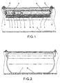
- FIG. 1 the pipe shutter produced using a flexible waterproof structure inflatable by a pyrotechnic gas generator is awaiting operation.
- the flexible shutter (2) is placed in a pipe (1); it is folded (3) around the gas generator system (4).
- the assembly is preferably fixed to the pipe (1) using two fasteners (11).
- the gas generator system (4) consists of a diffuser tube (15) in which a generator is placed gas (5) and an igniter plug (6) which contains the firing signal receiver (7), source energy (8), the optical electrical connection (9) or mechanical to the igniter (10) of the gas generator (5).
- the generator system gas (4) can be located outside the airbag (2).
- the flexible shutter (2) which is inflatable and sealed and inflatable by a pyrotechnic gas generator is inflated and any flow is blocked in the pipe (1).
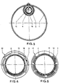
- Figure 3 shows a sectional view of the pipe (1) equipped with a bag (2) folded ready for use with a simple folding in two half-shells, around the gas generator (4) whose gases fill the bag (2) through the holes (16).
- FIGS 4 and 5 show other examples of possible folding without departing from the invention.
- the fabric of the bag is preferably made of fiber thermoplastic, such as polyester or polyamide, or fiberglass. In all cases, for its watertightness, it is coated with a preferential PVC film or elastomer.
- FIG. 6 presents one of the other construction possibilities, in the case where it is possible to use a manhole (18).
- a vertical housing contains the signal receiver ignition (7), the power source (8), the generator gas (5) and its ignition (10). Waiting for operation, the bag (2) is folded around the tube diffuser (15) containing the expansion chamber (14) and its calibrated input (13).
- the system is preferentially reusable. After opening a drain plug, we takes the system out of the pipeline by dismantling the fasteners (11). We remove the plug (6) and then generator (5). We put back a new generator (5), we close the cap (6), fold the bag (2) and place in a holding sleeve (17), the system in the pipeline (1) using fasteners (11).
- the shutter inflatable pipe by gas generator pyrotechnic may not be introduced into the pipeline that at the time of the intervention and its swelling.
- the fire barrier deployable by inflation using a pyrotechnic gas generator is in the deployed position.
- This barrier (21) is in the form of a mattress consisting of two walls (22) of coated fabric which is waterproof on the inside and fireproof or thermally protected on the outside.
- a fabric made of fire-resistant fibers is used.
- the two walls (22) are regularly assembled in grooves (23), preferably by ultrasonic welding, high frequency or hot.
- the inflated barrier (21) has tubes stiffeners (24) which communicate with the generator system gas (26) through a filter diffuser (27).
- the barrier (21) While waiting for operation, the barrier (21) is folded back in the housing (25) closed by a sealing film (28).
- the gas generator system (26) of the barrier deployable anti-fire by pyrotechnic gas generator is preferably of similar construction to that of the inflatable waterproof flexible shutter by generator pyrotechnic gas (4).
- the deployment of the fire barrier (s) is initiated either manually or automatically by a sensor.
- the initiator turns on the powder charge to the system gas generator (6).
- the gases generated by combustion of this powder in the chamber are directed, through the diffuser filter (27) towards the inflatable structure (22) of the barrier (21).
- the barrier (21) under the effect of pressure, begins to push the storage membrane (28) which tears, allowing deployment of the mattress (22) and the inflation of the network of tubes (24) which ensures the rigidity of the barrier without preventing the passage of personnel wishing to evacuate the premises.
- Figures 8 and 9 show the inflatable jack by pyrotechnic gas generator in the "inflated" position. It preferably consists of a tubular fabric structure (30) coated for sealing, the lower part of which is reinforced with the aid of a base (34) made of elastomer or thermoplastic.
- the upper part is closed by a cover (32) made of elastomer or thermoplastic, equipped with the system gas generator (39), the drain plug (37) and the positioning tab (33) on the chassis vehicle.
- the drain plug (37) is fitted with a security (38).
- the gas generator system (39) contains the gas generator (35) and its ignition system percussion or electric (36).
- the tubular structure (30) can be lined with a tubular structure interior (31) fitted with a non-return inflation valve (40) ensuring safety in the event of deflation accident of the basic tubular structure (30).
- FIG. 10 shows a variant form of the flexible structure of the inflatable jack by pyrotechnic gas generator. It is produced by welded assembly of two flat flanges (41), the flat geometry of which is circular or square.
- the inflatable jack is first positioned under the vehicle; the sole (34) must face the ground.
- the tab (33) is inserted into the housing provided for this purpose under the vehicle body.
- the initiation system is manually operated (36) to fire the gas generator (35).
- the jack is deployed (3 to 5 seconds approximately) and the vehicle lifts allowing operator intervention (removing the wheel punctured and reassembly of the spare wheel; insertion of a de-bogging system ).
- the invention allows the realization of many other inflatable equipment using a gas generator pyrotechnic which we cannot describe as example.
Landscapes
- Engineering & Computer Science (AREA)
- General Engineering & Computer Science (AREA)
- Mechanical Engineering (AREA)
- Air Bags (AREA)
- Materials For Medical Uses (AREA)
- Prostheses (AREA)
- Tents Or Canopies (AREA)
- Buildings Adapted To Withstand Abnormal External Influences (AREA)
- Feeding, Discharge, Calcimining, Fusing, And Gas-Generation Devices (AREA)
- Agricultural Chemicals And Associated Chemicals (AREA)
- Packages (AREA)
- Acyclic And Carbocyclic Compounds In Medicinal Compositions (AREA)
- Devices For Medical Bathing And Washing (AREA)
- Vehicle Cleaning, Maintenance, Repair, Refitting, And Outriggers (AREA)
- Pipe Accessories (AREA)
- Treatments For Attaching Organic Compounds To Fibrous Goods (AREA)
- Woven Fabrics (AREA)
Claims (8)
- Ausrüstung mit einer weichen, dichten aufblasbaren Struktur (2), dadurch gekennzeichnet, daß sie einen pyrotechnischen Gaserzeuger (4) aufweist, der das Aufblasen dieser weichen Struktur ermöglicht.
- Ausrüstung nach Anspruch 1, dadurch gekennzeichnet, daß die weiche Struktur (2) ein Gewebe aus Polyamid-, Polyester- Aramid- oder Glasfasern mit einem Überzug aus PVC, Silikon oder einem synthetischen oder natürlichen Elastomer ist.
- Ausrüstung nach Anspruch 1, dadurch gekennzeichnet, daß die pyrotechnischen Gaserzeuger Gaserzeugungsraten haben, die durch Formentwicklungen von Treibblöcken oder programmierte aufeinanderfolgende Zündungen von Mikrogeneratoren einstellbar sind.
- Ausrüstung nach einem der Ansprüche 1 bis 3, dadurch gekennzeichnet, daß die Struktur einen weichen, aufblasbaren Leitungsverschluß (2) bildet, der um den Diffusor (15) gefaltet ist, der den pyrotechnischen Gaserzeuger (4) bildet.
- Ausrüstung nach Anspruch 4, dadurch gekennzeichnet, daß das Zündsignal für den pyrotechnischen Gaserzeuger (4) von einem automatischen Schadstoffdetektor oder einer Fernsteuerung geliefert wird.
- Ausrüstung nach einem der Ansprüche 1 bis 3, dadurch gekennzeichnet, daß die weiche aufblasbare Struktur (21) eine entfaltbare Brandschutzbarriere bildet, die aus einem Gewebe aus feuerhemmenden Fasern, einem flammenhemmenden Gewebe oder einem wärmegeschützten Gewebe hergestellt ist.
- Ausrüstung nach einem der Ansprüche 1 bis 3, dadurch gekennzeichnet, daß die weiche aufblasbare Struktur (30) einen aufblasbaren Wagenheber bildet, der in seinem oberen Bereich eine Einrichtung (33) zur Verbindung mit oder Abstützung an dem Fahrzeugaufbau, einen Auslöser (36) für einen Perkussionszünder des Gaserzeugers und einen Entleerungsstöpsel (37) mit einem Sicherheitsventil (38) aufweist.
- Ausrüstung nach einem der Ansprüche 1 bis 3, dadurch gekennzeichnet, daß die weiche Struktur einen aufblasbaren Stellantrieb, einen aufblasbaren Verschluß, eine aufblasbare Barriere, eine aufblasbare Sicherheitsplanke bildet, aufgeblasen von wiederaufladbaren Gaserzeugern mit autonomer, elektrischer oder Perkussionszündung.
Applications Claiming Priority (3)
| Application Number | Priority Date | Filing Date | Title |
|---|---|---|---|
| FR9707457A FR2764672B1 (fr) | 1997-06-13 | 1997-06-13 | Structures souples etanches gonflables par generateurs de gaz pyrotechniques |
| FR9707457 | 1997-06-13 | ||
| PCT/FR1998/001233 WO1998057093A1 (fr) | 1997-06-13 | 1998-06-12 | Structures souples gonflables |
Publications (2)
| Publication Number | Publication Date |
|---|---|
| EP0988489A1 EP0988489A1 (de) | 2000-03-29 |
| EP0988489B1 true EP0988489B1 (de) | 2001-11-28 |
Family
ID=9508035
Family Applications (1)
| Application Number | Title | Priority Date | Filing Date |
|---|---|---|---|
| EP98930848A Expired - Lifetime EP0988489B1 (de) | 1997-06-13 | 1998-06-12 | Flexible, aufblasbare strukturen |
Country Status (12)
| Country | Link |
|---|---|
| EP (1) | EP0988489B1 (de) |
| JP (1) | JP2002506412A (de) |
| AT (1) | ATE209765T1 (de) |
| AU (1) | AU8114098A (de) |
| CA (1) | CA2294827A1 (de) |
| DE (1) | DE69802684T2 (de) |
| DK (1) | DK0988489T3 (de) |
| ES (1) | ES2168770T3 (de) |
| FR (1) | FR2764672B1 (de) |
| NO (1) | NO996096L (de) |
| PT (1) | PT988489E (de) |
| WO (1) | WO1998057093A1 (de) |
Families Citing this family (13)
| Publication number | Priority date | Publication date | Assignee | Title |
|---|---|---|---|---|
| FR2821413A1 (fr) | 2001-02-28 | 2002-08-30 | Alain Denes | Dispositif depliable et son procede de deploiement |
| EP1503827B1 (de) | 2002-05-15 | 2006-05-24 | Prospective Concepts AG | Schott zur abdichtung eines tunnels im brandfall |
| DE10230767A1 (de) * | 2002-07-09 | 2004-01-22 | Zf Friedrichshafen Ag | Sicherheitssystem für Rohre und Kanäle |
| DE10236726A1 (de) * | 2002-08-02 | 2004-02-19 | Becker, Heike | System zum Verschluss von Öffnungen, Durchlässen |
| WO2004053378A1 (es) * | 2002-12-09 | 2004-06-24 | Matrival, S.L. | Dispositivo para obturar conductos de conducción de líneas eléctricas, telefónicas y similares |
| DE102007062602A1 (de) * | 2007-12-22 | 2009-06-25 | Diehl Bgt Defence Gmbh & Co. Kg | Hebezeug zum Anheben einer Last, insbesondere als Bestandteil einer Notausrüstung für Bergungszwecke |
| EP3000964A1 (de) * | 2014-09-27 | 2016-03-30 | INCD INSEMEX Petrosani | Ultraschnelle Bergwerks-Streckenabschottvorrichtung |
| BE1022921B1 (fr) | 2015-04-01 | 2016-10-19 | Techspace Aero S.A. | Banc d'essais de turboreacteur d'aeronef avec obturateurs |
| JP2017057996A (ja) * | 2015-09-18 | 2017-03-23 | クロダイト工業株式会社 | 遮断装置用エアバッグ |
| FR3060652B1 (fr) * | 2016-12-21 | 2019-08-23 | Arianegroup Sas | Nacelle pour turboreacteur d’aeronef equipee d’un dispositif d’extinction de feu |
| CN107998533A (zh) * | 2017-11-16 | 2018-05-08 | 广东工业大学 | 一种充气式隧道防火隔离装置 |
| FR3088983B1 (fr) * | 2018-11-23 | 2020-12-11 | Commissariat Energie Atomique | Registre aéraulique adoptant un état intermédiaire filtrant entre des états passant et non-passant |
| JP2020133651A (ja) * | 2019-02-13 | 2020-08-31 | 株式会社ホーシン | 止水プラグ |
Family Cites Families (4)
| Publication number | Priority date | Publication date | Assignee | Title |
|---|---|---|---|---|
| US2598207A (en) * | 1946-06-14 | 1952-05-27 | Bailey Meter Co | Valving apparatus |
| US3459230A (en) * | 1966-08-31 | 1969-08-05 | Lester R Smith | Pipe stopper |
| OA07128A (fr) * | 1981-06-23 | 1984-03-31 | Petroles Cie Francaise | Obturation interne pour conduite. |
| FR2748543B1 (fr) * | 1996-05-10 | 1998-07-03 | Musthane | Dispositif gonflable pour l'obturation d'une conduite et installation comprenant un tel dispositif |
-
1997
- 1997-06-13 FR FR9707457A patent/FR2764672B1/fr not_active Expired - Fee Related
-
1998
- 1998-06-12 AU AU81140/98A patent/AU8114098A/en not_active Abandoned
- 1998-06-12 ES ES98930848T patent/ES2168770T3/es not_active Expired - Lifetime
- 1998-06-12 EP EP98930848A patent/EP0988489B1/de not_active Expired - Lifetime
- 1998-06-12 DE DE69802684T patent/DE69802684T2/de not_active Expired - Fee Related
- 1998-06-12 CA CA002294827A patent/CA2294827A1/en not_active Abandoned
- 1998-06-12 WO PCT/FR1998/001233 patent/WO1998057093A1/fr not_active Ceased
- 1998-06-12 DK DK98930848T patent/DK0988489T3/da active
- 1998-06-12 PT PT98930848T patent/PT988489E/pt unknown
- 1998-06-12 JP JP50179899A patent/JP2002506412A/ja active Pending
- 1998-06-12 AT AT98930848T patent/ATE209765T1/de not_active IP Right Cessation
-
1999
- 1999-12-09 NO NO996096A patent/NO996096L/no not_active Application Discontinuation
Also Published As
| Publication number | Publication date |
|---|---|
| DK0988489T3 (da) | 2002-03-25 |
| ATE209765T1 (de) | 2001-12-15 |
| NO996096L (no) | 2000-02-01 |
| WO1998057093A1 (fr) | 1998-12-17 |
| DE69802684D1 (de) | 2002-01-10 |
| NO996096D0 (no) | 1999-12-09 |
| EP0988489A1 (de) | 2000-03-29 |
| CA2294827A1 (en) | 1998-12-17 |
| FR2764672A1 (fr) | 1998-12-18 |
| ES2168770T3 (es) | 2002-06-16 |
| FR2764672B1 (fr) | 2001-02-09 |
| DE69802684T2 (de) | 2002-08-22 |
| JP2002506412A (ja) | 2002-02-26 |
| AU8114098A (en) | 1998-12-30 |
| PT988489E (pt) | 2002-05-31 |
Similar Documents
| Publication | Publication Date | Title |
|---|---|---|
| FR2764672A1 (fr) | Structures souples etanches gonflables par generateurs de gaz pyrotechniques | |
| KR102409287B1 (ko) | 튜브형 차량화재진화장치 | |
| CA2703853C (fr) | Dispositif d'ejection d'un fluide a etancheite renforcee | |
| CA2275767C (en) | A deployable diverging part for a thruster | |
| FR2621944A1 (fr) | Voute gonflable a double paroi polylobee | |
| KR102626312B1 (ko) | 튜브형 차량화재진화장치 | |
| EP2635836B1 (de) | Vorrichtung zur selbstverbindung an mindestens einer rohrleitung | |
| US20120198987A1 (en) | Purging an airlock of an explosion containment chamber | |
| KR101755426B1 (ko) | 박형 에어 잭 | |
| EP1054370B1 (de) | Vorrichtung zum Schutz eines Gebietes gegen Eindringen | |
| NZ536269A (en) | Blocking assembly with inflatable bladder typically for blocking drains and cesspits in event of chemical spills | |
| US7500489B2 (en) | Contained pipeline system with brine filled interstitial space and method for detecting leakage in same | |
| EP4065926B1 (de) | Mobile vorrichtung zur neutralisierung einer chemischen oder biologischen waffe | |
| US6705242B2 (en) | Method and apparatus for hermetically sealing openings of an explosion containment chamber | |
| EP0828910B1 (de) | Zusammen- und aus-ziehbares,aufblasbares gewölbe | |
| FR2735085A1 (fr) | Systeme de tuyauterie pour le remplissage en carburant liquide d'une cuve enterree et pour le transfert de ce carburant vers un poste de distribution | |
| KR20170068548A (ko) | 고압 소화기 | |
| FR2597918A1 (fr) | Porte gonflable etanche et constructions la comprenant | |
| FR2822174A1 (fr) | Cloison deployable utilisable dans les tunnels de circulation routiere | |
| FR2821054A1 (fr) | Systeme de renflouage de bateau coule et similaire | |
| FR2945453A1 (fr) | Dispositif d'ejection d'un fluide. | |
| CN121846569A (zh) | 一种充气式防火罩 | |
| CN121229181A (zh) | 一种用于坑道爆炸冲击波的一体式充气防护装置 | |
| FR2677700A1 (fr) | Methode et dispositif de captage d'un puits en eruption, le dispositif etant fixe par explosion. | |
| CN121408022A (zh) | 一种泄压缓冲式坑道爆炸冲击防护气囊 |
Legal Events
| Date | Code | Title | Description |
|---|---|---|---|
| PUAI | Public reference made under article 153(3) epc to a published international application that has entered the european phase |
Free format text: ORIGINAL CODE: 0009012 |
|
| 17P | Request for examination filed |
Effective date: 20000113 |
|
| AK | Designated contracting states |
Kind code of ref document: A1 Designated state(s): AT BE CH DE DK ES FR GB GR IT LI LU NL PT SE |
|
| 17Q | First examination report despatched |
Effective date: 20000707 |
|
| GRAG | Despatch of communication of intention to grant |
Free format text: ORIGINAL CODE: EPIDOS AGRA |
|
| RAP1 | Party data changed (applicant data changed or rights of an application transferred) |
Owner name: COMPYTEC TECHNOLOGIES |
|
| GRAG | Despatch of communication of intention to grant |
Free format text: ORIGINAL CODE: EPIDOS AGRA |
|
| GRAG | Despatch of communication of intention to grant |
Free format text: ORIGINAL CODE: EPIDOS AGRA |
|
| GRAG | Despatch of communication of intention to grant |
Free format text: ORIGINAL CODE: EPIDOS AGRA |
|
| GRAH | Despatch of communication of intention to grant a patent |
Free format text: ORIGINAL CODE: EPIDOS IGRA |
|
| RAP1 | Party data changed (applicant data changed or rights of an application transferred) |
Owner name: S.E.I.B. S.A.R.L. |
|
| GRAH | Despatch of communication of intention to grant a patent |
Free format text: ORIGINAL CODE: EPIDOS IGRA |
|
| GRAA | (expected) grant |
Free format text: ORIGINAL CODE: 0009210 |
|
| RIN1 | Information on inventor provided before grant (corrected) |
Inventor name: BOYAULT, JEAN-PIERRE Inventor name: CASTAGNER, BERNARD |
|
| AK | Designated contracting states |
Kind code of ref document: B1 Designated state(s): AT BE CH DE DK ES FR GB GR IT LI LU NL PT SE |
|
| REF | Corresponds to: |
Ref document number: 209765 Country of ref document: AT Date of ref document: 20011215 Kind code of ref document: T |
|
| REG | Reference to a national code |
Ref country code: CH Ref legal event code: EP |
|
| REG | Reference to a national code |
Ref country code: GB Ref legal event code: IF02 |
|
| REF | Corresponds to: |
Ref document number: 69802684 Country of ref document: DE Date of ref document: 20020110 |
|
| GBT | Gb: translation of ep patent filed (gb section 77(6)(a)/1977) |
Effective date: 20020131 |
|
| REG | Reference to a national code |
Ref country code: DK Ref legal event code: T3 |
|
| REG | Reference to a national code |
Ref country code: CH Ref legal event code: NV Representative=s name: PATMED AG |
|
| REG | Reference to a national code |
Ref country code: PT Ref legal event code: SC4A Free format text: AVAILABILITY OF NATIONAL TRANSLATION Effective date: 20020227 |
|
| PG25 | Lapsed in a contracting state [announced via postgrant information from national office to epo] |
Ref country code: LU Free format text: LAPSE BECAUSE OF NON-PAYMENT OF DUE FEES Effective date: 20020612 Ref country code: GB Free format text: LAPSE BECAUSE OF NON-PAYMENT OF DUE FEES Effective date: 20020612 Ref country code: AT Free format text: LAPSE BECAUSE OF NON-PAYMENT OF DUE FEES Effective date: 20020612 |
|
| PG25 | Lapsed in a contracting state [announced via postgrant information from national office to epo] |
Ref country code: SE Free format text: LAPSE BECAUSE OF NON-PAYMENT OF DUE FEES Effective date: 20020613 Ref country code: ES Free format text: LAPSE BECAUSE OF NON-PAYMENT OF DUE FEES Effective date: 20020613 |
|
| REG | Reference to a national code |
Ref country code: ES Ref legal event code: FG2A Ref document number: 2168770 Country of ref document: ES Kind code of ref document: T3 |
|
| PG25 | Lapsed in a contracting state [announced via postgrant information from national office to epo] |
Ref country code: LI Free format text: LAPSE BECAUSE OF NON-PAYMENT OF DUE FEES Effective date: 20020630 Ref country code: CH Free format text: LAPSE BECAUSE OF NON-PAYMENT OF DUE FEES Effective date: 20020630 Ref country code: BE Free format text: LAPSE BECAUSE OF NON-PAYMENT OF DUE FEES Effective date: 20020630 |
|
| PGFP | Annual fee paid to national office [announced via postgrant information from national office to epo] |
Ref country code: DE Payment date: 20020630 Year of fee payment: 5 |
|
| PG25 | Lapsed in a contracting state [announced via postgrant information from national office to epo] |
Ref country code: DK Free format text: LAPSE BECAUSE OF NON-PAYMENT OF DUE FEES Effective date: 20020731 |
|
| REG | Reference to a national code |
Ref country code: GR Ref legal event code: EP Ref document number: 20020400657 Country of ref document: GR |
|
| PLBE | No opposition filed within time limit |
Free format text: ORIGINAL CODE: 0009261 |
|
| STAA | Information on the status of an ep patent application or granted ep patent |
Free format text: STATUS: NO OPPOSITION FILED WITHIN TIME LIMIT |
|
| 26N | No opposition filed | ||
| BERE | Be: lapsed |
Owner name: *SEIB S.A.R.L. Effective date: 20020630 |
|
| PG25 | Lapsed in a contracting state [announced via postgrant information from national office to epo] |
Ref country code: NL Free format text: LAPSE BECAUSE OF NON-PAYMENT OF DUE FEES Effective date: 20030101 |
|
| PG25 | Lapsed in a contracting state [announced via postgrant information from national office to epo] |
Ref country code: GR Free format text: LAPSE BECAUSE OF NON-PAYMENT OF DUE FEES Effective date: 20030108 |
|
| GBPC | Gb: european patent ceased through non-payment of renewal fee |
Effective date: 20020612 |
|
| EUG | Se: european patent has lapsed | ||
| REG | Reference to a national code |
Ref country code: CH Ref legal event code: PL |
|
| REG | Reference to a national code |
Ref country code: DK Ref legal event code: EBP |
|
| PG25 | Lapsed in a contracting state [announced via postgrant information from national office to epo] |
Ref country code: FR Free format text: LAPSE BECAUSE OF NON-PAYMENT OF DUE FEES Effective date: 20030228 |
|
| NLV4 | Nl: lapsed or anulled due to non-payment of the annual fee |
Effective date: 20030101 |
|
| REG | Reference to a national code |
Ref country code: FR Ref legal event code: ST |
|
| PG25 | Lapsed in a contracting state [announced via postgrant information from national office to epo] |
Ref country code: PT Free format text: LAPSE BECAUSE OF NON-PAYMENT OF DUE FEES Effective date: 20031231 |
|
| PG25 | Lapsed in a contracting state [announced via postgrant information from national office to epo] |
Ref country code: DE Free format text: LAPSE BECAUSE OF NON-PAYMENT OF DUE FEES Effective date: 20040101 |
|
| REG | Reference to a national code |
Ref country code: PT Ref legal event code: MM4A Free format text: LAPSE DUE TO NON-PAYMENT OF FEES Effective date: 20031231 |
|
| REG | Reference to a national code |
Ref country code: ES Ref legal event code: FD2A Effective date: 20030711 |
|
| PG25 | Lapsed in a contracting state [announced via postgrant information from national office to epo] |
Ref country code: IT Free format text: LAPSE BECAUSE OF NON-PAYMENT OF DUE FEES Effective date: 20050612 |
|
| PG25 | Lapsed in a contracting state [announced via postgrant information from national office to epo] |
Ref country code: PT Free format text: LAPSE BECAUSE OF NON-PAYMENT OF DUE FEES Effective date: 20020612 |