EP0988117B1 - Sheet coating machine - Google Patents
Sheet coating machine Download PDFInfo
- Publication number
- EP0988117B1 EP0988117B1 EP98928429A EP98928429A EP0988117B1 EP 0988117 B1 EP0988117 B1 EP 0988117B1 EP 98928429 A EP98928429 A EP 98928429A EP 98928429 A EP98928429 A EP 98928429A EP 0988117 B1 EP0988117 B1 EP 0988117B1
- Authority
- EP
- European Patent Office
- Prior art keywords
- sheet
- station
- coating
- vapours
- machine according
- Prior art date
- Legal status (The legal status is an assumption and is not a legal conclusion. Google has not performed a legal analysis and makes no representation as to the accuracy of the status listed.)
- Expired - Lifetime
Links
Images




Classifications
-
- B—PERFORMING OPERATIONS; TRANSPORTING
- B05—SPRAYING OR ATOMISING IN GENERAL; APPLYING FLUENT MATERIALS TO SURFACES, IN GENERAL
- B05C—APPARATUS FOR APPLYING FLUENT MATERIALS TO SURFACES, IN GENERAL
- B05C15/00—Enclosures for apparatus; Booths
-
- B—PERFORMING OPERATIONS; TRANSPORTING
- B05—SPRAYING OR ATOMISING IN GENERAL; APPLYING FLUENT MATERIALS TO SURFACES, IN GENERAL
- B05C—APPARATUS FOR APPLYING FLUENT MATERIALS TO SURFACES, IN GENERAL
- B05C9/00—Apparatus or plant for applying liquid or other fluent material to surfaces by means not covered by any preceding group, or in which the means of applying the liquid or other fluent material is not important
- B05C9/08—Apparatus or plant for applying liquid or other fluent material to surfaces by means not covered by any preceding group, or in which the means of applying the liquid or other fluent material is not important for applying liquid or other fluent material and performing an auxiliary operation
- B05C9/14—Apparatus or plant for applying liquid or other fluent material to surfaces by means not covered by any preceding group, or in which the means of applying the liquid or other fluent material is not important for applying liquid or other fluent material and performing an auxiliary operation the auxiliary operation involving heating or cooling
Definitions
- This invention relates to sheet coating machines, that is to say to machines for coating sheets with a variety of substances most of which include high quantities of volatile organic solvents which are evaporated off and incinerated during a following curing process in a thermal drying oven.
- solvent vapourise at the machine, and health and safety regulations require that these are not dissipated into the atmosphere but are incinerated.
- the object of the present invention is to avoid all of the disadvantages hereinbefore referred to.
- the invention comprises a sheet coating machine in which sheets are fed along a bed through a working area where they are given a coating of a volatile substance to an adjoining oven where the coating is cured, at least one cover which is moveable to provide access when necessary to the working area and which enables vapours produced by evaporation from the substance to be contained within the working area, air inlet means which enable the vapours to be extracted for incineration, and suction means which are arranged to extract the vapours downwardly from within the working area.
- the working area preferably comprises a coating station having a moveable cover which provides access when necessary to the coating station.
- the air inlet means of the coating station comprise vents in the moveable cover.
- the coating station is provided with a base, walls along its sides, and upstream and downstream baffle plates across its ends in order to contain the vapours within the coating station, the baffle plates being adapted to permit feeding of the sheets along the bed.
- the working area comprises also a sheet reject station disposed between the coating station and the oven and having another moveable cover which provides access when necessary to the sheet reject station.
- the sheet reject station is provided with a floor, walls along its sides, and upstream and downstream baffle plates across its ends in order to contain the vapours within the sheet reject station, the baffle plates being adapted to permit feeding of the sheets along the bed.
- the walls of the sheet reject station are continuations of the walls of the coating station, and the upstream baffle plate of the sheet reject station and the downstream baffle plate of the coating station are one and the same element.
- the air inlet means of the sheet reject station comprise vents in a reject sheet withdrawal door in one of the walls.
- the suction means which are arranged to extract the vapours downwardly comprise ducts connected to the base of the coating station, to the sheet reject station, to a gearbox for driving the machine, and to a housing for a replaceable tank from which the substance is supplied to the coating station.
- the ducts communicate with a common duct in the base of the machine leading to an upper zone of the oven.
- the sheet coating machine is preferably provided with a hoist for enabling machine elements to be changed which is disposed above the working area and is completely unimpeded by the suction means which are arranged to extract the vapours downwardly.
- a sheet coating machine, an adjoining sheet supplying mechanism therefor and an adjoining thermal drying oven therefor are indicated generally at 10, 12 and 14 respectively.
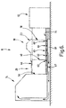
- the machine 10 has a flat bed 16 along which sheets are fed by conveyor means 17 and 19 through a working area comprising a coating station indicated generally at 18 where they are given a coating of a volatile substance such as lacquer and, downstream of the coating station 18, a sheet reject station indicated generally at 20 which allows a sheet to be withdrawn from the bed 16 for inspection. From the sheet reject station 20 the sheets normally pass to the oven 14 where the coating is cured.
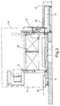
- the coating station 18 has a humped cover 23 which is pivotally raiseable about an axis 21 through about 90 degrees to the position shown in broken lines at 22 in Figure 1 by means of a hydraulic cylinder 24 (see Figure 4) which is power-operated with push-button control and is aided by a counterweight 26, to provide unrestricted access when necessary to said station.
- the cover 23 rests on the bed 16 when in its lowered operational position illustrated in full lines in Figure 1 so as to enable vapours produced by evaporation from the substance to be contained within the coating station 18, and is provided with glass inspection panels 28, areas of air inlet vents 30, and further air inlet vents (not shown) in a small access door 32.
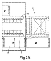
- the coating station 18 has a base which is part of a continuous base 34 for the whole machine 10, walls 36 along its sides, and respective upstream and downstream baffle plates 38 and 40 across its ends in order to contain the vapours within said station.
- the upper ends of the baffle plates 38 and 40 terminate just below the bed 16 to form a shallow slot permitting feeding of the sheets therealong.
- the coating station 18 includes a housing 42 for a replaceable tank 44 from which the substance is supplied to said station. Doors 45 are provided in the walls 36 to allow access to the coating station 18 when the cover 23 is raised in order to facilitate work on the machine by an operator.
- the sheet reject station 20 has a flat cover 46 which is pivotally raiseable about an axis 47 to the position shown in broken lines at 48 in Figure 1, to provide access when necessary to said station, by means which are similar to those for raising the cover 23 but which are not shown because they are disposed on the other side of the machine 10.
- the cover 46 rests on the bed 16 when in its lowered operational position illustrated in full lines in Figure 1 so as to enable vapours produced by evaporation from the substance to be contained within the sheet rejection station 20, and is provided with a glass inspection panel 50.
- the sheet reject station 20 has a floor 52 disposed above the base 34, walls 54 along its sides which are continuations of the walls 36 of the coating station 18, an upstream baffle plate across one end constituted by the downstream baffle plate 40 of the station 18, and a downstream baffle plate 56 across the other end in order to contain the vapours within the station 20.
- the upper end of the baffle plate 56 terminates just below the bed 16 to form a shallow slot permitting feeding of the sheets therealong.
- Air inlet vents (not shown) are provided in a reject sheet withdrawal door 58 in one of the walls 54.
- suction means which are arranged to extract the vapours downwardly from within the working area 18, 20 include a duct 60 connected to the front zone of the base of the coating station 18, a duct 62 connected to the rear zone of the base of said station, said zones being delineated by boundary walls 64, a duct 66 connected to the housing 42 for the tank 44, a duct 63 connected to the sheet reject station 20, and a duct 65 connected to a gearbox 71 for driving the machine 10.
- the suction means also include a suction fan 67 housed alongside the machine 10 which extracts all the vapours from the working area 18, 20 of the machine 10 downwardly through the aforesaid ducts into the base of the machine whence they pass through a common duct 69 into an upper zone of the oven 14 where they are incinerated.
- the suction fan is sufficiently powerful to maintain a slight negative gauge pressure within the working area 18, 20, which effectively draws in fresh air through the inlet vents hereinbefore referred to.
- concentration of vapours within the working area 18, 20 can be high because the operator is not exposed thereto, the requisite extraction flow rate is relatively low thus providing high oven thermal efficiency and low running costs.
- the machine 10 has front and rear platforms 68 and a hand-rail 70 for the use of the operator, and is provided with a hoist 72 with a jib 74 for enabling machine elements to be changed.
- Said hoist is disposed above the working area 18, 20 and is completely unimpeded by the suction means which are arranged to extract the vapours downwardly aided by the fact that said vapours are heavier than air.
- the working area of the machine comprises simply a coating station, no sheet reject station being provided.
Landscapes
- Coating Apparatus (AREA)
- Details Or Accessories Of Spraying Plant Or Apparatus (AREA)
Description
Claims (11)
- A sheet coating machine (10) in which sheets are fed along a bed through a working area (18, 20) where they are given a coating of a volatile substance to an adjoining oven (14) where the coating is cured, comprising at least one cover (23) which is moveable to provide access when necessary to the working area and which enables vapours produced by evaporation from the substance to be contained within the working area, air inlet means (30, 32) which enable the vapours to be extracted for incineration, and suction means (60 to 67) which are arranged to extract the vapours downwardly from within the working area.
- A sheet coating machine according to claim 1, wherein the working area comprises a coating station (18) having a moveable cover which provides access when necessary to the coating station.
- A sheet coating machine according to claim 2, wherein the air inlet means (30) of the coating station (18) comprise vents in the moveable cover.
- A sheet coating machine according to claim 2 or claim 3, wherein the coating station (18) is provided with a base (34), walls (36) along its sides, and upstream and downstream baffle plates (38, 40) across its ends in order to contain the vapours within the coating station, the baffle plates being adapted to permit feeding of the sheets along the bed.
- A sheet coating machine according to any one of claims 2 to 4, wherein the working area (18, 20) comprises also a sheet reject stations (20) disposed between the coating station (18) and the oven (14) and having another moveable cover (46) which provides access when necessary to the sheet reject station.
- A sheet coating machine according to claim 5, wherein the sheet reject station (20) is provided with a floor (52), walls (54) along its sides, and upstream and downstream baffle plates (40, 56) across its ends in order to contain the vapours within the sheet reject station (20), the baffle plates being adapted to permit feeding of the sheets along the bed.
- A sheet coating machine according to claim 6, wherein the walls (54) of the sheet reject station (20) are continuations of the walls (36) of the coating station (18), and the upstream baffle plate of the sheet reject station and the downstream baffle plate of the coating station are one and the same element (40).
- A sheet coating machine according to claim 6 or claim 7, wherein the air inlet means of the sheet reject station comprise vents in a reject sheet withdrawal door (58) in one of the walls.
- A sheet coating machine according to claims 1 to 6, wherein the suction means (60 to 67) which are arranged to extract the vapours downwardly comprise ducts connected to the base of the coating station, to the sheet reject station to a gearbox (71) for driving the machine, and to a housing (42) for a replaceable tank (44) from which the substance is supplied to the coating station.
- A sheet coating machine according to claim 9, wherein the ducts communicate with a common duct (69) in the base of the machine leading to an upper zone of the oven.
- A sheet coating machine according to any one of the preceding claims, provided with a hoist (72) for enabling machine elements to be changed which is disposed above the working area (18, 20) and is completely unimpeded by the suction means which are arranged to extract the vapours downwardly.
Applications Claiming Priority (3)
| Application Number | Priority Date | Filing Date | Title |
|---|---|---|---|
| GBGB9712709.6A GB9712709D0 (en) | 1997-06-18 | 1997-06-18 | Sheet coating machine |
| GB9712709 | 1997-06-18 | ||
| PCT/GB1998/001608 WO1998057758A1 (en) | 1997-06-18 | 1998-06-16 | Sheet coating machine |
Publications (2)
| Publication Number | Publication Date |
|---|---|
| EP0988117A1 EP0988117A1 (en) | 2000-03-29 |
| EP0988117B1 true EP0988117B1 (en) | 2003-09-17 |
Family
ID=10814418
Family Applications (1)
| Application Number | Title | Priority Date | Filing Date |
|---|---|---|---|
| EP98928429A Expired - Lifetime EP0988117B1 (en) | 1997-06-18 | 1998-06-16 | Sheet coating machine |
Country Status (7)
| Country | Link |
|---|---|
| US (1) | US6419744B1 (en) |
| EP (1) | EP0988117B1 (en) |
| JP (1) | JP2002505616A (en) |
| AU (1) | AU8026198A (en) |
| DE (1) | DE69818258D1 (en) |
| GB (2) | GB9712709D0 (en) |
| WO (1) | WO1998057758A1 (en) |
Families Citing this family (2)
| Publication number | Priority date | Publication date | Assignee | Title |
|---|---|---|---|---|
| JP3476437B2 (en) * | 2001-01-05 | 2003-12-10 | 株式会社日本アルミボデーメンテナンス | Booth for film painting |
| KR101509864B1 (en) * | 2012-11-07 | 2015-04-06 | (주)엘지하우시스 | Apparatus for cleaning powder |
Family Cites Families (10)
| Publication number | Priority date | Publication date | Assignee | Title |
|---|---|---|---|---|
| US4136636A (en) * | 1977-09-26 | 1979-01-30 | B & K Machinery International Ltd. | Solvent vapor collector |
| US4173924A (en) | 1978-03-01 | 1979-11-13 | Schweitzer Industrial Corporation | Paint spray booth with air supply system |
| US4266504A (en) | 1979-08-10 | 1981-05-12 | Deere & Company | Paint spraying assembly |
| US4600608A (en) * | 1981-10-17 | 1986-07-15 | Lucas Industries | Surface coating apparatus and method |
| JPS58195675U (en) * | 1982-06-17 | 1983-12-26 | トヨタ自動車株式会社 | painting booth |
| US4714010A (en) * | 1985-04-12 | 1987-12-22 | Cm & E/California, Inc. | Industrial exhaust ventilation system |
| US4865872A (en) * | 1987-02-17 | 1989-09-12 | Enamel Products & Plating Company | Strip inspecting apparatus and associated method |
| US4874412A (en) * | 1988-06-03 | 1989-10-17 | Richmond Bank | Paint spray booth and filter therefor |
| US5023116A (en) * | 1989-08-07 | 1991-06-11 | Larry Williams | Environmentally acceptable process and apparatus for ventilation of continuous paint lines |
| US5246501A (en) * | 1990-12-07 | 1993-09-21 | Alliedsignal Inc. | Flash drying treatment of solvent from workpieces |
-
1997
- 1997-06-18 GB GBGB9712709.6A patent/GB9712709D0/en active Pending
-
1998
- 1998-06-16 AU AU80261/98A patent/AU8026198A/en not_active Abandoned
- 1998-06-16 US US09/445,893 patent/US6419744B1/en not_active Expired - Fee Related
- 1998-06-16 EP EP98928429A patent/EP0988117B1/en not_active Expired - Lifetime
- 1998-06-16 DE DE69818258T patent/DE69818258D1/en not_active Expired - Lifetime
- 1998-06-16 JP JP50393199A patent/JP2002505616A/en active Pending
- 1998-06-16 WO PCT/GB1998/001608 patent/WO1998057758A1/en not_active Ceased
- 1998-06-18 GB GB9813080A patent/GB2326359B/en not_active Expired - Fee Related
Also Published As
| Publication number | Publication date |
|---|---|
| GB2326359B (en) | 2002-01-23 |
| AU8026198A (en) | 1999-01-04 |
| US6419744B1 (en) | 2002-07-16 |
| DE69818258D1 (en) | 2003-10-23 |
| JP2002505616A (en) | 2002-02-19 |
| EP0988117A1 (en) | 2000-03-29 |
| GB9712709D0 (en) | 1997-08-20 |
| WO1998057758A1 (en) | 1998-12-23 |
| GB2326359A (en) | 1998-12-23 |
| GB9813080D0 (en) | 1998-08-19 |
Similar Documents
| Publication | Publication Date | Title |
|---|---|---|
| EP1507925B1 (en) | Suction device and suction method for the disposal of dust in milling machines | |
| US5540152A (en) | Delivery conveyor with control window ventilation and extraction system | |
| US9126381B2 (en) | Box making machines | |
| JPH11334036A (en) | Sheet delivery device for sheet-fed printing press | |
| EP1790474A1 (en) | Sheet-fed or web-fed printing machine | |
| US5182869A (en) | Apparatus for cooling spent anodes of electrolytic melting baths | |
| GB2060161A (en) | Paint spraying process and apparatus | |
| CA2022391A1 (en) | Environmentally acceptable process and apparatus for ventilation of continuous paint lines | |
| US6419744B1 (en) | Sheet coating machine | |
| US5154010A (en) | Sheet drying apparatus | |
| CA1217334A (en) | Painting and evaporation cabin with air-return ventilation | |
| US5634401A (en) | Printing press powder removal system | |
| DE2736686C3 (en) | Device for electrochemical processing | |
| CN221165976U (en) | Automatic change material pumping and beating material isolator | |
| EP1066160B1 (en) | Offset printing method and an offset printing machine | |
| DE19501874C2 (en) | Sheet deposit system in printing machines with dryers | |
| WO1998054525A1 (en) | Device for exposing a substrate to uv rays and method for using this device | |
| DE3239868C2 (en) | Continuous dryer for essentially flat dry or printed material | |
| WO1990003855A1 (en) | A method and a system for local ventilation | |
| DE937106C (en) | Rotogravure printing machine for sheets | |
| DE19722957C2 (en) | Sheet delivery in printing machines | |
| CN117303298B (en) | Automatic change oil pumping and beat material isolating device | |
| BR112018067308B1 (en) | PAINT INSTALLATION FOR PAINTING A WORK PART AND METHOD FOR PAINTING A WORK PART | |
| DE10105518B4 (en) | suction | |
| DE3517116A1 (en) | Guard, in particular on printing machines |
Legal Events
| Date | Code | Title | Description |
|---|---|---|---|
| PUAI | Public reference made under article 153(3) epc to a published international application that has entered the european phase |
Free format text: ORIGINAL CODE: 0009012 |
|
| 17P | Request for examination filed |
Effective date: 19991203 |
|
| AK | Designated contracting states |
Kind code of ref document: A1 Designated state(s): BE DE DK ES FR IT NL |
|
| GRAG | Despatch of communication of intention to grant |
Free format text: ORIGINAL CODE: EPIDOS AGRA |
|
| 17Q | First examination report despatched |
Effective date: 20020306 |
|
| GRAG | Despatch of communication of intention to grant |
Free format text: ORIGINAL CODE: EPIDOS AGRA |
|
| GRAH | Despatch of communication of intention to grant a patent |
Free format text: ORIGINAL CODE: EPIDOS IGRA |
|
| GRAH | Despatch of communication of intention to grant a patent |
Free format text: ORIGINAL CODE: EPIDOS IGRA |
|
| GRAA | (expected) grant |
Free format text: ORIGINAL CODE: 0009210 |
|
| AK | Designated contracting states |
Kind code of ref document: B1 Designated state(s): BE DE DK ES FR IT NL |
|
| PG25 | Lapsed in a contracting state [announced via postgrant information from national office to epo] |
Ref country code: NL Free format text: LAPSE BECAUSE OF FAILURE TO SUBMIT A TRANSLATION OF THE DESCRIPTION OR TO PAY THE FEE WITHIN THE PRESCRIBED TIME-LIMIT Effective date: 20030917 Ref country code: IT Free format text: LAPSE BECAUSE OF FAILURE TO SUBMIT A TRANSLATION OF THE DESCRIPTION OR TO PAY THE FEE WITHIN THE PRESCRIBED TIME-LIMIT;WARNING: LAPSES OF ITALIAN PATENTS WITH EFFECTIVE DATE BEFORE 2007 MAY HAVE OCCURRED AT ANY TIME BEFORE 2007. THE CORRECT EFFECTIVE DATE MAY BE DIFFERENT FROM THE ONE RECORDED. Effective date: 20030917 Ref country code: FR Free format text: LAPSE BECAUSE OF FAILURE TO SUBMIT A TRANSLATION OF THE DESCRIPTION OR TO PAY THE FEE WITHIN THE PRESCRIBED TIME-LIMIT Effective date: 20030917 Ref country code: BE Free format text: LAPSE BECAUSE OF FAILURE TO SUBMIT A TRANSLATION OF THE DESCRIPTION OR TO PAY THE FEE WITHIN THE PRESCRIBED TIME-LIMIT Effective date: 20030917 |
|
| REF | Corresponds to: |
Ref document number: 69818258 Country of ref document: DE Date of ref document: 20031023 Kind code of ref document: P |
|
| PG25 | Lapsed in a contracting state [announced via postgrant information from national office to epo] |
Ref country code: DK Free format text: LAPSE BECAUSE OF FAILURE TO SUBMIT A TRANSLATION OF THE DESCRIPTION OR TO PAY THE FEE WITHIN THE PRESCRIBED TIME-LIMIT Effective date: 20031217 |
|
| PG25 | Lapsed in a contracting state [announced via postgrant information from national office to epo] |
Ref country code: DE Free format text: LAPSE BECAUSE OF FAILURE TO SUBMIT A TRANSLATION OF THE DESCRIPTION OR TO PAY THE FEE WITHIN THE PRESCRIBED TIME-LIMIT Effective date: 20031218 |
|
| PG25 | Lapsed in a contracting state [announced via postgrant information from national office to epo] |
Ref country code: ES Free format text: LAPSE BECAUSE OF FAILURE TO SUBMIT A TRANSLATION OF THE DESCRIPTION OR TO PAY THE FEE WITHIN THE PRESCRIBED TIME-LIMIT Effective date: 20031228 |
|
| NLV1 | Nl: lapsed or annulled due to failure to fulfill the requirements of art. 29p and 29m of the patents act | ||
| PLBE | No opposition filed within time limit |
Free format text: ORIGINAL CODE: 0009261 |
|
| STAA | Information on the status of an ep patent application or granted ep patent |
Free format text: STATUS: NO OPPOSITION FILED WITHIN TIME LIMIT |
|
| 26N | No opposition filed |
Effective date: 20040618 |
|
| EN | Fr: translation not filed |