BACKGROUND OF THE INVENTION
(1) Field of the Invention
-
The present invention generally relates
to a function-expansion device and electronic
equipment, and more particularly to a function-expansion
device and electronic equipment, the
function-expansion device being detachably connected
to the electronic equipment to provide extended
functions of the electronic equipment.
(2) Description of the Related Art
-
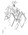
FIG. 1 shows a conventional electronic
equipment system. As shown in FIG. 1, the
conventional electronic equipment system 1 includes a
notebook PC (personal computer) 10 having a minimum
number of functions needed, and an expansion station
20. The expansion station 20 is attached to the
notebook PC 10 to expand the functions of the notebook
PC 10.
-
The notebook PC 10 has a connector 11
on the bottom of the notebook PC 10, and the expansion
station 20 has a connector 21 on the top of the
expansion station 20 at a position corresponding to a
position of the connector 11 on the notebook PC 10.
When the expansion station 20 is attached to the
notebook PC 10, the connector 11 and the connector 21
are connected to each other. In the expansion station
20, a floppy disk drive 22 and a CD-ROM drive 23 are
provided. The floppy disk drive 22 acts to read
information from or write information to a floppy disk
30. The CD-ROM drive 23 acts to read information from
a CD-ROM 40. The functions of the floppy disk drive
22 and the CD-ROM drive 23, which require a relatively
large amount of power consumption, are not provided on
the notebook PC 10, and these functions are provided
only when the expansion station 20 is attached to the
notebook PC 10.
-
However, in the conventional electronic
equipment system 1 of FIG. 1, the floppy disk drive 22
and the CD-ROM drive 23 are integrally provided on the
expansion station 20 in a fixed manner. Hence,
information recording media that can be used with the
notebook PC 10 are limited to the floppy disk and the
CD-ROM. Other recording media, such as magnetooptical
disks (MO), digital video disks (DVD) or high-capacity
floppy disks (LS-120), cannot be used with
the notebook PC 10. The range of expansion of the
functions provided by the expansion station 20 is
restricted, and the conventional electronic equipment
system 1 does not provide an adequate level of
operability, or ease of use, for the user.
-
Further, in the conventional electronic
equipment system 1, when the user intends to detach
the expansion station 20 from the notebook PC 10, it
is required to stop operation of the notebook PC 10 or
turn off a power switch of the notebook PC 10. The
conventional electronic equipment system 1 does not
provide an adequate level of operability, or ease of
use, for the user, even through the expansion station
20 provides extended functions of the notebook PC 10.
-
In addition, the conventional
electronic equipment system 1 including the expansion
station 20 is intended for the desktop use, and it is
not intended to provide portability. As shown in FIG.
1, the expansion station 20 has a size that is
equivalent to a size of the notebook PC 10. It is
difficult for the user to carry the notebook PC 10
with the expansion station 20 attached thereto. The
conventional electronic equipment system 1 including
the expansion station 20 is not easily portable, which
may cause inconvenience to the user.
SUMMARY OF THE INVENTION
-
An object of the present invention is
to provide an improved function-expansion device in
which the above-mentioned problems are eliminated.
-
Another object of the present invention
is to provide a function-expansion device which
provides an adequate level of operability for the user
and includes a component unit detachable from the
function-expansion device when the function-expansion
device is connected to electronic equipment which is
in an operating condition.
-
Still another object of the present
invention is to provide an electronic equipment system
including a function-expansion device which provides
an adequate level of operability for the user and
includes a component unit detachable from the
function-expansion device when the function-expansion
device is connected to electronic equipment which is
in an operating condition.
-
The above-mentioned objects of the
present invention are achieved by a function-expansion
device detachably connected to electronic equipment to
expand functions of the electronic equipment, the
function-expansion device including: a component unit
which provides an extended function of the electronic
equipment; and a docking station which detachably
mounts the component unit on the docking station, the
docking station connecting the component unit to the
electronic equipment, wherein the component unit is
detachable from the docking station when the docking
station is attached to the electronic equipment which
is in an operating condition.
-
The above-mentioned objects of the
present invention are achieved by an electronic
equipment system including a function-expansion device
and electronic equipment, the function-expansion
device detachably connected to the electronic
equipment to expand functions of the electronic
equipment, the function-expansion device including: a
component unit which provides an extended function of
the electronic equipment; and a docking station which
detachably mounts the component unit on the docking
station, the docking station connecting the component
unit to the electronic equipment, wherein the
component unit is detachable from the docking station
when the docking station is attached to the electronic
equipment which is in an operating condition.
-
In the function-expansion device
of the present invention, the component unit is
detachable from the docking station when the function-expansion
device is connected to the electronic
equipment which is in an operating condition. When
the component unit in the function-expansion device is
exchanged for a new component unit, it is not
necessary to stop operation of the electronic
equipment or turn off a power switch of the electronic
equipment. It is possible to exchange the component
unit for the new component unit even when the
electronic equipment is operating. The function-expansion
device of the present invention is effective
in providing an adequate level of operability for the
user.
BRIEF DESCRIPTION OF THE DRAWINGS
-
Other objects, features and advantages
of the present invention will be more apparent from
the following detailed description when read in
conjunction with the accompanying drawings in which:
- FIG. 1 is a diagram for explaining a
conventional electronic equipment system;
- FIG. 2 is a diagram for explaining an
electronic equipment system embodying the present
invention;
- FIG. 3 is a perspective view of a
notebook PC in the electronic equipment system;
- FIG. 4A and FIG. 4B are diagrams
showing a left side and a right side of the notebook
PC in the electronic equipment system;
- FIG. 5A and FIG. 5B are diagrams
showing a back and a bottom of the notebook PC in the
electronic equipment system;
- FIG. 6 is a perspective view of an
expansion station in the electronic equipment system;
- FIG. 7 is a diagram showing a back of
the expansion station in the electronic equipment
system;
- FIG. 8 is a perspective view of a
compact bay case in the electronic equipment system;
- FIG. 9 is a diagram showing a bottom of
the compact bay case in the electronic equipment
system;
- FIG. 10 is a side view of the compact
bay case in the electronic equipment system;
- FIG. 11A and FIG. 11B are diagrams of a
floppy disk drive unit which is an optional component
unit mounted on the compact bay case;
- FIG. 12 is a perspective view of a CD-ROM
drive unit which is another optional component
unit mounted on the compact bay case;
- FIG. 13A and FIG. 13B are diagrams of a
battery pack in the electronic equipment system;
- FIG. 14 is a diagram of a battery pack
slot in the electronic equipment system;
- FIG. 15 is a diagram for explaining
insertion of the battery pack into and withdrawal of
the battery pack from the battery pack slot;
- FIG. 16 is a diagram for explaining
attaching of the compact bay case to and detaching of
the compact bay case from the notebook PC;
- FIG. 17 is a block diagram of an
essential part of the electronic equipment system;
- FIG. 18 is a flowchart for explaining a
control process executed by a control unit of the
compact bay case when the compact bay case is attached
to the notebook PC during operation;
- FIG. 19 is a flowchart for explaining a
control process executed by a control unit of the
notebook PC when the compact bay case is attached to
the notebook PC during operation;
- FIG. 20 is a flowchart for explaining a
control process executed by the control unit of the
compact bay case when the compact bay case is detached
from the notebook PC during operation;
- FIG. 21 is a flowchart for explaining a
control process executed by the control unit of the
notebook PC when the compact bay case is detached from
the notebook PC during operation;
- FIG. 22 is a diagram for explaining a
transition of docking conditions of the electronic
equipment system;
- FIG. 23 is a block diagram of the
control unit of the notebook PC in the electronic
equipment system;
- FIG. 24 is a block diagram of a docking
request generating unit in the electronic equipment
system;
- FIG. 25 is a block diagram of an
undocking request generating unit in the electronic
equipment system;
- FIG. 26 is a diagram for explaining a
bus connection control signal generated in the
electronic equipment system;
- FIG. 27A and FIG. 27B are time charts
for explaining an operation of the electronic
equipment system when a bus connection control signal
is generated; and
- FIG. 28 is a circuit diagram of an
undocking indicator LED control unit in the electronic
equipment system.
-
DESCRIPTION OF THE PREFERRED EMBODIMENTS
-
A description will now be given of the
preferred embodiments of the present invention with
reference to the accompanying drawings.
-
FIG. 2 shows a configuration of an
electronic equipment system embodying the present
invention.
-
As shown in FIG. 2, an electronic
equipment system 100 in the present embodiment
generally has a notebook PC (personal computer) 101,
an expansion station 102, a built-in battery pack 103,
a compact bay case 104, and a floppy disk drive unit
105. The expansion station 102 constitutes a
detachable docking station in the function-expansion
device of the present invention. The compact bay case
104 constitutes another detachable docking station in
the function-expansion device of the present
invention. The battery pack 103 includes a first
battery and a second battery. The floppy disk drive
unit 105 is externally connected to the notebook PC
101.
-
In the electronic equipment system 100
of FIG. 2, a color CRT (cathode-ray tube) display 106,
a printer 107, a ten-key board 108 and a mouse 109 can
be externally connected to the notebook PC 101.
Further, a variety of PC cards which are in conformity
with PCMCIA (Personal Computer Memory Card
International Association) standard can be externally
connected to the notebook PC 101. The above-mentioned
PC cards include an SCSI (small computer system
interface) card 110, an IC (integrated circuit) memory
card 111 and an LAN (local area network) card 112.
-
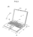
FIG. 3 shows the notebook PC 101 in the
electronic equipment system 100. FIG. 4A shows a left
side of the notebook PC 101, and FIG. 4B shows a right
side of the notebook PC 101. FIG. 5A shows a back of
the notebook PC 101, and FIG. 5B shows a bottom of the
notebook PC 101.
-
A description will now be given of the
notebook PC 101 in the electronic equipment system 100
of the present embodiment.
-
The notebook PC 101 generally has a
host PC 113 and a display part 114. The display part
114 is rotatably supported on the host PC 113. The
display part 114 is rotatable on the host PC 113 in
directions indicated by the arrows D1 and D2 in FIG.
3. When the notebook PC 101 is carried by the user,
the display part 114 is rotated on the host PC 113 in
the direction D1. The host PC 113 is fully covered by
the display part 114, and they are placed in a flat
condition as shown in FIG. 4B.
-
When the notebook PC 101 is used by the
user, the display part 114 is rotated on the host PC
113 in the direction D2. Internal surfaces of the
host PC 113 and the display part 114 are uncovered as
shown in FIG. 4A, and the notebook PC 101 can operate
in this condition.
-
When the notebook PC 101 is set in the
condition shown in FIG. 3, a keyboard 115 and a
pointing device 116 on the top of the host PC 113 are
uncovered. During operation of the notebook PC 101,
the user can input a command and data to the notebook
PC 101 by using the keyboard 115, and can move a
pointer "P" on the monitor of the display part 114 by
using the pointing device 116. An operating state
indicator 117 is provided at a rear position on the
top of the host PC 113. The operating state indicator
117 provides an indication of an operating state of
the notebook PC 101.
-
As shown in FIG. 4A, a power switch 118
is provided on the left side of the host PC 113. When
the power switch 118 is turned on or off, the
operation of the notebook PC 101 is started or
terminated.
-
As shown in FIG. 4B, a volume control
119, a headphone jack 120, a microphone jack 121, a
LINE-IN jack 122, an anti-theft lock 123, a modular
connector 124, a PC card lock 125, a PC card slot 126
and a PC card eject button 127 are provided on the
right side of the host PC 113.
-
The volume control 119 acts to adjust
the volume of a ringing signal or a sound signal. A
headphone (not shown) is connected to the headphone
jack 120. A microphone (not shown) is connected to
the microphone jack 121. A sound input connector (not
shown) is connected to the LINE-IN jack 122, and a
sound signal output by an external device is supplied
through the sound input connector to the notebook PC
101. An anti-theft cable (not shown) is connected to
the anti-theft lock 123. A telephone line connecting
jack (not shown) is connected to the modular jack 124.
Any of the PC cards, including the SCSI card 110, the
IC memory card 111 and the LAN card 112, is inserted
into the PC card slot 126. The PC card lock 125 acts
to lock the inserted PC card in the PC card slot 126
and prevent separation of the PC card from the PC card
slot 126.
-
As shown in FIG. 5A, an infrared
communication port 128, a USB (universal serial bus)
connector 129, an expansion keyboard/mouse connector
130, a floppy disk drive connector 131, a serial
interface connector 132, a parallel interface
connector 133, a CRT interface connector 134, a DC-IN
connector 135 and an expansion connector cover 136 are
provided on the back of the host PC 113.
-
The infrared communication port 128
provides an interface needed to perform an infrared
communication. A peripheral device (not shown) which
is in conformity with USB (universal serial bus)
standard is connected to the USB connector 129. The
ten-key board 108 or the mouse 109 is connected to the
expansion keyboard/mouse connector 130. The floppy
disk drive unit 105 is connected to the floppy disk
drive connector 131. An external device (not shown)
having an interface in conformity with RS-232C
standard is connected to the serial interface
connector 132. The printer 107 or the like is
connected to the parallel interface connector 133.
The color CRT display 106 is connected to the CRT
interface connector 134. An AC adapter (not shown)
which externally supplies source power to the notebook
PC 101 is connected to the DC-IN connector 135. The
expansion connector cover 136 provides protection for
the connectors on the back of the host PC 113 when the
notebook PC 101 is carried by the user.
-
As shown in FIG. 5B, an expansion unit
connector 137, an expansion RAM (random access memory)
slot 138, a built-in battery pack lock 139, an unlock
button 140, a built-in battery pack slot 141 and a
built-in hard disk drive slot 142 are provided on the
bottom of the notebook PC 101.
-
The expansion station 102 and the
compact bay case 104 are connected to the expansion
unit connector 137. An expansion RAM module (not
shown) is inserted into the expansion RAM slot 138.
The battery pack lock 139 acts to lock the battery
pack 103 in the battery pack slot 141 when the battery
pack 103 is inserted into the battery pack slot 141.
The unlock button 140 acts to unlock the battery pack
103. The battery pack 103 is inserted into the
battery pack slot 141. A built-in hard disk drive
unit 143 is inserted into the hard disk drive slot
142.
-
Further, as shown in FIG. 3, a liquid
crystal display 144 is provided on the internal
surface of the display part 114, and an image is
displayed on the liquid crystal display 144. The
notebook PC 101 includes a CPU, a RAM, a ROM, an
interface circuit and a communication circuit which
are incorporated in the host PC 113, and these
elements enable the notebook PC 101 to carry out
information processing.
-
FIG. 6 shows the expansion station 102
in the electronic equipment system 100 of the present
embodiment. FIG. 7 shows a back of the expansion
station 102 in the electronic equipment system 100.
-
A description will now be given of the
expansion station 102 in the electronic equipment
system 100 of the present embodiment.
-
As shown in FIG. 6, a built-in battery
pack slot 145, a built-in battery pack lock 146, a
connector 147, connector locks 148, a CD-ROM drive
149, a CD-ROM eject button 150, a release button 151,
a release enable lamp 152, a floppy disk drive 153, a
floppy disk eject button 154, a PC card slot 155 and a
release lever 156 are provided on the expansion
station 102.
-
The battery pack 103 is inserted into
the battery pack slot 145. The battery pack slot 145
is provided for mounting the battery pack 103 on the
expansion station 102, and the battery pack 103
supplies power to the expansion station 102 and the
notebook PC 101. The battery pack lock 146 acts to
lock the battery pack 103 in the battery pack slot
145. The connector 147 is connected to the expansion
unit connector 137 on the bottom of the host PC 113,
so that the expansion station 102 and the host PC 113
are connected to each other. The connector locks 148
are fitted to recessed portions 209 (FIG. 5B) of the
bottom of the host PC 113, so that the expansion
station 102 is mechanically connected to the host PC
113. A CD-ROM 157 is inserted into the CD-ROM drive
149, and the CD-ROM drive 149 acts to read information
from the CD-ROM 157. The CD-ROM eject button 150 acts
to eject the CD-ROM 157 from the CD-ROM drive 149.
The release button 151 acts to release the expansion
station 102 from the notebook PC 101. The release
enable lamp 152 is comprised of an LED (light emitting
diode). The release enable lamp 152 is turned on when
the notebook PC 101 is set in a condition that the
expansion station 102 can be removed from the notebook
PC 101. A floppy disk 158 is inserted into the floppy
disk drive 153, and the floppy disk drive 153 acts to
read information from or write information to the
floppy disk 158. The floppy disk eject button 154
acts to eject the floppy disk 158 from the floppy disk
drive 153. A PC card 159 is inserted into the PC card
slot 155. The release lever 156 is pulled by the user
before the expansion station 102 is released from the
notebook PC 101. The release lever 156 acts to
release the mechanical connection between the notebook
PC 101 and the expansion station 102.
-
As shown in FIG. 7, an anti-theft lock
160, a security lock 161, an LAN connector 162, a USB
connector 163, an expansion keyboard connector 164, a
mouse connector 165, a serial interface connector 166,
a sound output terminal 167, a video output terminal
168, a parallel interface connector 169, a CRT
connector 170, a DC-IN connector 171 and ventilation
holes 172 are provided on the back and the side of the
expansion station 102.
-
An anti-theft cable (not shown) is
connected to the anti-theft lock 160. The security
lock 161 acts to lock the connection of the anti-theft
cable and the anti-theft lock 160 when the anti-theft
cable is fixed to the anti-theft lock 160. An LAN
cable (not shown) is connected to the LAN connector
162. A peripheral device (not shown) which is in
conformity with USB standard is connected to the USB
connector 163. The ten-key board 108 is connected to
the expansion keyboard connector 164. The mouse 109
is connected to the mouse connector 165. An external
device (not shown) having an interface in conformity
with RS-232C standard is connected to the serial
interface connector 166. A speaker (not shown) or the
like is connected to the sound output terminal 167. A
sound signal is output from the sound output terminal
167. A video board (not shown) or the like is
connected to the video output terminal 168. A video
signal is output from the video output terminal 168.
A printer or the like having a parallel port is
connected to the parallel interface connector 169.
The CRT display 106 is connected to the CRT connector
170. An AC adapter (not shown) which externally
supplies source power to the expansion station 102 is
connected to the DC-IN connector 171. The ventilation
holes 172 act to circulate air within the expansion
station 102 so as to cool the inside of the expansion
station 102.
-
When the AC adapter is connected to the
expansion station 102, the source power can be
externally supplied to the expansion station 102 by
the AC adapter. When the battery pack 103 is inserted
into the battery pack slot 145, power from the battery
pack 103 can be supplied to the expansion station 102.
In addition, the battery pack 103 inserted into the
battery pack slot 145 can be recharged with the source
power supplied by the AC adapter.
-
FIG. 8 shows the compact bay case 104
in the electronic equipment system 100. FIG. 9 shows
a bottom of the compact bay case 104 in the electronic
equipment system 100. FIG. 10 shows a side of the
compact bay case 104 in the electronic equipment
system 100.
-
In the accompanying drawings, including
FIG. 8, FIG. 9 and FIG. 10, the arrow X1 indicates a
left direction of the notebook PC 101, the arrow X2
indicates a right direction of the notebook PC 101,
the arrow Y1 indicates a rear direction of the
notebook PC 101, the arrow Y2 indicates a front
direction of the notebook PC 101, the arrow Z1
indicates an upward direction of the notebook PC 101,
and the arrow Z2 indicates a downward direction of the
notebook PC 101.
-
A description will now be given of the
compact bay case 104 in the electronic equipment
system 100 of the present embodiment.
-
The compact bay case 104 has a length
"A1" which is equivalent to a length "A2" of the
notebook PC 101, a width "B1" which is approximately
half of a width "B2" of the notebook PC 101, and a
height "C1" which is equivalent to a height "C2" of
the notebook PC 101. The compact bay case 104 is
remarkably small in size. The compact bay case 104 is
approximately half as large as the notebook PC 101.
The compact bay case 104 is provided in a flat
rectangular formation. The notebook PC 101 with the
compact bay case 104 attached thereto is easily
portable.
-
As shown in FIG. 8, the compact bay
case 104 generally has an expansion bay 201, a battery
pack slot 202, a connector 203, and lugs 204. The
expansion bay 201 includes an insertion opening 205 on
the left side of the compact bay case 104. An
optional component unit, such as a floppy disk drive
unit or a CD-ROM drive unit, is inserted through the
insertion opening 205 into the expansion bay 201, and
the inserted component unit provides an extended
function of the notebook PC 101. The floppy disk
drive unit and the CD-ROM drive unit which are
provided as the optional component unit on the compact
bay case 104 will be described later.
-
The battery pack slot 202 is provided
on the top of the compact bay unit 104. The battery
pack 103 is inserted into the battery pack slot 202,
and the battery pack 103 supplies power to the
optional component unit on the compact bay case 104
and to the notebook PC 101. In the battery pack slot
202, a connector 206 and connecting portions 207 are
provided. The connector 206 is electrically connected
to the battery pack 103 when inserted into the battery
pack slot 202. The connecting portions 207 act to
lock the battery pack 103 to the battery pack slot 202
when inserted. An operation lever 208 is provided on
the periphery of the battery pack slot 202. When the
operation lever 208 is manipulated by the user, the
battery pack 103 is unlocked from the connecting
portions 207.
-
The connector 203 on the top of the
compact bay case 104 is connected to the connector 137
on the bottom of the notebook PC 101 when the compact
bay case 104 is attached to the notebook PC 101. The
compact bay case 104 electrically connects the
optional component unit to the notebook PC 101 through
the connection of the connector 203 and the connector
137. The lugs 204 on the top of the compact bay case
104 are fitted to the recessed portions 209 on the
bottom of the notebook PC 101. The compact bay unit
104 is mechanically connected to the notebook PC 101
by the connection of the lugs 204 and the recessed
portions 209.
-
As shown in FIG. 9, an operation button
210 which is engaged with the lugs 204 is provided on
the bottom of the compact bay case 104. When the
operation button 210 is pressed by the user, the lugs
of the compact bay case 104 are released from the
recessed portions 209 of the notebook PC 101. Hence,
when the user intends to detach the compact bay case
104 from the notebook PC 101, the user presses the
operation button 210.
-
A lock lever 211 is provided on the
bottom of the compact bay case 104 adjacent to the
operation button 210. The lock lever 211 is
manipulated by the user to lock the operation button
210 at its locked position. The lock lever 211 acts
to prevent erroneous detachment of the compact bay
case 104 from the notebook PC 101 when the operation
button 210 is erroneously touched by the user.
-
A pair of leg portions 212 are provided
on the bottom of the compact bay case 104, and the leg
portions 212 are rotatably supported on hinges such
that the leg portions 212 are rotatable between a
retracted position and a raised position. When the
leg portions 212 on the bottom of the compact bay case
104 are set at the raised position, the keyboard 115
on the internal surface of the notebook PC 101 can be
placed in a slanted condition.
-
As shown in FIG. 10, an undocking
request button 213 and an undocking indicator 214 are
provided on the side of the compact bay case 104. The
undocking indicator 214 is comprised of an LED (light
emitting diode). The undocking request button 213 is
pressed by the user, and the undocking request button
213 at that time acts to activate an undocking request
generating unit (which will be described later) which
requests the notebook PC 101 to permit detachment of
the compact bay case 104 from the notebook PC 101.
The undocking indicator 214 is turned on to provide an
indication that the detachment of the compact bay case
104 from the notebook PC 101 is permitted by the
notebook PC 101.
-
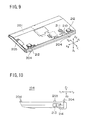
FIG. 11A and FIG. 11B show a floppy
disk drive unit 215 which is an optional component
unit mounted on the compact bay case 104. FIG. 11A
shows a bottom of the floppy disk drive unit 215, and
FIG. 11B shows a top of the floppy disk drive unit
215.
-
The floppy disk drive unit 215 is
inserted in the direction X1 through the insertion
opening 205 of the compact bay case 104 into the
expansion bay 201. The inserted floppy disk drive
unit 215 provides an extended function of the notebook
PC 101. The floppy disk drive unit 215 includes, as
shown in FIG. 11A and FIG. 11B, a connector 216 and a
floppy disk insertion opening 217. As shown in FIG.
8, the compact bay case 104 includes a connector 216A
provided at an end of the expansion bay 201. When the
floppy disk drive unit 215 is mounted in the expansion
bay 201 of the compact bay case 104, the connector 216
is connected to the connector 216A, so that the floppy
disk drive unit 215 and the notebook PC 101 are
interconnected by the connection of the connector 216
and the connector 216A. Further, when the floppy disk
drive unit 215 is mounted in the expansion bay 201,
the floppy disk insertion opening 217 is located at
the insertion opening 205 of the compact bay case 104.
A floppy disk (not shown) can be easily inserted into
or withdrawn from the floppy disk drive unit 215
through the floppy disk insertion opening 216.
-
FIG. 12 shows a CD-ROM drive unit 218
which is another optional component unit mounted on
the compact bay case 104.
-
The CD-ROM drive unit 218 is inserted
in the direction X1 through the insertion opening 205
of the compact bay case 104 into the expansion bay
201. The inserted CD-ROM drive unit 218 provides an
extended function of the notebook PC 101. The CD-ROM
drive unit 218 includes, as shown in FIG. 12, a
connector 219 and a CD-ROM insertion part 220. When
the CD-ROM drive unit 218 is mounted in the expansion
bay 201 of the compact bay case 104, the connector 219
is connected to the connector 216A, so that the CD-ROM
drive unit 218 and the notebook PC 101 are
interconnected by the connection of the connector 219
and the connector 216A. Further, when the CD-ROM
drive unit 218 is mounted in the expansion bay 201,
the CD-ROM insertion part 220 is located at the
insertion opening 205 of the compact bay case 104. A
CD-ROM (not shown) can be easily inserted into or
withdrawn from the CD-ROM drive unit 218 through the
CD-ROM insertion part 220.
-
FIG. 13A and FIG. 13B show the battery
pack 103 in the electronic equipment system 100. In
FIG. 13A, the battery pack 103 is viewed from a lower
position. In FIG. 13B, the battery pack 103 which is
turned upside down is viewed from an upper position.
-
The battery pack 103 is provided in a
generally rectangular formation. The battery pack 103
has a notch portion 173 which is provided to easily
identify the front and rear faces of the battery pack
103. The battery pack 103 includes, as shown in FIG.
13A, a terminal 174 on the front face of the battery
pack 103. The terminal 174 is electrically connected
to one of the notebook PC 101, the expansion station
102 and the compact bay case 104, when the battery
pack 103 is inserted in one of the battery pack slot
141, the battery pack slot 145 and the battery pack
slot 202.
-
The battery pack 103 includes, as shown
in FIG. 13A, a pair of recessed portions 175 and 176
on the front face of the battery pack 103. The
battery pack 103 includes, as shown in FIG. 13B, a
pair of recessed portions 177 and 178, and a recessed
portion 179 on the rear face of the battery pack 103.
The recessed portions 175 through 179 act to
mechanically connect the battery pack 103 to the
battery pack slot 141, 145 or 202 of the related one
of the notebook PC 101, the expansion station 102 and
the compact bay case 104.
-
FIG. 14 shows a battery pack slot in
the electronic equipment system 100.
-
In the electronic equipment system 100
of the present embodiment, the battery pack slot 141
of the notebook PC 101, the battery pack slot 145 of
the expansion station 102 and the battery pack slot
202 of the compact bay case 104 are identical in
shape. The battery pack 103 can be inserted into any
of the battery pack slots 141, 145 and 202. For the
sake of convenience, a description will now be given
of the battery pack slot 141 as a representative one
of the battery pack slots 141, 145 and 202.
-
As shown in FIG. 14, the battery pack
slot 141 includes a recess 180, a contact terminal
181, connecting portions 182 and the battery pack lock
139. The recess 180 is formed on either the top or
the bottom of one of the notebook PC 101, the
expansion station 102 and the compact bay case 104.
The recess 180 has a configuration that is the same as
the configuration of the battery pack 103. The
contact terminal 181 is electrically connected to the
terminal 174 of the battery pack 103 when the battery
pack 103 is inserted into the recess 180. The
connecting portions 182 are fitted to the recessed
portions 175-179 of the battery pack 103 when the
battery pack 103 is inserted into the recess 180. The
battery pack lock 139 is operated by the user, and the
battery pack lock 139 locks the battery pack 103 in
the battery pack slot 141 by the connection of the
connecting portions 182 and the recessed portions 175-179.
When the battery pack lock 139 is loosened by
the user, the connecting portions 182 are disconnected
from the recessed portions 175-179 so that the battery
pack 103 can be detached from the battery pack slot
141.
-
FIG. 15 is a diagram for explaining
insertion of the battery pack 103 into and withdrawal
of the battery pack 103 from the battery pack slot
141.
-
As shown in FIG. 15, when inserting the
battery pack 103 into the battery pack slot 141 in a
direction indicated by the arrow 183, the notch
portion 173 of the battery pack 103 is matched with a
corresponding portion of the recess 180 of the battery
pack slot 141. While the notch portion 173 is matched
with the corresponding portion of the recess 180, the
battery pack 103 is rotated in a direction indicated
by the arrow 184. Then, the battery pack 103 is
completely inserted into the recess 180 of the battery
pack slot 141.
-
FIG. 16 is a diagram for explaining
attaching of the compact bay case 104 to and detaching
of the compact bay case 104 from the notebook PC 101.
-
In the electronic equipment system 100
of the present embodiment, the compact bay case 104 is
attached to the bottom of the notebook PC 101 when
used. The floppy disk drive unit 215 or the CD-ROM
drive unit 218 is mounted in the expansion bay 201 of
the compact bay case 104 as an optional component unit
221 which provides an extended function of the
notebook PC 101.
-
The electronic equipment system 100 of
the present embodiment is characterized in that the
optional component unit 221 (the floppy disk drive
unit 215 or the CD-ROM drive unit 218) is detachable
from the compact bay case 104 when the compact bay
case 104 is attached to the notebook PC 101 which is
in an operating condition.
-
When the compact bay case 104
containing the optional component unit 221 which is
mounted in the expansion bay 201 is attached to the
notebook PC 101, or when the optional component unit
221 is inserted into the vacant expansion bay 201 of
the compact bay case 104 which is attached to the
notebook PC 101, the compact bay case 104 transmits a
connection request to the notebook PC 101 so that the
notebook PC 101 recognizes the presence of the
optional component unit 221 in the electronic
equipment system 100.
-
On the other hand, when the compact bay
case 104 containing the optional component unit 221
which is mounted in the expansion bay 201 is detached
from the notebook PC 101, or when the optional
component unit 221 is detached from the compact bay
case 104 which is attached to the notebook PC 101, the
user presses the undocking request button 213 on the
side of the compact bay case 104. When the undocking
request button 213 is pressed, the compact bay case
104 transmits an undocking request to the notebook PC
101, and the undocking request causes the notebook PC
101 to permit the detachment of the optional component
unit 221 from the compact bay case 104. The compact
bay case 104 receives an undocking acknowledge signal
output by the notebook PC 101, and the undocking
acknowledge signal indicates that the notebook PC 101
has permitted the detachment. Upon receipt of the
undocking acknowledge signal, the undocking indicator
LED 214 is turned on to provide an indication that the
detachment of the optional component unit 221 from the
compact bay case 104 is permitted. Hence, the
optional component unit 221 can be detached from the
compact bay case 104 when the compact bay case 104 is
attached to the notebook PC 101 which is in an
operating condition.
-
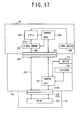
FIG. 17 is a block diagram of an
essential part of the electronic equipment system 100
which deals with the attaching of the compact bay case
104 to and the detaching of the compact bay case 104
from the notebook PC 101.
-
As shown in FIG. 17, the connector 137
of the notebook PC 101 and the connector 203 of the
compact bay case 104 are connected to each other, and
the connector 216A of the compact bay case 104 and the
connector 216 (or 219) of the optional component unit
221 are connected to each other.
-
In the notebook PC 101, the connector
137 is connected through a PCI (peripheral component
interconnect) bus 222 to a signal buffer 223, and the
signal buffer 223 is connected through a PCI bus 222a
to a CPU 224. A control unit 225 is connected to each
of the CPU 224, the signal buffer 223 and the
connector 137, and various control signals are
transmitted between the control unit 225 and these
elements 224, 223 and 137. Further, an input device
229 is connected to the CPU 224.
-
The control unit 225 executes a control
process when attaching the compact bay case 104 (or
the expansion station 102) to the notebook PC 101 or
when detaching the compact bay case 104 (or the
expansion station 102) from the notebook PC 101.
-
In the compact bay case 104, the
connector 203 is connected through a PCI bus 226 to
the connector 216A. The connector 203 is also
connected to a control unit 227, and the control unit
227 is connected to the connector 216A. Further, the
undocking request button (SWITCH) 213 is connected to
the control unit 227, and the undocking indicator LED
(INDICATOR) 214 is connected to the control unit 227.
-
The control unit 227 executes a control
process when attaching the compact bay case 104 to the
notebook PC 101 or when detaching the compact bay case
104 from the notebook PC 101.
-
In the optional component unit 221, the
connector 216 (or 219) is connected to a drive 228.
The drive 228 provides an extended function of the
notebook PC 101, that is: the floppy disk drive
function or the CD-ROM drive function.
-
FIG. 18 shows a control process
executed by the control unit 227 of the compact bay
case 104 when the compact bay case 104 is attached to
the notebook PC 101 during operation.
-
When the connector 137 of the notebook
PC 101 and the connector 203 of the compact bay case
104 are connected to each other and the optional
component unit 221 is mounted in the expansion bay 201
of the compact bay case 104, the control unit 227 is
power-on reset by the power supplied from the notebook
PC 101. As shown in FIG. 18, the control unit 227 at
step S1-1 detects whether it is power-on reset. When
the result at the step S1-1 is negative, the detection
at step S1-1 is repeated. When the result at step S1-1
is affirmative, the control unit 227 at step S1-2
transmits a connection request to the control unit 225
of the notebook PC 101 via the connectors 203 and 137.
After the connection request is output to the notebook
PC 101, the control process of FIG. 18 is terminated.
-
FIG. 19 shows a control process
executed by the control unit 225 of the notebook PC
101 when the compact bay case 104 is attached to the
notebook PC 101 during operation.
-
As shown in FIG. 19, the control unit
225 at step S2-1 detects whether a connection request
from the control unit 227 is received at the notebook
PC 101. When the result at the step S2-1 is negative,
the detection at step S2-1 is repeated. When the
result at step S2-1 is affirmative, the control unit
225 at step S2-2 performs a bus connection by
controlling the signal buffer 223 so as to connect the
PCI bus 222a and the PCI bus 226 of the compact bay
case 104. After the bus connection is performed at
step S2-2, the control unit 225 at step S2-3 causes
the CPU 224 to recognize the presence of the drive 228
of the optional component unit 221. After the drive
recognition is performed at step S2-3, the presence of
the drive 228 of the optional component unit 221
attached to the notebook PC 101 via the compact bay
case 104 is recognized by the CPU 224 of the notebook
PC 101. Then, the control process of FIG. 19 is
terminated.
-
FIG. 20 shows a control process
executed by the control unit 227 of the compact bay
case 104 when the compact bay case 104 is detached
from the notebook PC 101 during operation.
-
When the compact bay case 104
containing the optional component unit 221 which is
mounted in the expansion bay 201 is detached from the
notebook PC 101, or when the optional component unit
221 is detached from the compact bay case 104 which is
attached to the notebook PC 101, the user presses the
undocking request button 213 on the side of the
compact bay case 104.
-
As shown in FIG. 20, the control unit
227 at step S3-1 detects whether the undocking request
button 213 is pressed by the user. When the result at
step S3-1 is affirmative, the control unit 227 at step
S3-2 transmits an undocking request signal to the
control unit 225 of the notebook PC 101. Otherwise
the detection at step S3-1 is repeated.
-
After the undocking request signal is
transmitted at step S3-2, the control unit 227 at step
S3-3 detects whether an undocking acknowledge signal
output by the control unit 225 is received at the
compact bay case 104. When the result at step S3-3 is
affirmative, the control unit 227 at step S3-4 turns
on the undocking indicator 214. Otherwise the
detection at step S3-3 is repeated. If the undocking
indicator 214 is turned on, an indication that the
detachment of the optional component unit 221 from the
compact bay case 104 is permitted by the notebook PC
101 is provided for the user.
-
After the undocking indicator 214 is
turned on at step S3-4, the control unit 227 at step
S3-5 detects whether the compact bay case 104 is
detached from the notebook PC 101, and detects whether
the optional component unit 221 is detached from the
compact bay case 104. The detections of the
detachment at step S3-5 are performed by detecting the
source power supplied from the notebook PC 101 through
the compact bay case 104 to the optional component
unit 221 and supplied through the optional component
unit 221 to the control unit 227. When the compact
bay case 104 is detached from the notebook PC 101, the
source power from the notebook PC 101 is not supplied
to the control unit 227. When the optional component
unit 221 is detached from the compact bay case 104,
the source power from the notebook PC 101 is not
supplied to the control unit 227. Hence, by detecting
the non-supplying of the source power to the control
unit 227, the detections of the detachment at step S3-5
can be performed by the control unit 227.
-
When it is detected at step S3-5 that
the compact bay case 104 is detached from the notebook
PC 101 or that the optional component unit 221 is
detached from the compact bay case 104, the control
unit 227 at step S3-6 turns off the undocking
indicator 214. Otherwise the steps S3-4 and S3-5 are
repeated. After the step S3-6 is performed, the
control process of FIG. 20 is terminated.
-
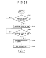
FIG. 21 shows a control process
executed by the control unit 225 of the notebook PC
101 when the compact bay case 104 is detached from the
notebook PC 101 during operation.
-
As shown in FIG. 21, the control unit
225 at step S4-1 detects whether an undocking request
signal output by the control unit 227 is received.
When the result at step S4-1 is affirmative, the
control unit 225 at step S4-2 causes the CPU 224 to
perform an undocking process. Otherwise the detection
at step S4-1 is repeated. During the undocking
process by the CPU 224, the recognition of the drive
228 of the optional component unit 221 is canceled.
-
After the step S4-2 is performed, the
control unit 225 at step S4-3 detects whether the
undocking process by the CPU 224 is complete. When
the result at step S4-3 is affirmative, the control
unit 225 at step S4-4 transmits an undocking
acknowledge signal to the control unit 227 of the
compact bay case 104. Otherwise the detection at step
S4-3 is repeated. The undocking acknowledge signal,
transmitted to the control unit 227, indicates that
the notebook PC 101 has permitted the detachment of
the compact bay case 104 from the notebook PC 101 or
the detachment of the optional component unit 221 from
the compact bay case 104.
-
After the undocking acknowledge signal
is transmitted to the control unit 227 at step S4-4,
the control unit 225 at step S4-5 performs a bus
disconnection by controlling the signal buffer 223 so
as to disconnect the PCI bus 222a from the PCI bus 226
of the compact bay case 104. After the step S4-5 is
performed, the control process of FIG. 21 is
terminated.
-
In the above-described embodiment, the
optional component unit 221 is detachable from the
compact bay case 104 when the compact bay case 104 is
connected to the notebook PC 101 which is in an
operating condition. When the optional component unit
221 in the compact bay case 104 is exchanged for a new
component unit, it is not necessary to stop operation
of the notebook PC 101 or turn off the power switch
118 of the notebook PC 101. It is possible to
exchange the optional component unit 221 for the new
component unit even when the notebook PC 101 is
operating. The electronic equipment system 100 of the
above-described embodiment is effective in providing
an adequate level of operability for the user.
-
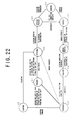
FIG. 22 shows a transition of docking
conditions of the electronic equipment system 100.
-
The electronic equipment system 100 of
the present embodiment during operation is controlled
to have a transition of docking conditions shown in
FIG. 22. The docking conditions of FIG. 22 include a
removed state S1, an attached state S2, a docking
process state S3, a docked state S4, an undocking
process state S5, an isolated state S6, an undocked
state S7, and a suspended state S8. The electronic
equipment system 100 during operation is controlled to
be in one of these states S1-S8.
-
When the electronic equipment system
100 is in the removed state S1, the expansion station
102 is detached from the notebook PC 101, the compact
bay case 104 is detached from the notebook PC 101, or
the optional component unit 221 is detached from the
compact bay case 104 while the compact bay case 104 is
attached to the notebook PC 101.
-
The attached state S2 is a transient
state of the electronic equipment system 100. In the
attached state S2, the notebook PC 101 is connected to
the expansion station 102 but the PCI bus connection
between the notebook PC 101 and the expansion station
102 is not yet started, or the optional component unit
221 is connected to the compact bay case 104 which is
attached to the notebook PC 101 but the PCI bus
connection between the notebook PC 101 and the compact
bay case 104 is not yet started.
-
When the electronic equipment system
100 is in the docking process state S3, the PCI bus
connection between the notebook PC 101 and the
expansion station 102 is being performed, or the PCI
bus connection between the notebook PC 101 and the
compact bay case 104 is being performed. After the
PCI bus connection is complete, the electronic
equipment system 100 changes from the docking process
state S3 to the docked state S4. The timing of
completion of the PCI bus connection is notified to
the software of the notebook PC 101 by an event
DOCKSMI# issued by the control unit 225 of the
notebook PC 101. The event DOCKSMI# is issued to
notify the software of the completion of the PCI bus
connection.
-
The docked state S4 is a state of the
electronic equipment system 100 in which the docking
of the expansion station 102 and the notebook PC 101
is complete, or the docking of the optional component
unit 221 and the compact bay case 104 attached to the
notebook PC 101 is complete. The completion of the
docking means that both the PCI bus connection and the
docking notification to the software of the notebook
PC 101 are carried out. When the electronic equipment
system 100 changes to the docked state S4, the
configuration of the resources of the electronic
equipment system 100 is restarted. As a result of the
configuration, the devices newly docked to the
electronic equipment system 100 are recognized by the
CPU 224 of the notebook PC 101 so that the devices are
available.
-
The electronic equipment system 100
changes from the docked state S4 to the undocking
process state S5 at a start of an undocking process
when the undocking request button on the compact bay
case 104 or the expansion station 102 is pressed by
the user or when an undocking request icon on the
display monitor of the notebook PC 101 is clicked by
the user. The undocking process is started by an
event UNDKREQ# issued by the software of the notebook
PC 101. During the undocking process, interrupt
requests are sent to device drivers recognized by the
operating system kernel, and the PCI bus isolation
request for the undocking is issued by the BIOS (basic
input output system) and the device drivers after the
interrupt requests are accepted. After the undocking
process is complete, the electronic equipment system
100 changes from the undocking process state S5 to the
isolated state S6.
-
When the electronic equipment system
100 is in the isolated state S6, the PCI bus isolation
between the notebook PC 101 and the expansion station
102 is being performed, or the PCI bus isolation
between the notebook PC 101 and the compact bay case
104 is being performed. After the PCI bus isolation
is complete, an event UNDKSMI# is issued to notify the
software of the notebook PC 101 that the undocking is
performed. After the notification of the undocking is
performed, the electronic equipment system 100 changes
from the isolated state S6 to the undocked state S7.
-
When the electronic equipment system
100 is in the undocked state S7, the PCI bus isolation
between the notebook PC 101 and the expansion station
102 is complete but the expansion station is connected
to the notebook PC 101, or the PCI bus isolation
between the optional component unit 221 and the
compact bay case 104 attached to the notebook PC 101
is complete but the optional component unit 221 is
connected to the compact bay case 104. During the
undocked state S7, all the resources of the expansion
station 102 or all the resources of the compact bay
case 104 are not recognized by the notebook PC 101.
When the electronic equipment system 100 is in the
undocked state S7, the undocking indicator LED is
turned on.
-
The electronic equipment system 100
changes from the undocked state S7 to the removed
state S1 when the expansion station 102 is detached
from the notebook PC 101 or when the compact bay case
104 is detached from the notebook PC 101. When the
electronic equipment system 100 is in the undocked
state S7 and a suspend command is issued, the
electronic equipment system 100 changes to the
suspended state S8.
-
When the electronic equipment system
100 is in the suspended state S8, the source power is
not supplied to most of the resources of the expansion
station 102 connected to the notebook PC 101, or the
source power is not supplied to most of the resources
of the compact bay case 104 connected to the notebook
PC 101. During the suspended state S8, the source
power is supplied to only the portion of the expansion
station 102 or the compact bay case 104, needed to
monitor the docking conditions of the electronic
equipment system 100.
-
When the electronic equipment system
100 changes from the docked state S4 to the suspended
state S8, the PCI bus between the notebook PC 101 and
the expansion station 102 or the PCI bus between the
optional component unit 221 and the compact bay case
104 is automatically isolated. In order to allow the
electronic equipment system 100 to change from the
suspended state S8 to the docked state S4, it is
necessary to perform the PCI bus connection between
the notebook PC 101 and the expansion station 102 or
the PCI bus connection between the optional component
unit 221 and the compact bay case 104. Hence, the
electronic equipment system 100 must change from the
suspended state S8 to the docked state S4 through the
docking process state S3.
-
When the electronic equipment system
100 is in the undocked state S7 and a suspend command
is issued, the electronic equipment system 100 changes
to the suspended state S8. Further, when the
electronic equipment system 100 is in the suspended
state S8 and a resuming operation is performed, the
electronic equipment system 100 changes to the
attached state S2. At this time, an event DKSITSMI#
is issued to notify the software of the notebook PC
101 that the docking is performed.
-
The electronic equipment system 100 of
the present embodiment during operation changes from
one of the docking conditions to another due to
occurrence of any of the events (or the interrupt
requests) DKSITSMI#, UNDKREQ#, DOCKSMI# and UNDKSMI#.
-
The event DKSITSMI# is issued to notify
the software of the notebook PC 101 that the docking
is performed. For example, when the expansion station
102 is attached to the notebook PC 101, or when the
optional component unit 221 is attached to the compact
bay case 104 connected to the notebook PC 101, the
attachment of the expansion station 102 or the
attachment of the optional component unit 221 is
notified to the software of the notebook PC 101. The
transition of the docking conditions of the electronic
equipment system 100 as described above is caused by
the event DKSITSMI#.
-
The event UNDKREQ# is issued to notify
the software of the notebook PC 101 that the undocking
request button is pressed. The transition of the
docking conditions of the electronic equipment system
100 as described above is caused by the event
UNDKREQ#.
-
The event DOCKSMI# is issued to notify
the software of the notebook PC 101 that the PCI bus
between the expansion station 102 and the notebook PC
101 or the PCI bus between the optional component unit
221 of the compact bay case 104 and the notebook PC
101 is connected to each other. The transition of the
docking conditions of the electronic equipment system
100 as described above is caused by the event
DOCKSMI#.
-
The event UNDKSMI# is issued to notify
the software of the notebook PC 101 that the PCI bus
between the expansion station 102 and the notebook PC
101 or the PCI bus between the optional component unit
221 of the compact bay case 104 and the notebook PC
101 is disconnected from to each other. The
transition of the docking conditions of the electronic
equipment system 100 as described above is caused by
the event UNDKSMI#.
-
The interrupt request signals of the
events DKSITSMI#, UNDKREQ#, DOCKSMI# and UNDKSMI# when
each of the events is issued are respectively
transmitted to a connection controller 302 (which will
be described later) of the notebook PC 101.
-
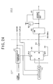
FIG. 23 shows a configuration of the
control unit 225 of the notebook PC 101 in the
electronic equipment system 100 of the present
embodiment.
-
As shown in FIG. 23, the control unit
225 of the notebook PC 101 generally has a connection
controller 302, a docking sequencer 303, and a
notification circuit 304. The control unit 225 of the
notebook PC 101 in FIG. 17 is referred to as the
connection circuit 301 in FIG. 23. The CPU 224 of the
notebook PC 101 in FIG. 17 is referred to as the CPU
305 in FIG. 23.
-
In the connection circuit 301 of FIG.
23, the polling of the events DKSITSMI#, UNDKREQ#,
DOCKSMI# and UNDKSMI# is performed by the connection
controller 302 at time intervals of 10 ms. Event time
the interrupt request signal of one of the events
DKSITSMI#, UNDKREQ#, DOCKSMI# and UNDKSMI# is
detected, the connection controller 302 causes the
notification circuit 304 to output an interrupt signal
to the software of the notebook PC 101 processed by
the CPU 305.
-
The docking sequencer 303 is initiated
in accordance with an instruction output by the CPU
305, and outputs the interrupt request signal of one
of the events DOCKSMI# and UNDKSMI# to the connection
controller 302. Hence, the transition of the docking
conditions of the electronic equipment system 100 as
described above is caused by the docking notification
event DOCKSMI# or the undocking notification event
UNDKSMI#.
-
In response to the request output by
the connection controller 302, the notification
circuit 304 supplies an interrupt signal to the
software of the notebook PC 101 which is processed by
the CPU 305. In order to detect the cause of the
interrupt supplied, the software issues a query
command to the connection controller 302, and receives
a return value of the query command from the
connection controller 302. When a return value which
corresponds to one of the events DKSITSMI#, UNDKREQ#,
DOCKSMI# and UNDKSMI# is detected, the cause of the
interrupt supplied by the notification circuit 304 can
be recognized by the software of the notebook PC 101.
-
After the processing of the event is
complete, the notification circuit 304 supplies a
status clear signal CLRFLG# to the expansion station
102 or the control unit 227 of the compact bay case
104. The status clear signal is supplied to clear the
event status of the expansion station 102 or the
compact bay case 104. The control unit 227 of the
compact bay case 104 cancels the latch of the events
DKSITSMI# and UNDKREQ#, and is allowed to accept a
subsequent interrupt.
-
When the expansion station 102 is
attached to the notebook PC 101, internal signals CD1#
and CD2# which confirm the connection of the expansion
station 102 and the notebook PC 101 are asserted, and
the interrupt request signal DKSITSMI#, output to the
connection controller 302, is set in the low state
after the internal signals CD1# and CD2# become
stable. The output of the interrupt request signal
DKSITSMI# is performed when the notebook PC 101 is in
the off state, the sleep state or the on state. When
the power switch of the notebook PC 101 is turned on,
the low state of the interrupt request signal
DKSITSMI# output by the expansion station 102 is
detected. The connection controller 302 is able to
accept the low-state interrupt request signal
DKSITSMI# output by the expansion station 102.
-
When the optional component unit 221 is
attached to the compact bay case 104 connected to the
notebook PC 101, internal signals CD1# and CD2# which
confirm the connection of the compact bay case 104 and
the notebook PC 101 are asserted, internal signals
BAYCD#1 and BAYCD#2 which confirm the connection of
the optional component unit 221 and the expansion bay
201 are asserted, and the interrupt request signal
DKSITSMI#, output to the connection controller 302, is
set in the low state after the internal signals CD1#,
CD2#, BAYCD#1 and BAYCD#2 become stable.
-
The interrupt request signal DKSITSMI#
is normally set in the high state. When the notebook
PC 101 is in the off state or the sleep state, the
latch-up of the interrupt request signal DKSITSMI#
output to the connection controller 302 may arise.
The blocking of the interrupt request signal DKSITSMI#
from the notebook PC 101 by utilizing a diode is
performed to avoid the latch-up. A pulling-up
processing measure on the side of the notebook PC 101
is taken by utilizing a power supply which is
equivalent to the power supply of an interrupt
detection unit.
-
After the interrupt signal is detected
by the software of the notebook PC 101 and the
processing of the event is complete, the notification
circuit 304 of the notebook PC 101 supplies a status
clear signal CLRFLG# to the control unit 227 of the
compact bay case 104. The status clear signal is
supplied to clear the event status of the compact bay
case 104. The control unit 227 of the compact bay
case 104 cancels the latch of the event DKSITSMI#, and
is allowed to accept a subsequent interrupt.
-
FIG. 24 shows a docking request
generating unit 400 in the electronic equipment system
100. The docking request generating unit 400 on the
side of the compact bay case 104 outputs
a docking request (or the interrupt request signal
DKSITSMI#) to the notebook PC 101 to permit attachment
of the optional component unit 221 to the compact bay
case 104 or attachment of the expansion station 102 to
the notebook PC 101.
-
The docking request generating unit 400
in the present embodiment is constituted by both a
first control circuit 401 which is provided in the
control unit 227 of the compact bay case 104 and a
second control circuit 402 which is provided in the
control unit 225 of the notebook PC 101.
-
The first control circuit 401 includes,
as shown in FIG. 24, a first logic circuit 411, a
second logic circuit 412, a flip-flop 413 and a diode
414. A signal LEDON# which is set in the low state
when the undocking indicator LED is turned on, and a
power-supply signal POWERGOOD which is set in the high
state when the source power is properly supplied to
the compact bay case 104 are supplied from internal
circuits of the compact bay case 104 to the first
logic circuit 411. A signal SUSTAT# is supplied from
the notebook PC 101 to the first logic circuit 411.
The first logic circuit 411 performs a logic operation
of (the signal LEDON# + the signal POWERGOOD)·the
signal SUSTAT#, and outputs a preset signal PRI# to an
input FF of the flip-flop 413 as a result of the logic
operation.
-
The signal SUSTAT# and the status clear
signal CLRFLG# are supplied from the notebook PC 101
to the second logic circuit 412. The second logic
circuit 412 performs a logic operation of (the signal
SUSTAT# + the signal CLRFLG#), and outputs a clock
signal to a clock input CK of the flip-flop 413 as a
result of the logic operation. A data input D of the
flip-flop 413 is always retained in the high state.
-
The docking request (or the interrupt
request signal DKSITSMI#) is output from an inversion
output Q# of the flip-flop 413 to the second control
circuit 402 of the notebook PC 101. As shown in FIG.
24, the interrupt request signal DKSITSMI# is supplied
through the diode 414 to the second control circuit
402 of the notebook PC 101. The diode 414 acts to
perform the blocking of the interrupt request signal
DKSITSMI# from the notebook PC 101 when the notebook
PC 101 is set in the off state or the sleep state.
The latch-up of the flip-flop 413 is avoided by the
diode 414.
-
The second control circuit 402
includes, as shown in FIG. 24, an interrupt detection
unit 421, a resistor 422, and a switch 423. The
interrupt detection unit 421 detects the presence of
the docking request (or the interrupt request signal
DKSITSMI#) supplied by the first control circuit 401
when the supplied interrupt request signal DKSITSMI#
is set in the low state. The resistor 422 is
connected between the power supply of the interrupt
detection unit 412 and the signal path of the
interrupt request signal DKSITSMI#. The resistor 422
acts to pull up the signal path of the interrupt
request signal DKSITSMI#. The diode 414 and the
resistor 422 prevent the latch-up of the flip-flop 413
when the notebook PC 101 is set in the off state or
the sleep state. The switch 423 is turned on or off
in accordance with the PCI bus connection or the PCI
bus isolation, and controls the supply of the docking
request (or the interrupt request signal DKSITSMI#) to
the interrupt detection unit 421 on the signal path.
In the docking request generating unit
400 of FIG. 24, when the expansion station 102 is
attached to the notebook PC 101, the internal signals
CD1# and CD2# which confirm the connection of the
expansion station 102 and the notebook PC 101 are
asserted, and the interrupt request signal DKSITSMI#,
output to the control unit 225 of the notebook PC 101,
is set in the low state after the internal signals
CD1# and CD2# become stable. The first control
circuit 401 outputs the interrupt request signal
DKSITSMI# when the notebook PC 101 is in the off
state, the sleep state or the on state. When the
power switch of the notebook PC 101 is turned on, the
low state of the interrupt request signal DKSITSMI#
output by the expansion station 102 is detected by the
interrupt detection unit 421. The connection
controller 302 is able to accept the low-state
interrupt request signal DKSITSMI# output by the
expansion station 102.
-
When the optional component unit 221 is
attached to the compact bay case 104 connected to the
notebook PC 101, the internal signals CD1# and CD2#
which confirm the connection of the compact bay case
104 and the notebook PC 101 are asserted, the internal
signals BAYCD#1 and BAYCD#2 which confirm the
connection of the optional component unit 221 and the
expansion bay 201 are asserted, and the interrupt
request signal DKSITSMI#, output to the control unit
225 of the notebook PC 101, is set in the low state
after the internal signals CD1#, CD2#, BAYCD#1 and
BAYCD#2 become stable. The first control circuit 401
outputs the interrupt request signal DKSITSMI# to the
interrupt detection unit 421 when the notebook PC 101
is in the off state, the sleep state or the on state.
-
Next, a description will be given of an
undocking process of the electronic equipment system
100 when the undocking request button on the compact
bay case 104 or the expansion station 102 is pressed
by the user or when the undocking request icon on the
display monitor of the notebook PC 101 is clicked by
the user.
-
In the electronic equipment system 100
of the present embodiment, when the undocking request
button on the compact bay case 104 or the expansion
station 102 is pressed by the user or when the
undocking request icon on the display monitor of the
notebook PC 101 is clicked by the user, the interrupt
request signal UNDKREQ# is issued by the software of
the notebook PC 101. The undocking process is started
by the interrupt request signal UNDKREQ# issued by the
software of the notebook PC 101. After the undocking
process is complete, the electronic equipment system
100 changes from the undocking process state S5 to the
isolated state S6.
-
The interrupt request signal UNDKREQ#
is asserted low when the compact bay case 104 or the
expansion station 102 is attached to the notebook PC
101 and the notebook PC 101 is set in the on state.
However, when the undocking indicator LED 214 is
turned on after the undocking process is complete, the
pressing of the undocking request button or the
clicking of the undocking request icon is disregarded.
-
FIG. 25 shows an undocking request
generating unit 500 in the electronic equipment system
100. The undocking request generating unit 500 on the
side of the compact bay case 104 or the expansion
station 102 (or on the side of the docking station)
outputs an undocking request (the interrupt request
signal UNDKREQ#) to the notebook PC 101 to permit
detachment of the optional component unit 221 from the
compact bay case 104 or detachment of the expansion
station 102 from the notebook PC 101.
-
The undocking request generating unit
500 in the present embodiment is constituted by both a
first control circuit 501 which is provided in the
control unit 227 of the compact bay case 104 and a
second control circuit 502 which is provided in the
control unit 225 of the notebook PC 101.
-
The first control circuit 501 includes,
as shown in FIG. 25, a power-on reset circuit 511, a
logic circuit 512, an undocking request button 513, a
NOT gate 514, an AND gate 515, a flip-flop 516 and a
diode 517.
-
The power-on reset circuit 511 is
provided in a power supply circuit of the compact bay
case 104 (or the expansion station 102). When the
source power from the battery pack 103 or the AC
adapter is supplied to the compact bay case 104 (or
the expansion station 102), the power-on reset circuit
511 is set in the on state. A power-on reset signal
output by the power-on reset circuit 511 is supplied
to the logic circuit 512, and the status clear signal
CLRFLG# output by the notebook PC 101 is supplied to
the logic circuit 512. The logic circuit 512 performs
an AND operation of the power-on reset signal and the
status clear signal CLRFLG#, and outputs a reset
signal RST# to an input FF of the flip-flop 516 as a
result of the logic operation.
-
The undocking request button 213 in
FIG. 10 is referred to as the undocking request button
513 in FIG. 25. The undocking request button 513 is
pressed by the user in order to obtain the permission
of the detachment of the optional component unit 221
from the compact bay case 104. A signal output by the
undocking request button 513 is supplied through the
NOT gate 514 to the AND gate 515. A signal LEDON#
which is set in the low state when the undocking
indicator LED is turned on is supplied to the AND gate
515. The signal LEDON# is set in the high state when
the undocking indicator LED is turned off.
-
The AND gate 515 performs an AND
operation of the undocking request signal at the
output of the NOT gate 514 and the LEDON# signal, and
outputs a clock signal to a clock input CK of the
flip-flop 516. A data input D of the flip-flop 516 is
always retained in the high state.
-
The undocking request (or the interrupt
request signal UNDKREQ#) is output from an inversion
output Q# of the flip-flop 516 to the second control
circuit 502 of the notebook PC 101. As shown in FIG.
25, the interrupt request signal UNDKREQ# is supplied
through the diode 517 to the second control circuit
502 of the notebook PC 101. The diode 517 acts to
perform the blocking of the interrupt request signal
UNDKREQ# from -the notebook PC 101 when the notebook PC
101 is set in the off state or the sleep state. The
latch-up of the flip-flop 516 is avoided by the diode
517.
-
The second control circuit 502
includes, as shown in FIG. 25, an interrupt detection
unit 521, a resistor 522, and a switch 523. The
interrupt detection unit 521 is driven by the source
power supplied by the power supply, and detects the
presence of the undocking request (or the interrupt
request signal UNDKREQ#) supplied by the first control
circuit 501 when the supplied interrupt request signal
UNDKREQ# is set in the low state. The resistor 522 is
connected between the power supply of the interrupt
detection unit 512 and the signal path of the
interrupt request signal UNDKREQ#. The resistor 522
acts to pull up the signal path of the interrupt
request signal UNDKREQ#. The diode 517 and the
resistor 522 prevent the latch-up of the flip-flop 516
when the notebook PC 101 is set in the off state or
the sleep state. The switch 523 is turned on or off
in accordance with the PCI bus connection or the PCI
bus isolation, and controls the supply of the
undocking request (or the interrupt request signal
UNDKREQ#) to the interrupt detection unit 521 on the
signal path.
-
In the undocking request generating
unit 500 of FIG. 25, when the undocking request button
on the compact bay case 104 or the expansion station
102 is pressed by the user or when the undocking
request icon on the display monitor of the notebook PC
101 is clicked by the user, the undocking request (the
interrupt request signal UNDKREQ#) is output to the
notebook PC 101 to permit detachment of the optional
component unit 221 from the compact bay case 104 or
detachment of the expansion station 102 from the
notebook PC 101.
-
FIG. 26 shows a bus connection control
signal QPCIEN# generated in the electronic equipment
system 100. FIG. 27A and FIG. 27B are time charts
for explaining an operation of the electronic
equipment system 100 when a bus connection control
signal QPCIEN# is generated. FIG. 27A shows the
high/low state of the bus connection control signal
QPCIEN#, and FIG. 27B shows the PCI bus connection
state of the electronic equipment system 100.
-
As shown in FIG. 26, a bus connection
control signal QPCIEN# is generated by a docking
sequencer 701 which is provided in the control unit
225 of the notebook PC 101. The bus connection
control signal QPCIEN# output by the docking sequencer
701 is supplied to both a switch (Q-SW) 702 and an
interrupt detection unit 706.
-
The switch 702 is provided on a PCI bus
703 of the notebook PC 101, and the switch 702 is
connected through the PCI bus 703 to a host-PC side
connector 704 (which is, for example, the connector
137 of the notebook PC 101). The switch 702 is turned
on or off in accordance with the high-low state of the
bus connection control signal QPCIEN# output by the
docking sequencer 701. When the bus connection
control signal QPCIEN# is set in the high state, the
switch 702 is turned on so as to connect the PCI bus
703 of the notebook PC 101 to a PCI bus 705 of the
docking station (the compact bay case 104 or the
expansion station 102) via the host-PC side connector
704 and a docking-station side connector 704. As
shown in FIG. 27B, the PCI bus connection is
established in this condition. When the bus
connection control signal QPCIEN# is set in the low
state, the switch 702 is turned off so as to
disconnect the PCI bus 703 of the notebook PC 101 from
the PCI bus 705 of the docking station (the compact
bay case 104 or the expansion station 102). As shown
in FIG. 27B, the PCI bus isolation is established in
this condition.
-
As described above, the bus connection
control signal QPCIEN# output by the docking sequencer
701 is supplied to the interrupt detection unit 706.
The interrupt detection unit 706 detects a rising edge
of the bus connection control signal QPCIEN# from the
low state to the high state, and outputs a docking
request which is used to carry out the docking
process. The interrupt detection unit 706 detects a
falling edge of the bus connection control signal
QPCIEN# from the high state to the low state, and
outputs an undocking request which is used to carry
out the undocking process.
-
Next, a description will be given of a
control of the undocking indicator LED on the docking
station (the compact bay case 104 or the expansion
station 102).
-
The undocking indicator LED when it is
turned on provides an indication that the detachment
of the optional component unit 221 from the compact
bay case 104 or the detachment of the expansion
station 102 from the notebook PC 101 is permitted by
the notebook PC 101. The undocking indicator LED is
turned on after the PCI bus isolation between the
compact bay case 104 and the notebook PC 101 or the
PCI bus isolation between the expansion station 102
and the notebook PC 101 is complete. The undocking
indicator LED is turned off after the optional
component unit 221 is detached from the compact bay
case 104 or after the expansion station 102 is
detached from the notebook PC 101. Also, the
undocking indicator LED is turned off after a resuming
operation is performed so that the electronic
equipment system 100 changes from the suspended state
S8 to the attached state S2.
-
FIG. 28 is a circuit diagram of an
undocking indicator LED control unit 800 in the
electronic equipment system 100.
-
As shown in FIG. 28, the undocking
indicator LED control unit 800 is provided in the
docking station which is either the compact bay case
104 or the expansion station 102. The undocking
indicator LED control unit 800 includes a flip-flop
801, a flip-flop 802, an AND gate 803, a power-on
reset circuit 804, a resistor 805, a resistor 806, a
light emitting diode (LED) 807, and a transistor 808.
The LED 807 corresponds to the undocking indicator LED
on the docking station.
-
The interrupt request signal DKSITSMI#
is supplied to a clock input of the flip-flop 801. An
output signal in response to the interrupt request
signal DKSITSMI# is output from a non-inversion output
of the flip-flop 801, and the output signal from the
flip-flop 801 is supplied to the AND gate 803. A
power-on reset signal output by the power-on reset
circuit 804 is supplied to the AND gate 803.
-
The AND gate 803 performs an AND
operation of the output signal of the flip-flop 801
and the power-on reset signal, and outputs a reset
signal to an input FF of the flip-flop 802 as a result
of the AND operation.
-
A suspended-state signal SUSTAT# is
supplied to a data input of the flip-flop 802, and a
bus connection control signal QPCIEN# which is pulled
up by the resistor 805 is supplied to a clock input of
the flip-flop 802. The flip-flop 802 retains the
suspended-state signal SUSTAT# in accordance with the
bus connection control signal QPCIEN#.
-
An output signal is output from a non-inversion
output of the flip-flop 802. The output
signal of the flip-flop 802 is supplied to both a base
of the transistor 808 and a preset input of the flip-flop
801. The transistor 808 is constituted by an NPN
transistor. An emitter of the transistor 808 is set
in the low state, and a collector of the transistor
808 is connected through the LED 807 and the resistor
806 to the power supply.
-
In the undocking indicator LED control
unit 800 of FIG. 28, when the PCI bus isolation
between the compact bay case 104 and the notebook PC
101 or the PCI bus isolation between the expansion
station 102 and the notebook PC 101 is complete, the
output signal of the flip-flop 802 is set in the high
state, and the transistor 808 is turned on so that the
current flows through the LED 807. Hence, the LED 807
is turned on to provide an indication that the
detachment of the optional component unit 221 from the
compact bay case 104 or the detachment of the
expansion station 102 from the notebook PC 101 is
permitted by the notebook PC 101. On the other hand,
when the optional component unit 221 is detached from
the compact bay case 104 or when the expansion station
102 is detached from the notebook PC 101, the output
signal of the flip-flop 801 is set in the high state.
The flip-flop 802 is reset by the output of the flip-flop
801, and the output signal of the flip-flop 802
is set in the low state. The transistor 808 is turned
off so that the LED 807 is turned off.
-
As described above, in the electronic
equipment system and the function-expansion device of
the above-described embodiment, the optional component
unit is detachable from the docking station when the
docking station is connected to the electronic
equipment which is in an operating condition. When
the optional component unit in the function-expansion
device is exchanged for a new component unit, it is
not necessary to stop operation of the electronic
equipment or turn off a power switch of the electronic
equipment. It is possible to exchange the optional
component unit for the new component unit even when
the electronic equipment is operating. Accordingly,
the electronic equipment system and function-expansion
device of the above-described embodiment are effective
in providing an adequate level of operability for the
user.
-
The present invention is not limited to
the above-described embodiments, and variations and
modifications may be made without departing from the
scope of the present invention.
-
Further, the present invention is based
on Japanese priority application No.10-260604, filed
on September 14, 1998, the entire contents of which
are hereby incorporated by reference.