CN1221879C - Function expander and electronic device - Google Patents
Function expander and electronic device Download PDFInfo
- Publication number
- CN1221879C CN1221879C CNB991188268A CN99118826A CN1221879C CN 1221879 C CN1221879 C CN 1221879C CN B991188268 A CNB991188268 A CN B991188268A CN 99118826 A CN99118826 A CN 99118826A CN 1221879 C CN1221879 C CN 1221879C
- Authority
- CN
- China
- Prior art keywords
- electronic equipment
- notebook computer
- expanding device
- docking station
- small
- Prior art date
- Legal status (The legal status is an assumption and is not a legal conclusion. Google has not performed a legal analysis and makes no representation as to the accuracy of the status listed.)
- Expired - Fee Related
Links
Images


Classifications
-
- G—PHYSICS
- G06—COMPUTING; CALCULATING OR COUNTING
- G06F—ELECTRIC DIGITAL DATA PROCESSING
- G06F1/00—Details not covered by groups G06F3/00 - G06F13/00 and G06F21/00
- G06F1/16—Constructional details or arrangements
- G06F1/1613—Constructional details or arrangements for portable computers
- G06F1/1632—External expansion units, e.g. docking stations
Abstract
A function-expansion device is detachably connected to electronic equipment to expand functions of the electronic equipment. The function-ezpansion device includes a component unit which provides an extended function of the electronic equipment. A docking station detachably mounts the component unit on the docking station, the docking station connecting the component unit to the electronic equipment. The component unit is detachable from the docking station when the docking station is attached to the electronic equipment which is in an operating condition.
Description
Technical field
The present invention relates to a kind of function expanding device and electronic equipment on the whole, specifically, relates to a kind of like this function expanding device and electronic equipment, and its function expanding device links to each other with electronic equipment in detachable mode so that be that electronic equipment provides expanded function.
Background technology
Fig. 1 has represented a general electronic apparatus system.As shown in Figure 1, general electronic apparatus system 1 comprises a notebook personal computer PC 10, and it has the function of required minimum number, and an expansion platform 20.This expansion platform 20 can be contained on the notebook personal computer PC 10 so that the function of expansion notebook computer PC 10.
Notebook computer PC 10 has a connector 11 in its bottom, expansion platform 20 also has a connector 21 at its top, and the position of the connector 11 on its position and the PC 10 is corresponding.When expansion platform 20 was added on the notebook computer PC 10, connector 11 and connector 21 were connected to each other.In expansion platform 20, a floppy disk 22 and a CD-ROM drive 23 are arranged.Floppy disk 22 plays from floppy disk 30 read messages or information is write the effect of floppy disk 30.CD-ROM drive 23 plays from the effect of CD-ROM 40 read messages.Floppy disk 22 and CD-ROM drive 23 need bigger power consumption, and their function does not provide on notebook computer PC 10, but just provide when expansion platform 20 is added on the PC 10.
But in the general electronic apparatus system 1 of Fig. 1, floppy disk 22 and CD-ROM drive 23 are to provide integratedly on expansion platform 20 with fixing pattern.What therefore, information recording carrier can be used in notebook computer PC 10 just is limited to floppy disk and CD-ROM.Other recording medium such as magneto-optic disk (MO), digital video disk (DVD) or hifd (LS-120) then can not be used for notebook computer PC 10.The function spreading range that expansion platform 20 is provided is restricted, and general electronic apparatus system 1 can not provide enough operability can not use easily in other words concerning the user.
Furtherly, in general electronic apparatus system 1, when the user wants expansion platform 20 when notebook computer PC 10 removes, need shut-down operation notebook computer PC 10 or turn off the power switch of notebook computer PC 10.Therefore, even the electronic apparatus system of this routine 1 expansion platform 20 provides the expanded function of notebook computer PC 10, system can not can not use in other words easily for the user provides enough operability.
In addition, comprising the general electronic apparatus system 1 of expanding platform 20 generally is used to desktop system and does not lie in portability is provided.As shown in Figure 1, the size of expansion platform 20 and the sizableness of notebook computer PC 10.Concerning the user, be difficult with a notebook computer PC 10 who has added expansion platform 20 on it.Thisly comprise conventional electrical device systems 1 inconvenience of expanding platform 20 and carry, can make troubles to the user.
Summary of the invention
An object of the present invention is to provide an improved function expanding device that can address the above problem.
Another object of the present invention provides an energy provides enough operability for the user function expanding device, it has comprised a component unit, when this function expanding device component unit when in running order electronic equipment is connected can disassemble from function expanding device.
A further object of the invention provides an electronic apparatus system that comprises function expanding device, this function expanding device provides enough operability and has comprised a component unit for the user, when function expanding device when in running order electronic equipment links to each other, component unit can disassemble from function expanding device.
The objective of the invention is to be connected in dismountable mode with electronic equipment that the function expanding device of the function of electronic equipment reaches so that expand by one.This function expanding device comprises: provide first battery component of electric power at least to described function expanding device via described electronic equipment, described electronic equipment has second battery component, and described first and second battery components have common configuration; The component unit that the expanded function of electronic equipment is provided; With a docking station that has first battery chamber in inside, this first battery chamber is used to hold one of described first and second battery components with common configuration and the described component unit that removably is installed together with docking station, described docking station is connected to described electronic equipment with described component unit, described electronic equipment has second battery chamber in inside, be used for holding described another one with first and second battery components of common configuration, one of described thus first and second battery components removably are connected to one of described first and second battery chamber, and the another one battery component removably is connected to the another one in described first and second battery chamber, wherein when described docking station is added on the electronic equipment that is in mode of operation, described component unit can separate from described docking station, when described function expanding device was connected to described electronic equipment or described component unit and is installed to described docking station, described function expanding device was to described electronic equipment output notice signal.
Purpose of the present invention is also reached by an electronic apparatus system that comprises above-mentioned functions expanding unit and electronic equipment.
In function expanding device of the present invention, when function expanding device when in running order electronic equipment links to each other, component unit can remove from docking station.When the component unit in the function expanding device is changed a new component unit, do not need the shut-down operation electronic equipment or turn off the power switch of electronic equipment.Even the component unit that when electronic equipment is worked, can more renew.Function expanding device of the present invention provides enough operability for the user effectively.
Description of drawings
From following detailed and in conjunction with reading accompanying drawing, other purposes of the present invention, characteristic and advantage will be apparent.In the accompanying drawings:
Fig. 1 shows the electronic apparatus system of a routine;
Fig. 2 shows and embodies an electronic apparatus system of the present invention;
Fig. 3 is the skeleton view of notebook computer PC in the electronic apparatus system;
Fig. 4 A and Fig. 4 B have represented left side and the right side of notebook computer PC in the electronic apparatus system;
Fig. 5 A and Fig. 5 B have represented back and the bottom of notebook computer PC in the electronic apparatus system;
Fig. 6 is the skeleton view of expansion platform in the electronic apparatus system;
Fig. 7 has represented the back of expansion platform in the electronic apparatus system;
Fig. 8 is the skeleton view of the small-sized framework case in the electronic apparatus system;
Fig. 9 is the bottom of the small-sized framework case in the electronic apparatus system;
Figure 10 is the side view of the small-sized framework case in the electronic apparatus system;
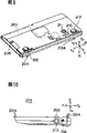
Figure 11 A and Figure 11 B are the synoptic diagram of disk drive unit, and it is the choosing dress component unit that is contained on the small-sized framework case;
Figure 12 is the skeleton view of CD-ROM driver element, and it is another choosing dress component unit that is contained on the small-sized framework case;
Figure 13 A and Figure 13 B are the battery component figure in the electronic apparatus system;
Figure 14 is the synoptic diagram of battery component groove in the electronic apparatus system;
Figure 15 has represented the synoptic diagram that battery component inserts and takes out from the battery component groove;
Figure 16 has represented the synoptic diagram that small-sized framework case adds and takes from notebook computer;
Figure 17 is the block scheme of electronic apparatus system essential part;
Figure 18 is the process flow diagram of the performed control and treatment of the control module of explanation small-sized framework case when small-sized framework case is attached on the notebook computer PC of duration of work;
Figure 19 is the process flow diagram of the control and treatment that illustrated that the control module of notebook computer PC when the notebook computer PC that is attached to duration of work when small-sized framework case goes up is performed;
Figure 20 is the process flow diagram that has illustrated when the performed control and treatment of small-sized framework case control module of small-sized framework case when the notebook computer PC of duration of work takes;
Figure 21 is the process flow diagram that has illustrated when the performed control and treatment of the control module of small-sized framework case notebook computer PC when the notebook computer PC of duration of work takes;
Figure 22 is the synoptic diagram of the connection status transition of explanation electronic apparatus system;
Figure 23 is the block scheme of the control module of notebook computer PC in the electronic apparatus system;
Figure 24 is the block scheme of connection request generation unit in the electronic apparatus system;
Figure 25 is a block scheme of removing the connection request generation unit in the electronic apparatus system;
Figure 26 has illustrated the bus connection control signal that is produced in the electronic apparatus system;
Figure 27 A and Figure 27 B are that the sequential chart of the operation of electronic apparatus system when the bus connection control signal is produced is described;
Figure 28 is a circuit diagram of removing the control module that connects the LED indicator in the electronic apparatus system.
Embodiment
Now, the preferred embodiments of the present invention are described with reference to the accompanying drawings.
Fig. 2 represents to embody the structure of electronic apparatus system of the present invention.
As shown in Figure 2, electronic apparatus system 100 generally speaking has a notebook personal computer 101, one expansions, 103, one small-sized framework cases 104 of 102, one built-in battery components of platform and a disk drive unit 105 in the present embodiment.Expansion platform 102 constitutes the docking station that can pluck formula on function expanding device of the present invention.Small-sized framework case 104 constitutes another removable docking station on function expanding device of the present invention.Battery component 103 comprises first battery and second battery.Disk drive unit 105 is connected with notebook computer PC101 is outside.
In the electronic apparatus system 100 of Fig. 2, the keyboard 108 of 107, one ten keys of 106, one printers of a color CRT (cathode-ray tube (CRT)) display and a Genius mouse 109 can be connected with notebook computer PC 101 outsides.Further, the PC card of the various PCMCIA of meeting (personal computer memory card international association) standard can be connected with notebook computer PC 101 outsides.The above-mentioned PC card of mentioning comprises SCSI (small computer system interface) card 110, IC (integrated circuit) storage card 111 and LAN (LAN (Local Area Network)) card 112.
Fig. 3 has represented the notebook computer PC101 in the electronic apparatus system 100.Fig. 4 A represents the left side of notebook computer PC 101, and Fig. 4 B represents the right side of notebook computer PC 101.Fig. 5 A represents the rear portion of notebook computer PC 101, and Fig. 5 B represents the bottom of notebook computer PC 101.
Notebook computer PC 101 in the electronic apparatus system 100 of present description present embodiment.
Notebook computer PC 101 has a host PC 113 and a display part 114 usually.Display part 114 rotatably is supported on the host PC 113.Display part 114 can rotate on the direction of the arrow D1 of Fig. 3 and D2 indication on the host PC 113.When the user carried notebook computer PC 101, display part 114 rotated with the D1 direction on host PC 113.Host PC 113 is shown part 114 fully and covers, and they are placed on the flat state shown in Fig. 4 B.
When the user used notebook computer PC 101, display part 114 rotated with the D2 direction on host PC 113.The inside surface of host PC 113 and display part 114 do not cover, and shown in Fig. 4 A, notebook computer PC 101 can operate under this state.
When notebook computer PC 101 was placed on state shown in Figure 3, the index device 116 on keyboard 115 and host PC 113 tops was not covered.During this computer of Operational Note PC 101, the user can utilize keyboard 115 to notebook computer PC 101 input commands and data, can utilize index device 116 moving cursor " P " on the display monitor central monitoring system of display part 114 simultaneously.On the back location at the top of host PC 113, a status indicators 117 is arranged.This status indicators 117 provides the indication of notebook computer PC 101 modes of operation.
Shown in Fig. 4 A, a power switch 118 is arranged in the left side of host PC 113.When power switch 118 was opened or shut, the operation of notebook computer PC 101 just began or stops.
Shown in Fig. 4 B, there are 119, one of volume controls wear receiver J-Horner 120, pickup socket 121, Line 122, theftproof lock 123, modular connector 124, PC kayser 125, a PC draw-in groove 126 and a PC card ejector knob 127 on the right side of host PC 113.
Shown in Fig. 5 A, an infrared communication hole 128, USB (USB (universal serial bus)) connector 129, extended keyboard/mouse connector 130, floppy disk connector 131, serial port connector 132, parallel port connector 133, CRT interface connector 134, direct current input (DC-IN) connector 135 and an expansion connector lid 136 are arranged in the back of host PC 113.
Infrared communication hole 128 provides finishes the needed interface of infrared communication.The external unit (not shown) that meets USB (USB (universal serial bus)) standard links to each other with USB connector 129.The keyboard 108 of ten keys or Genius mouse 109 link to each other with extended keyboard/mouse connector 130.Disk drive unit 105 links to each other with disk drive connector 131.The external unit (not shown) that meets the RS-232C standard interface links to each other with serial port connector 132.Printer 107 grades link to each other with parallel port connector 133.Color CRT display 106 links to each other with CRT interface connector 134.Provide the AC adapter (not shown) of power supply to link to each other from the outside to notebook computer PC 101 with DC-IN connector 135.When the user carried notebook computer PC 101, expansion connector lid 136 connectors for host PC 113 backs provided protection.
Shown in Fig. 5 B, an expanding element connector 137, expansion RAM (random access memory) groove 138,139, unlock button of built-in battery component lock 140, a built-in battery component groove 141 and a built-in hard drive tank 142 are arranged in the bottom of notebook computer PC 101.
Expansion platform 102 links to each other with expanding element connector 137 with small-sized framework case 104.Expansion RAM module (not shown) is inserted in the expansion RAM groove 138.The effect of battery component lock 139 is when battery component 103 inserts in the battery component groove 141 battery component 103 to be locked in the battery component groove 141.The effect of unlock button 140 then is that battery component 103 is unlocked.Battery component 103 is inserted in the battery component groove 141.Built-in harddisk driving unit 143 is inserted in the hard drive groove 142.
Further, as shown in Figure 3, LCD 144 is arranged on the inside surface of display part 114, image just shows on LCD 144.Notebook computer PC 101 comprises CPU, RAM, ROM interface circuit and telecommunication circuit, and they are combined in the host PC 113 and notebook computer PC 101 fulfillment information are handled.
Fig. 6 has represented the expansion platform 102 in the electronic apparatus system 100 of present embodiment.Fig. 7 has represented the rear portion of expansion platform 102 in the electronic apparatus system 100.
Expansion platform 102 in the electronic apparatus system 100 of present embodiment is described now.
As shown in Figure 6, there are on the platform 102 a built-in battery component groove 145,146, connector 147 of built-in battery component lock, 148, CD-ROM drive of connector lock 149, CD-ROM ejector knob 150, button release 151, release to enable lamp 152, floppy disk 153, floppy disk ejector knob 154, a PC draw-in groove 155 and a release lever 156 in expansion.
Battery component 103 is inserted in the battery component groove 145.Battery component groove 145 is used to make battery component 103 to be contained in expansion platform 102, and battery component 103 is to expansion platform 102 and notebook computer PC101 power supply.The effect of battery component lock 146 is that battery component 103 is locked in the battery component groove 145.Connector 147 links to each other with expanding element connector 137 on host PC 113 bottoms, makes expansion platform 102 be connected to each other with host PC 113.Connector lock 148 falls in part 209 (Fig. 5 B) wringing fit, feasible expansion platform 102 and 113 mechanical linking to each other of host PC with host PC 113 bottoms.CD-ROM 157 is inserted in the CD-ROM drive 149.The effect of CD-ROM drive 149 is to read information from CD-ROM 157.The effect of CD-ROM ejector knob 150 is that CD-ROM 157 is ejected from CD-ROM drive 149.The effect of button release 151 is to discharge expansion platform 102 from notebook computer PC 101.Release enables lamp 152 and is made up of LED (light emitting diode).When being set at, notebook computer PC 101 discharges under expansion platform 102 situation about can remove that to enable lamp 152 bright from notebook computer PC 101.Diskette 1 58 is inserted in the floppy disk 153, and the effect of floppy disk 153 is sense informations or information write diskette 1 58 in the diskette 1 58.The effect of floppy disk ejector knob 154 is that diskette 1 58 is ejected from floppy disk 153.PC card 159 is inserted in the PC draw-in groove 155.Before expansion platform 102 discharges from notebook computer PC 101, spur release lever 156 by the user.The effect of release lever 156 is the mechanical connections that discharge between notebook computer PC 101 and the expansion platform 102.
As shown in Figure 7, there are the fastening lock of a theftproof lock 160,161, LAN connector 162, USB connector 163, extended keyboard connector 164, mouse connector 165, serial port connector 166, voice output terminal 167, video output terminal 168, parallel port connector 169, CRT connector 170, direct current input connector 171 and some air vents 172 in expansion rear portion of platform 102 and side.
An antitheft cable (not shown) links to each other with theftproof lock 160.The effect of firm lock 161 is with the be connected pinning of antitheft cable with theftproof lock 160 when antitheft cable is fixed on theftproof lock 160.LAN cable (not shown) links to each other with LAN connector 162.The external unit (not shown) that meets the USB standard links to each other with USB connector 163.Ten keyboard 108 links to each other with extended keyboard connector 164.Mouse 109 links to each other with mouse connector 165.Having the external unit (not shown) that meets the RS-232C standard interface links to each other with serial port connector 166.Loudspeaker (not shown) or the like links to each other with voice output terminal 167.Voice signal is from 167 outputs of voice output terminal.Video board (not shown) or the like links to each other with video output terminal 168.Vision signal is from video output terminal 168 outputs.Printer with in parallel mouthful or the like links to each other with parallel port connector 169.CRT monitor 106 links to each other with CRT connector 170.AC adapter (not shown) from from the outside to 102 power supplies of expansion platform links to each other with direct current input connector 171.The effect of air vent 172 is that the air of cyclic extensions platform 102 inside is so that the inside of platform 102 is expanded in cooling.
When AC adapter linked to each other with expansion platform 102, power supply can be supplied with expansion platform 102 by AC adapter from the outside.When battery component 103 inserts battery component groove 145, can supply with expansion platform 102 from the electric energy of battery component 103.In addition, the battery component 103 of insertion battery component groove 145 can be recharged by the power supply that AC adapter provides.
Fig. 8 represents the small-sized framework case 104 in the electronic apparatus system 100.Fig. 9 shows the rear portion of the small-sized framework case 104 in the electronic apparatus system 100.Figure 10 shows the side of the small-sized framework case 104 in the electronic apparatus system 100.
In Fig. 8, Fig. 9 and Figure 10, the left that arrow X1 represents notebook computer PC 101 to, arrow X2 represents the right of notebook computer PC 101, the rear that arrow Y1 represents notebook computer PC 101 to, the place ahead that arrow Y2 represents notebook computer PC 101 to, arrow Z1 represents the last direction of notebook computer PC 101, and arrow Z2 represents the following direction of notebook computer PC 101.
Small-sized framework case 104 in the electronic apparatus system 100 of present description present embodiment.
The length of small-sized framework case 104 is " A1 ", suitable with the length " A2 " of notebook computer PC 101, width is " B1 ", approaches half of width " B2 " of notebook computer PC 101, highly be " C1 ", suitable with the height " C2 " of notebook computer PC 101.Small-sized framework case 104 is very little dimensionally, and half that approaches notebook computer PC 101 is so big.Small-sized framework case 104 is planar rectangular patterns.Additional have the notebook computer PC 101 of small-sized framework case 104 to carry easily.
As shown in Figure 8, small-sized framework case 104 has 202, one connectors 203 of 201, one battery component grooves of a telescopic backboard and lug 204 usually.Telescopic backboard 201 comprises an insertion opening 205 in small-sized framework case 104 left sides.Choosing dress component unit such as disk drive unit or CD-ROM driver element insert opening 205 by this and insert telescopic backboard 201, and the component unit that is inserted provides notebook computer PC 101 expanded functions.The disk drive unit and the CD-ROM driver element that provide as the dress of the choosing on small-sized framework case 104 component unit will be described later.
When small-sized framework case 104 was attached to notebook computer PC 101, the connector 203 on small-sized framework case 104 tops linked to each other with the connector 137 of notebook computer PC 101 bottoms.Small-sized framework case 104 is electrically connected by making connector 203 and being connected of connector 137 choosing dress component unit and notebook computer PC 101.Two lugs 204 on small-sized framework case 104 tops and part 209 wringing fits of the depression of notebook computer PC 101 bottoms.Because lug 204 is connected with sunk part 209, small-sized bottom board unit 104 just links to each other with notebook computer PC 101 machineries.
As shown in Figure 9, an operating knob 210 that meshes with lug is arranged in small-sized framework case 104 bottoms.When the user depressed this operating knob 210, two lugs of small-sized framework case 104 just discharged from the recess 209 of notebook computer PC 101.Therefore, wish that with small-sized framework case 104 user just depresses this operating knob 210 when notebook computer PC 101 removes as the user.
There is a locking bar 211 small-sized framework case 104 bottoms near the place of operating knob 210.The user handles locking bar 211 and puts so that operating knob 210 is locked in the of the lock bit of it.The effect of locking bar 211 is that small-sized framework case 104 removes from notebook computer PC 101 mistakes when preventing that user mistake from bumping operating knob 210.
Having a pair of leg 212, this leg 212 rotatably to be supported in the bottom of small-sized framework case 104 makes leg 212 to rotate between advanced position and cocked position on the hinge.When the leg 212 on small-sized framework case 104 bottoms was set at cocked position, the keyboard 115 on the inside surface of notebook computer PC101 can be in the state of an inclination.
As shown in Figure 10, have one to remove connection request button 213 and remove link indicator 214 in the side of small-sized framework case 104.Removing link indicator 214 is made up of LED (light emitting diode).When the user depresses this releasing connection request button 213, this releasing connection request button 213 role at that time is to activate to remove connection request generation unit (will describe afterwards), so that request notebook computer PC 101 allows small-sized framework case 104 to break away from from this notebook computer PC 101.Remove link indicator 214 and open, an indication is provided: notebook computer PC 101 allows small-sized framework case 104 to break away from from notebook computer PC 101.
Choosing dress component unit-disk drive unit 215 that Figure 11 A and Figure 11 B represent to be installed on the small-sized framework case 104.Figure 11 A has represented the bottom of disk drive unit 215, and Figure 11 B has represented the top of disk drive unit 215.
Figure 12 has represented to be installed in another choosing dress component unit-CD-ROM driver element 218 on the small-sized framework case 104.
CD-ROM driver element 218 inserts telescopic backboard 201 by the socket 205 of small-sized framework case 104 on the X1 direction.The CD-ROM driving 218 of being inserted provides the expanded function of a notebook computer PC 101.As shown in Figure 12, this CD-ROM driver element 218 comprises a connector 219 and a CD-ROM insertion portion 220.When this CD-ROM driver element 218 is installed on the telescopic backboard 201 of small-sized framework case 104, connector 219 links to each other with connector 216A, so CD-ROM driver element 218 interconnects because of connector 219 and being connected of connector 216A with notebook computer PC 101.Furtherly, when CD-ROM driver element 218 was contained on the telescopic backboard 201, the insertion portion 220 of this CD-ROM was located on the socket 205 of small-sized framework case 104.The CD-ROM (not shown) can easily be inserted or take out from CD-ROM driver element 218 by CD-ROM insertion portion 220.
Figure 13 A and Figure 13 B have represented the battery component 103 in the electronic apparatus system 100.In Figure 13 A, from lower position battery component 103.In Figure 13 B, battery component 103 is reversed, from higher position battery component 103.
Just as shown in FIG. 13A, battery component 103 comprises a pair of recess 175 and 176 in battery component 103 fronts.Shown in Figure 13 B, battery component 103 comprises a pair of recess 177 and 178 and recesses 179 in battery component 103 back.The effect of recess 175 to 179 is to make a scouring machine tool in the relevant battery component groove 141,145 or 202 of battery component 103 and notebook computer PC 101, expansion platform 102 and small-sized framework case 104 continuous.
Figure 14 has represented the battery component groove in the electronic apparatus system 100.
In the electronic apparatus system 100 of present embodiment, the battery component groove 141 of notebook computer PC 101, the battery component groove 145 of expansion platform 102 and the battery component groove 202 of small-sized framework case 104 are being identical in shape.Battery component 103 can insert in arbitrary groove in the battery component groove 141,145,202.For convenience's sake, take the representative of battery component groove 141 now, will be described as battery component groove 141,145 and 202.
As shown in Figure 14, battery component groove 141 comprises a recess 180, contact terminal 181, coupling part 182 and battery component lock 139.Recess 180 can be arranged on the top or the bottom of one of notebook computer PC 101, expansion platform 102 and small-sized framework case 104.The structure of recess 180 is identical with the structure of battery component 103.When battery component 103 inserted recesses 180, contact terminal 181 just was electrically connected with the terminal 174 of battery component 103.When battery component 103 inserts recesses 180, coupling part 182 just with recess 175~179 wringing fits of battery component 103.Battery component lock 139 is operated by the user, and battery component lock 139 is because of being locked in battery component 103 in the battery component groove 141 coupling part 182 and being connected of recess 175~179.When the user opened battery component and locks 139, just threw off with recess 175~179 coupling part 182, so battery component 103 can spin off from battery component groove 141.
Figure 15 shows battery component 103 and inserts the situation of taking out from battery component groove 141.
As shown in Figure 15, when battery component 103 inserted battery component groove 141 with the direction shown in the arrow 183, the recess 173 of battery component 103 matched with the appropriate section of the recess 180 of battery component groove 141.With when the appropriate section of recess 180 matches, battery component 103 rotates with the direction shown in the arrow 184 at recess 173.Then, battery component 103 just inserts in the recess 180 of battery component groove 141 fully.
Figure 16 shows small-sized framework case 104 and is contained on the notebook computer PC 101 and the situation from separating.
In the electronic apparatus system 100 of present embodiment, when using, small-sized framework case 104 is contained in the bottom of notebook computer PC 101.Disk drive unit 215 or CD-ROM driver element 218 are installed on the extension frame 201 of small-sized framework case 104 as the choosing dress component unit 221 of the expanded function that notebook computer PC 101 is provided.
The feature of the electronic apparatus system 100 of present embodiment is when small-sized framework case 104 is added on the notebook computer PC 101 that is in mode of operation, and choosing dress component unit 221 (disk drive unit 215 or CD-ROM driver element 218) can be taken off from small-sized framework case 104.
When the small-sized framework case 104 that has comprised choosing dress component unit 221 (it is installed on the telescopic backboard 201) is added on the notebook computer PC 101, in the time of in the idle telescopic backboard 201 of the perhaps elected dress component unit 221 small-sized framework cases 104 of insertion (it is added on the notebook computer PC 101), small-sized framework case 104 sends a connection request to notebook computer PC 101, has choosing dress component unit 221 so notebook computer PC 101 just identifies in electronic apparatus system 100.
On the other hand, when the small-sized framework case 104 that has comprised choosing dress component unit 221 (it is installed on the telescopic backboard 201) when notebook computer PC 101 takes off, when the small-sized framework case 104 of perhaps elected dress component unit 221 on being added in notebook computer PC 101 took off, the user pressed the releasing connection request button 213 of small-sized framework case 104 sides.When releasing connection request button 213 was pressed, small-sized framework case 104 sent one to notebook computer PC 101 and removes connection request, and this releasing connection request makes notebook computer PC 101 allow choosing dress component units 221 to take off from small-sized framework case 104.The releasing that small-sized framework case 104 receives by notebook computer PC 101 outputs connects recall signal, and this releasing connection recall signal represents that notebook computer PC101 has allowed to break away from.When receiving that releasing connects recall signal, remove link indicator LED 214 and just light, provided an indication: allow choosing to adorn component unit 221 and separate from small-sized framework case 104.Therefore, when small-sized framework case 104 was added on the notebook computer PC 101 that is in mode of operation, choosing dress component unit 221 can be taken off from small-sized framework case 104.
Figure 17 is the block scheme of the essential part of electronic apparatus system 100, and it relates to small-sized framework case 104 and installs on the notebook computer PC 101 and from notebook computer PC 101 and take off.
As shown in Figure 17, the connector 137 of notebook computer PC 101 is connected to each other with the connector 203 of small-sized framework case 104, and the connector 216A of small-sized framework case 104 is connected to each other with the connector 216 (or 219) of choosing dress component unit 221.
In notebook computer PC 101, connector 137 links to each other with signal buffer 223 by PCI (peripheral component interconnect) bus 222, and signal buffer 223 links to each other with CPU 224 by pci bus 222a.Control module 225 links to each other separately with this CPU 224, signal buffer 223 and connector 137, and various control signals transmit between this control module 225 and these unit 224,223 and 137.Further, input equipment 229 links to each other with CPU 224.
When small-sized framework case 104 or expansion platform 102 is added on the notebook computer PC 101 or when small-sized framework case 104 or expansion platform 102 when notebook computer PC 101 takes off, control module 225 is carried out a control program.
In small-sized framework case 104, connector 203 links to each other with connector 216A by pci bus 226.Connector 203 also links to each other with control module 227, and control module 227 links to each other with connector 216A.Further, remove connection request button (switch) 213 and link to each other, and releasing link indicator LED (indicator) 214 links to each other with control module 227 with control module 227.
When small-sized framework case 104 install on the notebook computer PC 101 or small-sized framework case 104 when notebook computer PC 101 takes off, control module 227 is just carried out a control program.
In choosing dress component unit 221, connector 216 (or 219) is linked driver 228.It is that disk drive function or CD-ROM drive function that driver 228 provides the expanded function of notebook computer PC 101.
The control module 227 that Figure 18 has represented small-sized framework case 104 performed control program when small-sized framework case 104 is added on the notebook computer PC 101 that is in operating period.
When the connector 203 of the connector 137 of notebook computer PC 101 and small-sized framework case is connected to each other and selects dress component unit 221 to be installed in the telescopic backboard 201 of small-sized framework case 104, supply with the power supply that comes from notebook computer PC 101 control module 227 starts are resetted.As shown in Figure 18, whether control module 227 is started shooting at step S1-1 detection control module 227 and is resetted.When the result of step S1-1 is when negating, then the detection of step S1-1 repeats.As the result of step S1-1 when being sure, control module 227 just sends a connection request at step S1-2 by connector 203 and 137 control modules 225 to notebook computer PC 101.After connection request was exported to notebook computer PC 101, the control program of Figure 18 just was through with.
The control module 225 that Figure 19 has represented notebook computer PC 101 performed control program when small-sized framework case 104 is added on the notebook computer PC 101 that is in operating period.
As shown in Figure 19, whether control module 225 is received from the connection request of control module 227 at step S2-1 detection notebook computer PC 101.When the result of step S2-1 whether regularly, the detection of step S2-1 repeats.As the result of step S2-1 when being sure, control module 225 is just finished bus and is connected so that the pci bus 222a of small-sized framework case 104 is linked to each other with pci bus 226 at step S2-2 mat control signal impact damper 223.Bus is connected after step S2-2 finishes, and control module 225 makes CPU 224 identifications whether have the driver 228 of choosing dress component unit 221 at step S2-3.After step S2-3 finished driver identification, the existence that installs to the driver 228 of the choosing dress component unit 221 on the notebook computer PC 101 through small-sized framework case 104 was just discerned by the CPU 224 of notebook computer PC 101.Then, the control program of Figure 19 just is through with.
The control module 227 that Figure 20 has represented small-sized framework case 104 is at small-sized framework case 104 performed control program when the notebook computer PC 101 that is in operating period breaks away from.
When the small-sized framework case 104 that has comprised choosing dress component unit 221 (being installed on the telescopic backboard 201) when notebook computer PC 101 breaks away from, perhaps elected dress component unit 221 is when small-sized framework case 104 (being added on the notebook computer PC 101) breaks away from, and the user presses the releasing connection request button 213 of small-sized framework case 104 sides.
As shown in Figure 20, whether control module 227 is pressed by the user at step S3-1 detection releasing connection request button 213.As the result of step S3-1 when being sure, control module 227 sends one at step S3-2 and removes the control module 225 that connection request signal is given notebook computer PC 101.Otherwise the detection of step S3-1 repeats.
Remove connection request signal after step S3-2 is issued, whether control module 227 is received on small-sized framework case 104 in the releasing connection recall signal that step S3-3 detects control module 225 outputs.As the result of step S3-3 when being sure, control module 227 is opened at step S3-4 and is removed link indicator 214.Otherwise the detection of step S3-3 repeats.Be unlocked if remove link indicator 214, then just provide an indication for the user: notebook computer PC 101 allows choosing dress component unit 221 to break away from from small-sized framework case 104.
Remove link indicator 214 after step S3-4 is unlocked, whether whether control module 227 detect small-sized framework case 104 at step S3-5 and break away from from small-sized framework case 104 from notebook computer PC 101 disengagings and detection choosing dress component unit 221.Its foundation of detection of finishing breaking away from step S3-5 is: detect from notebook computer PC 101 and adorn the power supply that component unit 221 provides to control module 227 by small-sized framework case 104 to the power supply that selects dress component unit 221 to provide and by choosing.When small-sized framework case 104 when notebook computer PC 101 breaks away from, just do not supply with control module 227 from the power supply of notebook computer PC 101.Therefore, according to whether there being power supply to supply with control module 227, the disengaging detection that control module 227 just can completing steps S3-5.
When detect at step S3-5 small-sized framework case 104 from notebook computer PC 101 break away from or choosing dress component unit 221 when small-sized framework case 104 breaks away from, control module 227 is closed at step S3-6 and is removed link indicator 214.Otherwise step S3-4 and S3-5 repeat.After step S3-6 finished, the control program of Figure 20 just was through with.
The control module 225 that Figure 21 has represented notebook computer PC 101 is at small-sized framework case 104 performed control program when the notebook computer PC 101 that is in operating period breaks away from.
As shown in Figure 21, whether the releasing connection request signal that control module 225 is exported at step S4-1 detection control module 227 is received.As the result of step S4-1 when being sure, control module 225 makes CPU 224 finish the releasing linker at step S4-2.Otherwise the detection of step S4-1 repeats.CPU 224 finishes and removes during the linker, and the identification of choosing being adorned the driver 228 of component unit 221 has been cancelled.
After step S4-2 finished, whether control module 225 detected the releasing linker of being done by CPU 224 at step S4-3 and finishes.As the result of step S4-3 when being sure, control module 225 sends one at step S4-4 and removes and connect the control module 227 that recall signal is given small-sized framework case 104.Otherwise the detection of step S4-3 repeats.The releasing that sends control module 227 to connects recall signal and has indicated notebook computer PC 101 to allow small-sized framework case 104 to break away from from small-sized framework case 104 from notebook computer PC 101 disengagings or choosing dress component unit 221.
Removing the connection recall signal after step S4-4 issues control module 227, control module 225 is finished bus at step S4-5 mat control signal impact damper 223 and is broken away from, so that pci bus 222a is broken away from from the pci bus 226 of small-sized framework case 104.After step S4-5 finished, the control program of Figure 21 just was through with.
In the above-described embodiment, when small-sized framework case 104 linked to each other with the notebook computer PC 101 that is in mode of operation, choosing dress component unit 221 can be taken off from small-sized framework case 104.When the choosing in the small-sized framework case 104 dress component unit 221 desires are changed a new component unit, do not need the power switch 118 that stops the operation of notebook computer PC 101 or close notebook computer CP 101.Even the component unit that choosing dress component unit 221 is more renewed.The electronic apparatus system 100 of the foregoing description offers the enough operability of user effectively.
Figure 22 shows the transition of the connection status of electronic apparatus system 100.
The electronic apparatus system 100 of present embodiment is controlled during operation, and the transition of its connection status as shown in figure 22.The connection status of Figure 22 comprises released state S1, adds state S2, connection procedure state S3, connection status S4, remove connection procedure state S5, isolation S6, remove connection status S7 and abort state S8.Electronic apparatus system 100 is controlled during operation, is in these states (state among the S1~S8).
When electronic apparatus system 100 is in released state S1, expansion platform 102 just breaks away from from notebook computer PC 101, small-sized framework case 104 breaks away from from notebook computer PC 101, perhaps when small-sized framework case 104 was added on the notebook computer PC 101, choosing dress component unit 221 broke away from from small-sized framework case 104.
The state S2 of adding is the transition state of electronic apparatus system 100.In adding state S2, notebook computer PC 101 links to each other with expansion platform 102, but notebook computer PC 101 is connected also with the pci bus of expansion between the platform 102 and does not begin, perhaps choosing dress component unit 221 links to each other with small-sized framework case 104 on being added in notebook computer PC 101, but notebook computer PC 101 is connected also with pci bus between the small-sized framework case 104 and does not begin.
When electronic apparatus system 100 was in connection procedure state S3, notebook computer PC 101 was connected with the pci bus of expansion between the platform 102 and finishes, and perhaps notebook computer PC 101 is connected with pci bus between the small-sized framework case 104 and finishes.After the pci bus connection connected well fully, electronic apparatus system 100 just changed to connection status S4 from connection procedure state S3.Finish the software of the incident DOCKSMI# notice notebook computer PC 101 that time that pci bus connects sent by the control module 225 of notebook computer PC 101.It is to notify software that this incident DOCKSMI# is issued: the connection of pci bus has been finished.
Connection status S4 is a state of electronic apparatus system 100, in this state, expansion platform 102 was finished with being connected of notebook computer PC 101, and perhaps choosing dress component unit 221 was finished with being connected of small-sized framework case 104 on being added in notebook computer PC 101.Finishing of connecting means that pci bus connects and notifies the two all to be implemented with being connected of the software of telling notebook computer PC 101.When electronic apparatus system 100 changed to connection status S4, the resource distribution of electronic apparatus system 100 just restarted.As the result of configuration, the up-to-date equipment of linking electronic apparatus system 100 is identified so that adopt this equipment by the CPU 224 of notebook computer PC 101.
When the releasing connection request button on small-sized framework case 104 or the expansion platform 102 is pressed by the user or when the releasing connection request image on the indicating ﹠ controlling device of notebook computer PC 101 is pinned by the user, removing connection procedure at the beginning, electronic apparatus system 100 just changes to from connection status S4 and removes connection procedure state S5.This releasing connection procedure is begun by the incident UNDKREQ# that software sent of notebook computer PC 101.During removing connection procedure, interrupt request is issued the device driver of being discerned by the operating system center, and, sending the pci bus of removing connection by BIOS (Basic Input or Output System (BIOS)) and isolate request, device driver is approved after interrupt request.After the releasing connection procedure was finished, electronic apparatus system 100 just changed to isolation S6 from removing connection procedure state S5.
When electronic apparatus system 100 was in isolation S6, the pci bus isolation between notebook computer PC 101 and the expansion platform 102 was finished, and perhaps the isolation of the pci bus between notebook computer PC 101 and the small-sized framework case 104 is finished.The pci bus isolation is sent the software that an incident UNDKSMI# removes to notify notebook computer PC 101 after finishing: remove to connect and finishes.After the notice that releasing connects was finished, electronic apparatus system 100 just changed to from isolation S6 and removes connection status S7.
When electronic apparatus system 100 is in releasing connection status S7, pci bus isolation between notebook computer PC 101 and the expansion platform 102 has been finished, but expansion platform and notebook computer PC 101 also in succession, perhaps choosing dress component unit 221 is isolated with the pci bus between the small-sized framework case 104 that is added on the notebook computer PC 101 and has been finished, but choosing dress component unit 221 and small-sized framework case 104 are also ined succession.During removing connection status S7, all resources of expansion platform 102 or all resources of small-sized framework case 104 are not discerned by notebook computer PC 101.When electronic apparatus system 100 is in releasing connection status S7, removes link indicator LED and lighted.
When expansion platform 102 from notebook computer PC 101 break away from or when small-sized framework case 104 when notebook computer PC 101 breaks away from, electronic apparatus system 100 just changes to released state S1 from releasing connection status S7.When electronic apparatus system 100 was in releasing connection status S7 and sends an abort commands, electronic apparatus system 100 just changed to abort state S8.
When electronic apparatus system 100 was in abort state S8, power supply did not resupply most of resources of the expansion platform 102 that links to each other with notebook computer PC 101, and perhaps power supply does not resupply most of resources of the small-sized framework case 104 that links to each other with notebook computer PC 101.During abort state, power supply is only supplied with connection state that part of that expansion platform 102 or small-sized framework case 104 needs monitoring electronic apparatus systems 100.
When electronic apparatus system 100 when connection status S4 changes to abort state S8, pci bus between notebook computer PC 101 and the expansion platform 102 or the pci bus between choosing dress component unit 221 and the small-sized framework case 104 are isolated automatically.In order to allow electronic apparatus system 100 to change to connection status S4, need finish between notebook computer PC 101 and expansion platform 102 that pci bus is connected or between component unit 221 and small-sized framework case 104 are adorned in choosing, finish pci bus and be connected from abort state S8.Therefore, electronic apparatus system 100 changes to connection status S4 from abort state S8 and must pass through connection procedure state S3.
When electronic apparatus system 100 was in releasing connection status S7 and sends an abort commands, electronic apparatus system 100 just changed to abort state S8.Furtherly, when electronic apparatus system 100 was in abort state S8 and finish an operation that restarts, electronic apparatus system 100 just changed to and adds state S2.At this moment, send the software that an incident DKSITSM# removes to notify notebook computer PC 101: connect and finished.
Since incident (or interrupt request) DKSITSMI#, UNDKREQ#, the appearance of any one incident among DOCKSMI# or the UNDKSMI#, the electronic apparatus system 100 of present embodiment just changes to another kind of connection state from a kind of connection state during operation.
Incident DKSITSMI# is issued the software of notifying notebook computer PC 101: connect and finish.For example, when expansion platform 102 when being added to notebook computer PC 101 or elected dress component unit 221 when being added to the small-sized framework case 104 that links to each other with notebook computer PC 101, just notify the software of notebook computer PC 101: expansion platform 102 has added or has selected and adorned component unit 221 and added.The transition of the connection state of electronic apparatus system 100 are caused by incident DKSITSMI# as above-mentioned.
The incident DOCKSMI# of sending removes to notify the software of notebook computer PC 101: the pci bus between the pci bus between expansion platform 102 and the notebook computer PC 101 or the choosing of small-sized framework case 104 dress component unit 221 and the notebook computer PC 101 is connected to each other.The transition of the connection state of electronic apparatus system 100 are caused by incident DOCKSMI# as above-mentioned.
The incident UNDKSMI# of sending removes to notify the software of notebook computer PC 101: the pci bus between the pci bus between expansion platform 102 and the notebook computer PC 101 or the choosing of small-sized framework case 104 dress component unit 221 and the notebook computer PC 101 is thrown off mutually.The transition of the connection state of electronic apparatus system 100 are caused by incident UNDKSMI# as above-mentioned.
Incident DKSITSMI#, UNDKREQ#, each incident among DOCKSMI# and the UNDKSMI# is when it sends, and the interrupt request singal of incident sends to the connection controller 302 (will describe later on) of notebook computer PC 101 respectively.
Figure 23 has represented the structure of the control module 225 of notebook computer PC 101 in the electronic apparatus system 100 of present embodiment.
As shown in Figure 23, the control module 225 of notebook computer PC 101 generally has 302, one order of connection devices 303 of a connection controller and an announcing circuit 304.The control module 225 of notebook computer PC 101 is considered the connecting circuit 301 among Figure 23 among Figure 17.The CPU 224 of notebook computer PC 101 is considered the CPU 305 among Figure 23 among Figure 17.
In the connecting circuit 301 of Figure 23, incident DKSITSMI#, UNDKREQ#, the polling of DOCKSMI# and UNDKSMI# finish in the time interval of 10ms by being connected controller 302.Incident DKSITSMI#, UNDKREQ#, the interrupt request singal of one of DOCKSMI# and UNDKSMI# is each when detected, connects controller 302 and makes look-at-me of announcing circuit 304 outputs give the software of CPU 305 handled notebook computer PC101.
According to the instruction of CPU 305 output, order of connection device 303 starts, and the interrupt request singal of incident DOCKSMI# and one of UNDKSMI# exported to is connected controller 302.Therefore, the transition of the connection state of electronic apparatus system 100 cause by connecting notification event DOCKSMI# or removing connection notification event UNDKSMI# as above-mentioned.
Be that response connects the request that controller 302 is exported, announcing circuit 304 is delivered to software by CPU 305 handled notebook computer PC 101 with a look-at-me.The cause of the interruption that provides in order to detect, this software are sent an inquiry command and are given the value of returning that connects controller 302 and receive an inquiry command from connection controller 302.When with incident DKSITSMI#, UNDKREQ#, when corresponding time value of the incident of one of DOCKSMI# and UNDKSMI# was detected, the cause of the interruption that is provided by announcing circuit 304 just can be discerned by the software of notebook computer PC 101.
After the finishing dealing with of this incident, announcing circuit 304 provides a state clear signal CLRFLG# to expansion platform 102 or offer the control module 227 of small-sized framework case 104.The state clear signal of providing is in order to remove the state-event of expansion platform 102 or small-sized framework case 104.The control module 227 of small-sized framework case 104 has been cancelled the breech lock of incident DKSITSMI# and UNDKREQ# and has been allowed to receive next the interruption.
When expansion platform 102 is added on the notebook computer PC 101, confirm that internal signal CD1# and CD2# that expansion platform 102 links to each other with notebook computer PC 101 are assert, and, export to the interrupt request singal DKSITSMI# that connects controller 302 and stablize the low state that is placed at internal signal CD1# and CD2#.When notebook computer PC 101 was in off status, sleep state or opens state, the output of this interrupt request singal DKSITSMI# had just been finished.When the power switch of notebook computer PC 101 is opened, be detected by the low state of the interrupt request singal DKSITSMI# that exported of expansion platform 102.This connection controller 302 can receive the low state interrupt request signal DKSITSMI# that expansion platform 102 is exported.
In the time of on the elected dress small-sized framework case 104 that component unit 221 is added to notebook computer PC 101 links to each other, confirm that internal signal CD1# and CD2# that small-sized framework case 104 links to each other with notebook computer PC 101 are assert, confirm that internal signal BAYCD1# and BAYCD2# that choosing dress component unit 221 links to each other with telescopic backboard 201 are assert, and, the interrupt request singal DKSITSMI# that exports to connection controller 302 is at internal signal CD1#, CD2#, BAYCD1# and BAYCD2# stablize the low state that is placed on.
Place high state under the interrupt request singal DKSITSMI# normal condition.When notebook computer PC 101 is in off status or sleep state, exports to the interrupt request singal DKSITSMI# that connects controller 302 deadlock (latch-up) may take place.With a diode finish interrupt request singal DKSITSMI# to the obstruction of notebook computer PC 101 so that avoid deadlock.Utilize a power supply that equates with the power supply that interrupts detecting unit taking to draw (pulling-up) treatment measures on the side of notebook computer PC 101.
The software detection of notebook computer PC 101 is after the finishing dealing with of look-at-me and incident, and the announcing circuit 304 of notebook computer PC 101 provides a state clear signal CLRFLG# control module 227 to small-sized framework case 104.It is in order to remove the state-event of small-sized framework case 104 that state clear signal CLRFLG# is provided.The control module 227 of small-sized framework case 104 has been cancelled the breech lock of incident DKSITSMI# and has been allowed to receive next the interruption.
Figure 24 has represented the connection request generation unit 400 in electronic apparatus system 100.Give notebook computer PC 101 so that permission choosing dress component unit 221 is added on the small-sized framework case 104 or allows expansion platform 102 to be added on the notebook computer PC 101 at these connection request generation unit 400 connection requests of output (or interrupt request singal DKSITSMI#) on the small-sized framework case 104.
The two is formed the connection request generation unit 400 of present embodiment by first control circuit 401 (providing in the control module 227 of small-sized framework case 104) and second control circuit 402 (providing in the control module 225 of notebook computer PC 101).
As shown in Figure 24, first control circuit 401 comprises: first logical circuit 411, the second logical circuits 412, bistable circuit 413 and the diode 414.When removing the signal LEDON# that places low state when link indicator LED lights and when power supply correctly offers small-sized framework case 104, placing the power supply signal POWERGOOD of high state to deliver to first logical circuit 411 from the internal circuit of small-sized framework case 104.Signal SUSTAT# delivers to first logical circuit 411 from notebook computer PC 101.First logical circuit 411 is finished a logical operation:
(signal LEDON#+ signal POWERGOOD) signal SUSTAT#,
Export a signal PRI# who presets delivers to bistable circuit 413 as the result of logical operation input end FF simultaneously.
Signal SUSTAT# and state clear signal CLRFLG# deliver to second logical circuit 412 from notebook computer PC 101.Second logical circuit 412 is finished a logical operation:
(signal SUSTAT#+ signal CLRFLG#) exports a clock signal is delivered to bistable circuit 413 as the result of logical operation input end of clock CK simultaneously.The data input pin D of bistable circuit 413 always remains on high state.
Connection request (or interrupt request singal DKSITSMI#) is exported to the second control circuit 402 of notebook computer PC 101 from the inverse output terminal Q# of bistable circuit 413.As shown in Figure 24, interrupt request singal DKSITSMI# offers the second control circuit 402 of notebook computer PC 101 by diode 414.The effect of diode 414 is to finish the obstruction of interrupt request singal DKSITSMI# to notebook computer PC 101 when notebook computer PC 101 places off status or sleep state.The deadlock of bistable circuit 413 is avoided by diode 414.
As shown in Figure 24, second control circuit 402 comprises: interrupt detecting unit 421, resistance 422 and switch 423.The appearance of the connection request (or interrupt request singal DKSITSMI#) that is provided by first control circuit 401 when the interrupt request singal DKSITSMI# that interrupting detecting unit 421 detections is provided places the state of hanging down.Resistance 422 is connected between the signal path of the power supply that interrupts detecting unit 412 and interrupt request singal DKSITSMI#.The effect of circuit 422 is to draw on the signal path with interrupt request singal DKSITSMI#.This diode 414 and resistance 422 prevent bistable state 413 deadlock when notebook computer PC 101 places off status or sleep state.Switch 423 connects or throws off and open or close according to pci bus, and is controlled on the signal path to interrupting the connection request (or interrupt request singal DKSITSMI#) that detecting unit 421 provides.
In the connection request generation unit 400 of Figure 24, when expansion platform 102 is added on the notebook computer PC 101, confirm that internal signal CD1# and CD2# that expansion platform 102 links to each other with notebook computer PC 101 are assert, and the interrupt request singal DKSITSMI# that exports to the control module 225 of notebook computer PC 101 becomes at internal signal CD1# and CD2# and is placed in low state after stable.When notebook computer PC 101 places off status, sleep state or opens state, first control circuit 401 this interrupt request singal of output DKSITSMI#.When opening the power switch of notebook computer PC 101, detect by interrupting detecting unit 421 by the low state of the interrupt request singal DKSITSMI# of expansion platform 102 output.Connect controller 302 and can receive the low state interrupt request signal DKSITSMI# that is exported by expansion platform 102.
In the time of on the elected dress small-sized framework case 104 that component unit 221 is added to notebook computer PC 101 links to each other, confirm that internal signal CD1# and CD2# that small-sized framework case 104 links to each other with notebook computer PC 101 are assert, confirm that internal signal BAYCD1# and BAYCD2# that choosing dress component unit 221 links to each other with telescopic backboard 201 are assert, and, the interrupt request singal DKSITSMI# of control module 225 that exports to notebook computer PC 101 is at internal signal CD1#, it is stable to be placed on low state that CD2#, BAYCD1# and BAYCD2# become.When notebook computer PC 101 places off status, sleep state or when opening state, first control circuit 401 is exported to this interrupt request singal DKSITSMI# and interrupted detecting unit 421.
The releasing connection processing of electronic apparatus system 100 when the releasing connection request button on small-sized framework case 104 or the expansion platform 102 is pressed by the user or when the releasing connection request image on notebook computer PC 101 indicating ﹠ controlling devices is pinned by the user then will be described below.
In the electronic apparatus system 100 of present embodiment, when the releasing connection request button on the platform 102 is pressed by the user when small-sized framework case 104 or expansion or when the releasing connection request image on notebook computer PC 101 indicating ﹠ controlling devices was pinned by the user, the software of notebook computer PC 101 sent this interrupt request singal UNDKREQ#.The interrupt request singal UNDXREQ# that software sent of notebook computer PC 101 has started the releasing connection processing.After the releasing connection processing was finished, electronic apparatus system 100 changed to isolation S6 from removing connection processing state S5.
Interrupt request singal UNDKREQ# is identified as when being added on the notebook computer PC 101 low at small-sized framework case 104 or expansion platform 102, and notebook computer PC 101 places out state.But, when releasing link indicator LED 214 is lighted after the releasing connection processing is finished, press releasing connection request button or pin releasing connection request image all inoperative.
Figure 25 represents the releasing connection request generation unit 500 in the electronic apparatus system 100.Exporting releasing connection requests (interrupt request singal UNDKREQ#) at the releasing connection request generation unit 500 of small-sized framework case 104 or expansion platform 102 sides (or in the side that connects platform) breaks away from from notebook computer PC 101 from small-sized framework case 104 disengagings or permission expansion platform 102 so that allow choosing to adorn component unit 221 to notebook computer PC 101.
The two is formed by first control circuit 501 and second control circuit 502 to remove connection request generation unit 500 in the present embodiment, first control circuit 501 provides in the control module 227 of small-sized framework case 104, and second control circuit 502 provides in the control module 225 of notebook computer PC 101.
As shown in Figure 25, first control circuit 501 comprises: 512, one of 511, one logical circuits of reset circuit of starting shooting are one by one removed 514, one of 513, one not gates of connection request button and 515, one bistable states 516 of door and a diode 517.
Start reset circuit 511 (or provides in the power circuit of expansion platform 102 at small-sized framework case 104.When the power supply from battery component 103 or AC adapter was sent to small-sized framework case 104 (or expansion platform 102), start reset circuit 511 placed out state.The start reset signal of start reset circuit 511 outputs is sent to logical circuit 512, and the state clear signal CLRFLG# that is exported by notebook computer PC101 is sent to logical circuit 512.This logical circuit 512 finish start reset signal and state clear signal CLRFLG# with operation and export input end FF that a reset signal RST# gives bistable state 516 with as the result who should and operate.
Remove the releasing connection request button 513 that connection request button 213 is considered among Figure 25 among Figure 10.For the permission that obtains to select dress component unit 221 to break away from from small-sized framework case 104, the user presses and removes connection request button 513.Removing the signal of connection request button 513 outputs delivers to and door 515 by not gate 514.When lighting, link indicator LED place the signal LEDON# of low state to be sent to and door 515 when removing.When releasing link indicator LED closed, signal LEDON# placed high state.
With door 515 finish on not gate 514 output terminals remove connection request signal and LEDON# signal with operation and export the input end of clock CK of a clock signal to bistable state 516.The data input pin D of bistable state 516 always remains on high state.
Remove connection request (or interrupt request singal UNDKREQ#) and export to the second control circuit 502 of notebook computer PC 101 from the inverse output terminal Q# of bistable state 516.As shown in Figure 25, interrupt request singal UNDKREQ# delivers to the second control circuit 502 of notebook computer PC 101 by diode 517.The effect of diode 517 is to finish the obstruction of interrupt request singal UNDKREQ# to notebook computer PC 101 when notebook computer PC 101 places off status or sleep state.The deadlock of bistable state 516 is avoided by diode 517.
As shown in Figure 25, second control circuit 502 comprises: interrupt detecting unit 521, resistance 522 and a switch 523.Interrupting detecting unit 521 is to be driven by the electric power that power supply provides, the appearance of the releasing connection request (or interrupt request singal UNDKREQ#) that first control circuit 501 was provided when its detected and the interrupt request singal UNDKREQ# that is provided is provided places low state.Resistance 522 is connected between the signal path of the power supply that interrupts detecting unit 512 and interrupt request singal UNDKREQ#.Bistable state 516 deadlocks when diode 517 and resistance 522 prevent that notebook computer PC 101 from placing off status or sleep state.Switch 523 connects or throws off and open or close according to pci bus, and it is controlled at removes connection request (or interrupt request singal UNDKREQ#) to providing of detecting unit 521 is provided on the signal path.
In the releasing connection request generation unit 500 of Figure 25, when the releasing connection request button on the platform 102 is pressed by the user when small-sized framework case 104 or expansion or when the releasing connection request image on notebook computer PC 101 indicating ﹠ controlling devices is pinned by the user, remove connection request (interrupt request singal UNDKREQ#) and export to notebook computer PC 101 so that allow choosing dress component unit 221 to break away from or allow expansion platform 102 from notebook computer PC 101 disengagings from small-sized framework case 104.
Figure 26 represents the bus connection control signal QPCIEN# of generation in the electronic apparatus system 100.Figure 27 A and Figure 27 B are time diagrams, the operation of electronic apparatus system 100 when setting forth bus connection control signal QPCIEN# generation.Figure 27 A represents the high/low state of bus connection control signal QPCIEN#, and Figure 27 B represents the pci bus connection status of electronic apparatus system 100.
As shown in Figure 26, the order of connection device 701 that is provided in the control module 225 of bus connection control signal QPCIEN# by notebook computer PC101 produces.The bus connection control signal QPCIEN# of order of connection device 701 output deliver to switch (Q-SW) 702 and interrupt detecting unit 706 the two.
Switch 702 provides on the pci bus 703 of notebook computer PC 101, and switch 702 is linked main frame side connector 704 (for example, being the connector 137 of notebook computer PC101) by pci bus 703.Switch 702 opens or closes according to the height state of the bus connection control signal QPCIEN# of order of connection device 701 outputs.When bus connection control signal QPCIEN# places high state, switch 702 leaves, so that through main frame side connector 704 with to be connected pci bus 703 that platform side connector 704 makes notebook computer PC 101 continuous with the pci bus 705 that is connected platform (small-sized framework case 104 or expand platform 102).Shown in Figure 27 B, the pci bus connection is based upon under this situation.When bus connection control signal QPCIEN# placed the state of hanging down, switch 702 closed, so that the pci bus 703 of notebook computer PC 101 is broken away from from the pci bus 705 that connects platform (small-sized framework case 104 or expansion platform 102).Shown in Figure 27 B, the pci bus isolation is based upon under this situation.
As mentioned above, the bus connection control signal QPCIEN# of order of connection device 701 outputs delivers to and interrupts detecting unit 706.Interrupt the rising edge of detecting unit 706 testbus connection control signal QPCIEN#, and export a connection request and be used to carry out connection processing from low state to high state.Interrupt the negative edge of detecting unit 706 testbus connection control signal QPCIEN#, and export one and remove connection request and be used for carrying out and remove connection processing from high state to low state.
To then describe below and connect the control that platform (small-sized framework case 104 or expansion platform 102) is gone up releasing link indicator LED.
Remove link indicator LED when it is lighted, provide an indication: notebook computer PC 101 permission choosing dress component units 221 break away from or allow to expand platform 102 from small-sized framework case 104 and break away from from notebook computer PC 101.Remove link indicator LED by light be pci bus between small-sized framework case 104 and notebook computer PC 101 isolate or expansion platform 102 and notebook computer PC 101 between the pci bus isolation finish after.Remove link indicator LED be closed be choosing dress component unit 221 from the small-sized end mutually 104 break away from after or at expansion platform 102 after notebook computer PC 101 disengagings.Also have, it is after resume operations is done that releasing link indicator LED is closed, and adds state S2 so that electronic apparatus system 100 is changed to from abort state S8.
Figure 28 is a circuit diagram of removing link indicator LED control module 800 in the electronic apparatus system 100.
As shown in Figure 28, remove link indicator LED control module 800 and in connecting platform, be provided, connect platform or small-sized framework case 104, or expansion platform 102.Removing link indicator LED control module 800 comprises: bistable state 801, and bistable state 802, with door 803, start reset circuit 804, resistance 805, resistance 806, light emitting diode (LED) 807 and transistor 808.LED 807 is corresponding with releasing link indicator LED on the connection platform.
Interrupt request singal DKSITSMI# delivers to the input end of clock of bistable state 801.The output signal of response interrupt request singal DKSITSMI# is from the non-return output terminal output of bistable state 801, and simultaneously, the output signal of bistable state 801 is delivered to and door 803.Start reset signal by 804 outputs of start reset circuit is delivered to and door 803.
The output signal of finishing bistable state 801 with door 803 and start reset signal with operation and export input end FF that a reset signal gives bistable state 802 with as with the result who operates.
Abort state signal SOSTAT# delivers to the data input pin of bistable state 802, and a bus connection control signal QPCIEN# who is drawn on the resistance 805 simultaneously delivers to the input end of clock of bistable state 802.Bistable state 802 keeps abort state signal SUSTAT# according to bus connection control signal QPCIEN#.
Output signal of non-return output terminal output from bistable state 802.The output signal of bistable state 802 deliver to the base stage of transistor 808 and bistable state 801 preset input end the two.The emitter of transistor 808 places low state, and the collector of transistor 808 links to each other with power supply with resistance 806 by LED807.
In the releasing link indicator LED of Figure 28 control module 800, when the pci bus isolation between the isolation of the pci bus between small-sized framework case 104 and the notebook computer PC 101 or expansion platform 102 and the notebook computer PC 101 is finished, the output signal of bistable state 802 places high state, and transistor 808 is opened, and making it has current flowing by LED 807.Therefore, LED 807 quilts are put this, provide an indication: notebook computer PC 101 allows choosing dress component units 221 to break away from from notebook computer PC 101 from small-sized framework case 104 disengagings or permission expansion platform 102.On the other hand, elected dress component unit 221 breaks away from or when expansion platform 102 during from notebook computer PC 101 disengagings, the output signal of bistable state 801 places high state from small-sized framework case 104.Bistable state 802 is resetted by the output of bistable state 801, and simultaneously, the output signal of bistable state 802 places low state.Transistor 808 is turned off, so LED 807 is closed.
As mentioned above, in the electronic apparatus system and function expanding device of the foregoing description, when the connection platform linked to each other with the electronic equipment that is in mode of operation, choosing dress component unit can be separated from connecting platform.When component unit that the choosing in function expanding device dress component unit more renews, needn't stop the operation of electronic equipment or turn off the power switch of electronic equipment.Even when electronic equipment is operated, also can change choosing dress component unit with new component unit.Therefore, electronic apparatus system of the foregoing description and function expanding device provide the operability of enough levels effectively for the user.
The invention is not restricted to the embodiments described, and the various changes and modifications that may accomplish all do not depart from the scope of the present invention.
In addition, right of priority of the present invention is based on the Japanese patent application No.10-260604 of application on September 14th, 1998, thereby its full content is incorporated herein by reference.
Claims (12)
1. one kind removably links to each other so that expand the function expanding device of the function of this electronic equipment with electronic equipment, comprising:
At least provide first battery component of electric power to described function expanding device via described electronic equipment,
Described electronic equipment has second battery component, and described first and second battery components have common configuration;
The component unit that the expanded function of electronic equipment is provided; With
A docking station that has the first battery component groove in inside, this first battery component groove is used to hold one of described first and second battery components with common configuration, described component unit removably is installed together with docking station, described docking station is connected to described electronic equipment with described component unit, described electronic equipment has the second battery component groove in inside, be used for holding described another one with first and second battery components of common configuration
Wherein when described docking station was connected on the electronic equipment that is in mode of operation, described component unit can separate from described docking station,
When described function expanding device was connected to described electronic equipment or described component unit and is installed to described docking station, described function expanding device was to described electronic equipment output notice signal.
2. function expanding device as claimed in claim 1, wherein, function expanding device constitutes like this: docking station can break away from from electronic equipment.
3. function expanding device as claimed in claim 1 comprises that is further removed a connection request generation unit, is used to export a releasing connection request and gives electronic equipment so that allow component unit to break away from from docking station.
4. the function expanding device of claim 1 comprises that is further removed a connection request generation unit, is used to export a releasing connection request and gives electronic equipment so that allow docking station to break away from from electronic equipment.
5. the function expanding device of claim 3 comprises that is further removed a connection request button, is used for activating removing the connection request generation unit, and this releasing connection request generation unit request electronic equipment allows to break away from when the user presses releasing connection request button.
6. the function expanding device of claim 3 comprises that further removing connection answer receiving element for one is used to receive from the next releasing connection recall signal of electronic equipment, and this recall signal represents that electronic equipment has allowed to break away from.
7. the function expanding device of claim 3 further comprises a releasing link indicator, is used to provide an indication: allow component unit to break away from from docking station.
8. the function expanding device of claim 4 comprises that is further removed a connection request button, is used for activating removing the connection request generation unit, and this releasing connection request generation unit request electronic equipment allows to break away from when the user presses releasing connection request button.
9. the function expanding device of claim 4 further comprises removing to connect for one and answers receiving element, and be used to receive the releasing that comes from electronic equipment and connect recall signal, this recall signal represents that electronic equipment has allowed to break away from.
10. the function expanding device of claim 4 further comprises a releasing link indicator, is used to provide an indication: allow docking station to break away from from electronic equipment.
11. the function expanding device of claim 1, wherein, the battery component in the docking station in the battery component groove on docking station component unit and provide power supply to electronic equipment.
12. an electronic apparatus system that comprises function expanding device and electronic equipment, described function expanding device removably links to each other so that expand the function of this electronic equipment with electronic equipment, and described function expanding device comprises:
At least provide first battery component of electric power to described function expanding device via described electronic equipment, described electronic equipment has second battery component, and described first and second battery components have common configuration;
The component unit that the expanded function of electronic system is provided; With
A docking station that has the first battery component groove in inside, this first battery component groove is used to hold one of described first and second battery components with common configuration, described component unit removably is installed together with docking station, described docking station is connected to described electronic equipment with described component unit, described electronic equipment has the second battery component groove in inside, be used for holding described another one with first and second battery components of common configuration
Wherein when described docking station was connected on the electronic equipment that is in mode of operation, described component unit can separate from described docking station,
When described function expanding device was connected to described electronic equipment or described component unit and is installed on the described docking station, described function expanding device was to described electronic equipment output notice signal.
Applications Claiming Priority (2)
| Application Number | Priority Date | Filing Date | Title |
|---|---|---|---|
| JP26060498A JP2000089855A (en) | 1998-09-14 | 1998-09-14 | Function extension device and electronic unit |
| JP260604/1998 | 1998-09-14 |
Publications (2)
| Publication Number | Publication Date |
|---|---|
| CN1251921A CN1251921A (en) | 2000-05-03 |
| CN1221879C true CN1221879C (en) | 2005-10-05 |
Family
ID=17350254
Family Applications (1)
| Application Number | Title | Priority Date | Filing Date |
|---|---|---|---|
| CNB991188268A Expired - Fee Related CN1221879C (en) | 1998-09-14 | 1999-09-10 | Function expander and electronic device |
Country Status (4)
| Country | Link |
|---|---|
| US (1) | US6742070B2 (en) |
| EP (1) | EP0987619A3 (en) |
| JP (1) | JP2000089855A (en) |
| CN (1) | CN1221879C (en) |
Families Citing this family (34)
| Publication number | Priority date | Publication date | Assignee | Title |
|---|---|---|---|---|
| JP2000214953A (en) * | 1999-01-25 | 2000-08-04 | Fujitsu Ltd | Function extension device for electronic apparatus |
| JP2002055938A (en) * | 2000-08-10 | 2002-02-20 | Pioneer Electronic Corp | Apparatus and method for information processing and information recording medium where program for information processing is recorded in computer-readable state |
| KR20020027732A (en) * | 2000-10-04 | 2002-04-15 | 윤종용 | Disk drive |
| US7103760B1 (en) | 2001-07-16 | 2006-09-05 | Billington Corey A | Embedded electronic device connectivity system |
| US7502225B2 (en) * | 2004-09-17 | 2009-03-10 | Hewlett-Packard Development Company, L.P. | Portable computer docking station |
| US7333325B2 (en) * | 2004-10-14 | 2008-02-19 | Hewlett-Packard Development Company, L.P. | Battery for dockable electronic device |
| TWM270463U (en) * | 2004-12-29 | 2005-07-11 | Wistron Corp | Expansion socket for a digital video device |
| US20060152908A1 (en) * | 2005-01-13 | 2006-07-13 | Viktors Berstis | Mobile computer attachment apparatus |
| US7200702B2 (en) * | 2005-02-18 | 2007-04-03 | Microsoft Corporation | Mobile device expansion system |
| JP2006235993A (en) * | 2005-02-24 | 2006-09-07 | Sharp Corp | Electric device system, electric device, and method for controlling connection |
| JP2006301770A (en) * | 2005-04-18 | 2006-11-02 | Toshiba Corp | Information processor and motion control method |
| JP2006301771A (en) * | 2005-04-18 | 2006-11-02 | Toshiba Corp | Information processor and operation control method |
| US7719132B2 (en) | 2005-09-28 | 2010-05-18 | L3 Communications Corporation | Ruggedized mobile computing device |
| US8000099B2 (en) * | 2005-10-24 | 2011-08-16 | Hewlett-Packard Development Company, L.P. | Power supply cooling system |
| JP4871000B2 (en) | 2006-02-27 | 2012-02-08 | 株式会社リコー | Computer with detachable input / output device |
| JP4720605B2 (en) * | 2006-04-27 | 2011-07-13 | 富士ゼロックス株式会社 | Electronics |
| KR100810264B1 (en) * | 2006-07-20 | 2008-03-07 | 삼성전자주식회사 | Portable terminal with locking release device |
| US7689820B2 (en) * | 2006-09-27 | 2010-03-30 | L3 Communications Corporation | Rapid-boot computing device with dual operating systems |
| US8819483B2 (en) | 2006-09-27 | 2014-08-26 | L-3 Communications Corporation | Computing device with redundant, dissimilar operating systems |
| US20080259556A1 (en) * | 2007-04-20 | 2008-10-23 | Tracy Mark S | Modular graphics expansion system |
| WO2008139547A1 (en) | 2007-05-01 | 2008-11-20 | Fujitsu Limited | Electronic equipment |
| JP5003343B2 (en) * | 2007-08-09 | 2012-08-15 | 富士通株式会社 | Electronics |
| US8634189B2 (en) * | 2008-02-01 | 2014-01-21 | Dell Products L.P. | System and method for releasing a peripheral slice from an information handling system |
| CN101524282B (en) | 2008-03-07 | 2014-06-04 | Ge医疗系统环球技术有限公司 | Docking station and ultrasonic diagnostic equipment |
| TWM343842U (en) * | 2008-04-30 | 2008-11-01 | Wistron Corp | Protection device and its assembly with laptop computer |
| US8164908B2 (en) * | 2008-07-29 | 2012-04-24 | Panasonic Corporation | Protector for plate-like peripheral device of electronic equipment |
| TWI472901B (en) * | 2009-10-29 | 2015-02-11 | Pegatron Corp | Extendable computer system and mounting device thereof |
| US8639869B2 (en) * | 2011-09-16 | 2014-01-28 | Schmitt Industries, Inc. | Portable controller for interfacing with process system components |
| JP2014102913A (en) * | 2012-11-16 | 2014-06-05 | Nintendo Co Ltd | Hand-held electronic device using battery and battery unit |
| US10437286B2 (en) * | 2017-06-24 | 2019-10-08 | Lenovo (Singapore) Pte. Ltd. | Computing device |
| US10599182B1 (en) * | 2018-07-27 | 2020-03-24 | The United States Of America As Represented By The Secretary Of The Navy | Docking station apparatus |
| CN110517118A (en) * | 2019-08-30 | 2019-11-29 | 彭小权 | A kind of detachable sharing means |
| US20220121241A1 (en) * | 2020-10-20 | 2022-04-21 | Future Dial, Inc. | Computing device docking station |
| US20230015249A1 (en) * | 2021-05-10 | 2023-01-19 | Framework Computer LLC | Modular computer system |
Family Cites Families (26)
| Publication number | Priority date | Publication date | Assignee | Title |
|---|---|---|---|---|
| JPH0644208B2 (en) | 1990-11-20 | 1994-06-08 | 株式会社ピーエフユー | Online insertion / extraction control method |
| US5265238A (en) * | 1991-01-25 | 1993-11-23 | International Business Machines Corporation | Automatic device configuration for dockable portable computers |
| EP0530829A2 (en) * | 1991-09-06 | 1993-03-10 | Kabushiki Kaisha Toshiba | Electronic apparatus system having an electronic apparatus unit and an expansion unit for expanding the function of the electronic apparatus unit |
| JP2979077B2 (en) | 1992-02-18 | 1999-11-15 | シャープ株式会社 | Installation / removal system between computer and optional equipment |
| US5323291A (en) * | 1992-10-15 | 1994-06-21 | Apple Computer, Inc. | Portable computer and docking station having an electromechanical docking/undocking mechanism and a plurality of cooperatively interacting failsafe mechanisms |
| US5313596A (en) * | 1993-01-05 | 1994-05-17 | Dell Usa Lp | Motorized portable computer/expansion chassis docking system |
| JP2579436B2 (en) * | 1994-06-16 | 1997-02-05 | インターナショナル・ビジネス・マシーンズ・コーポレイション | Stationary device for portable computer and control method thereof |
| JP2576837B2 (en) * | 1994-06-20 | 1997-01-29 | インターナショナル・ビジネス・マシーンズ・コーポレイション | Docking device for portable computer |
| US5579491A (en) | 1994-07-07 | 1996-11-26 | Dell U.S.A., L.P. | Local proactive hot swap request/acknowledge system |
| DE29510291U1 (en) | 1994-11-15 | 1995-08-24 | Schneider Bernd | Arrangement for multimedia data communication |
| US5968187A (en) * | 1995-08-09 | 1999-10-19 | Ncr Corporation | Computer system and method including a portable portion that has a capability to diagnose and perform analysis for a stationary position and for a portable portion |
| JP3386640B2 (en) * | 1995-09-29 | 2003-03-17 | 株式会社東芝 | Computer system and expansion unit used in this system |
| JP3469699B2 (en) * | 1996-02-20 | 2003-11-25 | インターナショナル・ビジネス・マシーンズ・コーポレーション | Docking device for portable computer |
| US5768100A (en) * | 1996-03-01 | 1998-06-16 | Compaq Computer Corporation | Modular computer having configuration-specific performance characteristics |
| JPH09237229A (en) * | 1996-03-02 | 1997-09-09 | Toshiba Corp | Computer system |
| US5941965A (en) * | 1996-05-16 | 1999-08-24 | Electronics Accessory Specialists International, Inc. | Universal docking station |
| US5911777A (en) * | 1996-07-05 | 1999-06-15 | Ncr Corporation | Method and apparatus for reporting unauthorized attempt to release a portable computer from a docking station |
| KR100286372B1 (en) * | 1996-09-06 | 2001-04-16 | 윤종용 | Portable computer |
| JPH1091282A (en) * | 1996-09-10 | 1998-04-10 | Canon Inc | Electronic equipment device |
| US5974556A (en) * | 1997-05-02 | 1999-10-26 | Intel Corporation | Circuit and method for controlling power and performance based on operating environment |
| US6134615A (en) * | 1997-05-13 | 2000-10-17 | Micron Electronics, Inc. | System for facilitating the replacement or insertion of devices in a computer system through the use of a graphical user interface |
| US5847543A (en) * | 1997-06-30 | 1998-12-08 | Compaq Computer Corporation | AC adapter with automatically optimized output voltage and power |
| KR100271465B1 (en) * | 1997-07-16 | 2000-11-15 | 윤종용 | Expansion system for portable computer and power supply method therefor |
| US6178469B1 (en) * | 1998-06-30 | 2001-01-23 | Compaq Computer Corporation | Enabling access to a selected one of two detected same type peripheral devices connected to separate peripheral slots in a computer |
| US6151218A (en) * | 1998-08-21 | 2000-11-21 | Compaq Computer Corporation | Physical security system for portable computer/port replicator |
| US6484265B2 (en) * | 1998-12-30 | 2002-11-19 | Intel Corporation | Software control of transistor body bias in controlling chip parameters |
-
1998
- 1998-09-14 JP JP26060498A patent/JP2000089855A/en not_active Withdrawn
-
1999
- 1999-08-16 US US09/375,006 patent/US6742070B2/en not_active Expired - Fee Related
- 1999-08-25 EP EP19990306747 patent/EP0987619A3/en not_active Ceased
- 1999-09-10 CN CNB991188268A patent/CN1221879C/en not_active Expired - Fee Related
Also Published As
| Publication number | Publication date |
|---|---|
| CN1251921A (en) | 2000-05-03 |
| EP0987619A2 (en) | 2000-03-22 |
| JP2000089855A (en) | 2000-03-31 |
| EP0987619A3 (en) | 2003-05-07 |
| US20030110333A1 (en) | 2003-06-12 |
| US6742070B2 (en) | 2004-05-25 |
Similar Documents
| Publication | Publication Date | Title |
|---|---|---|
| CN1221879C (en) | Function expander and electronic device | |
| CN1287256C (en) | Electronic device and power control method | |
| CN1926590A (en) | Information processing apparatus and antitheft method for the apparatus | |
| CN1296854C (en) | Security system and method for computers | |
| CN1092383C (en) | Library apparatus | |
| CN1702600A (en) | Electronic device, method for controlling the same, information processing apparatus, and computer program | |
| CN1260633C (en) | Image forming device and its power control method | |
| CN1279440C (en) | Down loading system | |
| CN1301194C (en) | Recording device and power supply control method for recording device | |
| CN1313924C (en) | System and method for operation of portable operation | |
| CN1705937A (en) | Slave device and communication setting method | |
| CN1526091A (en) | Portable multi-display device | |
| CN1221161A (en) | Information processing apparatus | |
| CN1295273A (en) | Personal digital assistant system and device with complementary function | |
| CN1920741A (en) | Electronic apparatus | |
| CN1402495A (en) | Power supply control circuit, electronic apparatus and charging method thereof | |
| CN1722060A (en) | Always ready computing device | |
| CN1652626A (en) | Cellular phone | |
| CN1855081A (en) | Information processing apparatus and operation control method | |
| CN1182453C (en) | Electronic device with temp. detector | |
| CN1619465A (en) | Computer system | |
| CN1331879A (en) | Portable information terminal | |
| CN1828437A (en) | Image forming apparatus and image forming system | |
| CN1499830A (en) | Digital code camera, its control metod and program | |
| CN1798303A (en) | Electronic device and recording control method |
Legal Events
| Date | Code | Title | Description |
|---|---|---|---|
| C10 | Entry into substantive examination | ||
| SE01 | Entry into force of request for substantive examination | ||
| C06 | Publication | ||
| PB01 | Publication | ||
| C14 | Grant of patent or utility model | ||
| GR01 | Patent grant | ||
| C17 | Cessation of patent right | ||
| CF01 | Termination of patent right due to non-payment of annual fee |
Granted publication date: 20051005 |