EP0987431A2 - Injecteur de carburant - Google Patents
Injecteur de carburant Download PDFInfo
- Publication number
- EP0987431A2 EP0987431A2 EP99307201A EP99307201A EP0987431A2 EP 0987431 A2 EP0987431 A2 EP 0987431A2 EP 99307201 A EP99307201 A EP 99307201A EP 99307201 A EP99307201 A EP 99307201A EP 0987431 A2 EP0987431 A2 EP 0987431A2
- Authority
- EP
- European Patent Office
- Prior art keywords
- fuel
- injection
- control valve
- control chamber
- fuel injector
- Prior art date
- Legal status (The legal status is an assumption and is not a legal conclusion. Google has not performed a legal analysis and makes no representation as to the accuracy of the status listed.)
- Granted
Links
- 239000000446 fuel Substances 0.000 title claims abstract description 88
- 238000002347 injection Methods 0.000 claims abstract description 54
- 239000007924 injection Substances 0.000 claims abstract description 54
- 238000004891 communication Methods 0.000 claims abstract description 18
- 238000004804 winding Methods 0.000 claims description 23
- 230000001276 controlling effect Effects 0.000 claims description 9
- 230000001105 regulatory effect Effects 0.000 claims description 3
- 238000005553 drilling Methods 0.000 description 14
- 238000002485 combustion reaction Methods 0.000 description 2
- 230000004048 modification Effects 0.000 description 2
- 238000012986 modification Methods 0.000 description 2
- 230000000630 rising effect Effects 0.000 description 2
- 239000000779 smoke Substances 0.000 description 2
- 230000015572 biosynthetic process Effects 0.000 description 1
- 230000006835 compression Effects 0.000 description 1
- 238000007906 compression Methods 0.000 description 1
- 230000001419 dependent effect Effects 0.000 description 1
- 238000005755 formation reaction Methods 0.000 description 1
- 238000004519 manufacturing process Methods 0.000 description 1
- 238000005086 pumping Methods 0.000 description 1
Images
Classifications
-
- F—MECHANICAL ENGINEERING; LIGHTING; HEATING; WEAPONS; BLASTING
- F02—COMBUSTION ENGINES; HOT-GAS OR COMBUSTION-PRODUCT ENGINE PLANTS
- F02M—SUPPLYING COMBUSTION ENGINES IN GENERAL WITH COMBUSTIBLE MIXTURES OR CONSTITUENTS THEREOF
- F02M63/00—Other fuel-injection apparatus having pertinent characteristics not provided for in groups F02M39/00 - F02M57/00 or F02M67/00; Details, component parts, or accessories of fuel-injection apparatus, not provided for in, or of interest apart from, the apparatus of groups F02M39/00 - F02M61/00 or F02M67/00; Combination of fuel pump with other devices, e.g. lubricating oil pump
- F02M63/0012—Valves
- F02M63/0059—Arrangements of valve actuators
- F02M63/0064—Two or more actuators acting on two or more valve bodies
-
- F—MECHANICAL ENGINEERING; LIGHTING; HEATING; WEAPONS; BLASTING
- F02—COMBUSTION ENGINES; HOT-GAS OR COMBUSTION-PRODUCT ENGINE PLANTS
- F02M—SUPPLYING COMBUSTION ENGINES IN GENERAL WITH COMBUSTIBLE MIXTURES OR CONSTITUENTS THEREOF
- F02M47/00—Fuel-injection apparatus operated cyclically with fuel-injection valves actuated by fluid pressure
- F02M47/02—Fuel-injection apparatus operated cyclically with fuel-injection valves actuated by fluid pressure of accumulator-injector type, i.e. having fuel pressure of accumulator tending to open, and fuel pressure in other chamber tending to close, injection valves and having means for periodically releasing that closing pressure
- F02M47/027—Electrically actuated valves draining the chamber to release the closing pressure
-
- F—MECHANICAL ENGINEERING; LIGHTING; HEATING; WEAPONS; BLASTING
- F02—COMBUSTION ENGINES; HOT-GAS OR COMBUSTION-PRODUCT ENGINE PLANTS
- F02M—SUPPLYING COMBUSTION ENGINES IN GENERAL WITH COMBUSTIBLE MIXTURES OR CONSTITUENTS THEREOF
- F02M57/00—Fuel-injectors combined or associated with other devices
- F02M57/02—Injectors structurally combined with fuel-injection pumps
- F02M57/022—Injectors structurally combined with fuel-injection pumps characterised by the pump drive
- F02M57/023—Injectors structurally combined with fuel-injection pumps characterised by the pump drive mechanical
-
- F—MECHANICAL ENGINEERING; LIGHTING; HEATING; WEAPONS; BLASTING
- F02—COMBUSTION ENGINES; HOT-GAS OR COMBUSTION-PRODUCT ENGINE PLANTS
- F02M—SUPPLYING COMBUSTION ENGINES IN GENERAL WITH COMBUSTIBLE MIXTURES OR CONSTITUENTS THEREOF
- F02M59/00—Pumps specially adapted for fuel-injection and not provided for in groups F02M39/00 -F02M57/00, e.g. rotary cylinder-block type of pumps
- F02M59/20—Varying fuel delivery in quantity or timing
- F02M59/36—Varying fuel delivery in quantity or timing by variably-timed valves controlling fuel passages to pumping elements or overflow passages
- F02M59/366—Valves being actuated electrically
-
- F—MECHANICAL ENGINEERING; LIGHTING; HEATING; WEAPONS; BLASTING
- F02—COMBUSTION ENGINES; HOT-GAS OR COMBUSTION-PRODUCT ENGINE PLANTS
- F02M—SUPPLYING COMBUSTION ENGINES IN GENERAL WITH COMBUSTIBLE MIXTURES OR CONSTITUENTS THEREOF
- F02M59/00—Pumps specially adapted for fuel-injection and not provided for in groups F02M39/00 -F02M57/00, e.g. rotary cylinder-block type of pumps
- F02M59/44—Details, components parts, or accessories not provided for in, or of interest apart from, the apparatus of groups F02M59/02 - F02M59/42; Pumps having transducers, e.g. to measure displacement of pump rack or piston
- F02M59/46—Valves
- F02M59/466—Electrically operated valves, e.g. using electromagnetic or piezoelectric operating means
-
- F—MECHANICAL ENGINEERING; LIGHTING; HEATING; WEAPONS; BLASTING
- F02—COMBUSTION ENGINES; HOT-GAS OR COMBUSTION-PRODUCT ENGINE PLANTS
- F02M—SUPPLYING COMBUSTION ENGINES IN GENERAL WITH COMBUSTIBLE MIXTURES OR CONSTITUENTS THEREOF
- F02M63/00—Other fuel-injection apparatus having pertinent characteristics not provided for in groups F02M39/00 - F02M57/00 or F02M67/00; Details, component parts, or accessories of fuel-injection apparatus, not provided for in, or of interest apart from, the apparatus of groups F02M39/00 - F02M61/00 or F02M67/00; Combination of fuel pump with other devices, e.g. lubricating oil pump
- F02M63/0012—Valves
- F02M63/0014—Valves characterised by the valve actuating means
- F02M63/0015—Valves characterised by the valve actuating means electrical, e.g. using solenoid
- F02M63/0017—Valves characterised by the valve actuating means electrical, e.g. using solenoid using electromagnetic operating means
Definitions
- This invention relates to a fuel injector for use in the delivery of fuel under high pressure to a combustion space of an associated compression ignition engine.
- the invention relates, in particular, to a fuel injector of the type in which the timing of fuel delivery can be controlled independently of the injection pressure.
- valves In a typical injector of this type, two valves are used, one of the valves controlling the injection pressure, the other valve controlling the timing of commencement and termination of injection.
- the valve used to control the timing of injection is typically arranged to control the fuel pressure within a control chamber defined, in part, by a surface associated with the injector needle. Termination of injection is achieved by causing the control chamber pressure to rise, forcing the needle into engagement with its seating against a relatively high injection pressure.
- Termination of injection in this manner may give rise to unacceptably high levels of smoke and particulate emissions, and it is an object of the invention to provide an injector in which this disadvantage can be avoided.
- a fuel injector comprising a needle slidable within a bore, a surface associated with the needle defining, in part, a control chamber which communicates, through a restriction, with a supply passage, an injection control valve controlling communication between the control chamber and a low pressure reservoir, and a drain valve controlling communication between the supply passage and the low pressure reservoir, wherein the injection control valve and the drain valve include respective armatures moveable under the influence of a common electromagnetic actuator.
- the actuator may include separate windings which are energizable independently to cause movement of the armatures.
- the actuator may include a single winding, energization of the winding to different levels causing movement of the armatures.
- the injection control valve may be arranged to open upon de-energization or partial de-energization of the winding(s) to allow the control chamber pressure to fall, thus allowing injection to commence.
- the injection control valve may be arranged to regulate the control chamber pressure, opening when the control chamber pressure exceeds a predetermined level.
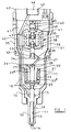
- Figure 1 illustrates part of a unit pump injector which comprises a nozzle body 10 having a bore 11 formed therein, a needle 12 being slidable within the bore 11 and engageable with a seating defined adjacent a blind end of the bore 11 to control the flow of fuel from a delivery chamber 13 defined between the needle 12 and the bore 11 to a plurality of outlet openings 14 located downstream of the seating.
- the needle 12 includes angled thrust surfaces exposed to the fuel pressure within the delivery chamber 13, thus the application of fuel under high pressure to the delivery chamber 13 applies a force to the needle 12 urging the needle 12 away from its seating.
- the bore 11 includes a region of enlarged diameter which defines an annular gallery 15.
- the gallery 15 communicates with a drilling 16 forming part of a supply passage. Flutes or other formations are provided in the needle 12 to permit fuel to flow from the gallery 15 to the delivery chamber 13, the needle 12 further including regions of diameter substantially equal to the diameter of the adjacent parts of the bore 11 to guide the needle 12 for sliding movement within the bore 11.
- the end of the nozzle body 10 remote from the blind end of the bore abuts a spring housing 17.
- the spring housing is provided with drillings 18 which form part of the supply passage.
- the spring housing 17 is provided with a through bore including a region of enlarged diameter which defines a spring chamber 19, the spring chamber 19 being closed by a closure member 20 which abuts the end surface of the spring housing 17 remote from the nozzle body 10.
- a spring 21 is located within the spring chamber 20, the spring 21 extending between the closure member 20 and an abutment member 22 which abuts a projection extending from an upper part of the needle 12 which extends into the spring chamber 19. The spring 21 therefore applies a biasing force to the needle 12, urging the needle 12 into engagement with its seating.
- the spring abutment member 22 includes a region 22 a which is slidable within a bore formed in a projection 20 a of the closure member 20.
- the region 22 a is of piston-like fit within the bore of the projection 20 a .
- the bore of the projection 20 a is provided with a region of slightly enlarged diameter which defines, with the region 22 a , an annular chamber which communicates through a drilling 25 and a groove formed in the upper surface of the closure member 20 with a drilling 26 forming part of the supply passage.
- closure member 20 remote from the spring housing 17 abuts a first distance piece 27.
- the distance piece 27, closure member 20 and region 22 a together define a control chamber 28 which communicates via a restricted or controlled clearance between the region 22 a and the wall of the bore of the closure member 20 with the annular chamber which communicates with the drilling 25. It will be appreciated, therefore, that fuel is able to flow at a restricted rate from the supply passage to the control chamber 28.
- the control chamber 28 further communicates with a drilling 29 formed in the distance piece 27, the drilling 29 communicating with a drilling 30 formed in a control valve housing 31 which abuts the surface of the distance piece 27 remote from the closure member 20.
- the drilling 30 opens into a through bore 32 formed in the control valve housing 31, a control valve member 33 being slidable within the through bore 32 and including a region of enlarged diameter which is engageable with a seating defined around part of the through bore 32 to control communication between the drilling 30 and a groove 34 formed in the upper surface of the distance piece 27, the groove 34 communicating with a low pressure chamber defined, in part, between the control valve housing 31 and a cap nut 35.
- the low pressure chamber communicates with an appropriate fuel reservoir or drain.
- the control valve member 33 carries an armature 36 which is moveable under the influence of the magnetic field generated, in use, by an actuator arrangement 37 including first and second windings 38, 39.
- the actuator arrangement 37 is located within an actuator housing 40 which abuts the control valve housing 31.
- a drain valve housing 41 abuts the surface of the actuator housing 40 remote from the control valve housing 31, the drain valve housing 41 abutting a pump housing 42 including a bore 43 within which a pumping plunger 44 is reciprocable under the influence of a cam and tappet arrangement (not shown) and a return spring (not shown).
- the bore 43 communicates with the supply passage.
- the cap nut 35 is secured to the pump housing 42, the cap nut 35 securing the nozzle body 10, the spring housing 17, the closure member 20, the distance piece 27 and the control valve, actuator and drain valve housings 31, 40, 41 to the pump housing 42.
- the drain valve housing 41 includes a through bore 45 within which a drain valve member 46 is slidable, the drain valve member 46 being engageable with a seating to control communication between the supply passage and a passage 47 formed in the drain valve housing 41 which communicates with the low pressure drain reservoir, in use.
- the drain valve member 46 is secured to an armature 48 moveable under the influence of the magnetic field generated, in use, by the second winding 39 of the actuator arrangement 37.
- a spring 49 is located between the armature 36, 48, appropriate shims being located to achieve the desired level of pre-stressing of the spring 49, the spring 49 urging both the drain valve member 46 and the control valve member 33 away from their seatings towards respective open positions.
- the fuel pressure within the bore 43 and the supply passage is relatively low, and injection of fuel is not taking place.
- the plunger 44 is retracted from the bore 43 under the action of the return spring, such retraction of the plunger 44 drawing fuel into the plunger bore 43 from the drain reservoir past the drain valve member 46.
- the movement of the plunger 44 therefore charges the plunger bore 43 with fuel.
- the plunger 44 will commence inward movement under the action of the cam and tappet arrangement. Whilst the actuator arrangement 37 remains de-energized, such inward movement of the plunger 44 simply displaces fuel past the drain valve member 46 to the low pressure drain.
- the fuel pressure within the bore 43 and the supply passage therefore remains relatively low, and is unable to lift the injector needle 12 away from its seating against the action of the spring 21.
- the actuator arrangement 37 When it is determined that pressurization of fuel is to commence in order to achieve the desired injection pressure at the appropriate point in the operating cycle of the injector, the actuator arrangement 37 is energized, energizing both the first and second windings 38, 39 thereof. Such energization causes the armatures 36, 48 to move towards the actuator arrangement 37, compressing the spring 49 and moving the drain valve member 46 and control valve member 43 into engagement with their respective seatings. As a result, fuel is unable to flow past the drain valve member 46 to the low pressure drain. The continued inward movement of the plunger 44 is therefore unable to displace fuel to the low pressure drain, and the continued movement results in pressurization of the fuel within the plunger bore 43 and the passages and chambers in communication therewith.
- the increase in the fuel pressure results in the fuel pressure within the control chamber 28 rising, fuel being unable to escape from the control chamber 28 as the control valve member 33 engages its seating.
- a relatively large magnitude force is applied to the needle 12 assisting the spring 21 in ensuring that the needle 12 remains in engagement with its seating, thus injection of fuel does not take place, even though the delivery chamber pressure is rising.
- control chamber 28 The communication between the control chamber 28 and the low pressure drain permits the fuel pressure within the control chamber 28 to fall, thus reducing the magnitude of the force applied to the needle 12 urging the needle 12 towards its seating, and a point will be reached beyond which the fuel under pressure within the delivery chamber 13 is able to lift the needle 12 away from its seating, thus permitting fuel to flow to the outlet openings 14 the fuel then being delivered to the combustion space of an associated engine.
- Movement of the needle 12 away from its seating is limited by engagement of the end part of the region 22 a with the first distance piece 27. Such engagement closes the drilling 29, thus breaking the communication between the control chamber 28 and the low pressure drain. As a result, the fuel pressure within the control chamber 28 is able to rise. However, it will appreciated that at this point in the operating cycle of the injector, the increased fuel pressure acts upon only a relatively small effective area, thus the magnitude of the force applied to the needle 12 by the fuel pressure within the control chamber 28 is insufficient to terminate injection.
- the region 22 a is conveniently shaped to define a seating which forms a good seal with the adjacent surface of the distance piece 27.
- the actuator 37 is totally de-energized, and as a result the drain valve member 46 is able to move away from its seating under the action of the spring 49.
- Such movement permits fuel to escape to the low pressure drain reservoir and as a result, the fuel pressure within the delivery chamber 13 falls.
- the fuel pressure within the delivery chamber 13 falls to an extent sufficient to allow the spring 21 to return the needle 12 into engagement with its seating, thus terminating the supply of fuel to the outlet openings 14 and terminating injection.
- Continued inward movement of the plunger 44 continues to displace fuel past the drain valve member 46 to the low pressure drain until the plunger 44 reaches its innermost position, thereafter the plunger 44 being retracted from the bore 43 as described hereinbefore.
- the injection cycle may be modified- by interrupting the injection when the quantity of fuel desired to be delivered during the pilot injection has been delivered by re-energizing the first winding 38 of the actuator 37 to return the control valve member 33 to its closed position, such movement permitting the fuel pressure within the control chamber 28 to rise to an extent sufficient to cause the needle 12 to return into engagement with its seating.
- the main injection is commenced by de-energizing the first winding 38 to relieve the fuel pressure within the control chamber 28. Termination of injection is as described hereinbefore. It will be appreciated that in order to permit the injector to be operated in this manner, the injector must be modified to ensure that the drilling 29 remains in communication with the control chamber 28 even when the needle 12 occupies its fully lifted position.
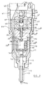
- the injector may be controlled using an actuator arrangement including a single winding, energization of the winding to a high level attracting both armatures towards the actuator to close both valves, energization of the actuator to a lower level generating an attractive force sufficient to retain the drain valve in its closed position, but insufficient to hold the control valve member in its closed position.
- the injection control valve member 33 takes the form of a tubular valve member, the upper end of which is engageable with a surface of the actuator arrangement 37 to control communication between the control chamber 28 and a chamber 31 a defined, in part, by the control valve housing 31 which communicates with the low pressure drain reservoir.
- the control valve member 33 is not spring biased towards an open position.
- a passage 33 a of the tubular valve member 33 communicates with the control chamber 28, and so is exposed to substantially the same fuel pressure. As illustrated, the upper end of the passage 33 a is of enlarged diameter, and the application of fuel under pressure to the passage 33 a of the valve member 33 applies a force to the valve member 33 urging the valve member 33 away from the actuator arrangement 37 against the action of the magnetic attraction between the actuator arrangement 37 and the armature 36.
- the magnitude of the attractive force can be controlled, for example, by controlling the current flowing in the winding 38.
- the fuel pressure within the injector, and in particular within the delivery chamber 13 rises.
- the increasing fuel pressure within the delivery chamber 13 will reach a point beyond which the action of the fuel pressure within the delivery chamber 13 upon the thrust surfaces of the needle 12 will apply a sufficiently large force to the needle 12 to permit the needle 12 to lift away from its seating against the action of the fuel under pressure within the control chamber 28 and the action of the spring 21.
- the fuel pressure within the control chamber 28 is dependent upon the magnitude of the attractive force between the actuator 37 and the armature 36, the fuel pressure within the delivery chamber 13 which causes the needle 12 to lift away from its seating to commence injection can be controlled by controlling the level of energization of the winding 38.
- the region 22 a moves into engagement with a seating defined by a shoulder of the closure member 20 to break communication between the control chamber 28 and the passage 33 a of the valve member 33. As a result, further fuel is unable to escape from the supply passage through the control chamber 28 to the low pressure drain.
- the actuator 37 When it is determined that injection should be terminated, the actuator 37 is totally de-energized, thus allowing the drain valve member 46 to lift away from its seating and permitting fuel to escape to the low pressure drain. As a result, the fuel pressure within the delivery chamber 13 reduces, and a point will be reached beyond which the needle 12 is able to return into engagement with its seating under the action of the spring 21.
- the arrangement illustrated in Figure 2 is advantageous in that the timing of fuel injection is governed by the timing at which the fuel pressure within the system reaches a predetermined pressure controlled by the energization of the first winding 38, rather than by controlling the timing at which the first winding 38 is de-energized.
- the control system used to control operation of the injection can therefore be simplified.
- the restricted communication between the supply passage and the control chamber 28 is by way of a direct, restricted drilling 25 a rather than by way of a controlled clearance between the region 22 a and the bore of the projection 20 a .
- the manufacturing process may be simplified. It will be appreciated that this modification may also be incorporated in the arrangement of Figure 1.
- the actuator 37 may be modified to include a single winding, the actuator being arranged such that when pressurization of fuel is to commence, the actuator is fully energized to attract both armatures towards the actuator.
- the energization level of the actuator may be chosen to ensure that the drain valve member 46 remains in engagement with its seating and to ensure that the control valve member 33 is able to lift away from its seating at the appropriate point in the injection cycle.
- the energization level may be reduced to allow the control valve member 33 to move away from the actuator to permit commencement of injection, the energization level still being sufficient to ensure that the drain valve member 46 remains in engagement with its seating.
Applications Claiming Priority (2)
| Application Number | Priority Date | Filing Date | Title |
|---|---|---|---|
| GB9820237 | 1998-09-18 | ||
| GBGB9820237.7A GB9820237D0 (en) | 1998-09-18 | 1998-09-18 | Fuel injector |
Publications (3)
| Publication Number | Publication Date |
|---|---|
| EP0987431A2 true EP0987431A2 (fr) | 2000-03-22 |
| EP0987431A3 EP0987431A3 (fr) | 2001-01-24 |
| EP0987431B1 EP0987431B1 (fr) | 2003-12-03 |
Family
ID=10839003
Family Applications (1)
| Application Number | Title | Priority Date | Filing Date |
|---|---|---|---|
| EP99307201A Expired - Lifetime EP0987431B1 (fr) | 1998-09-18 | 1999-09-13 | Injecteur de carburant |
Country Status (4)
| Country | Link |
|---|---|
| US (1) | US6267306B1 (fr) |
| EP (1) | EP0987431B1 (fr) |
| DE (1) | DE69913276T2 (fr) |
| GB (1) | GB9820237D0 (fr) |
Cited By (22)
| Publication number | Priority date | Publication date | Assignee | Title |
|---|---|---|---|---|
| EP0992675A2 (fr) * | 1998-10-09 | 2000-04-12 | Lucas Industries Limited | Système de carburant |
| EP0957261A3 (fr) * | 1998-05-15 | 2000-11-22 | Lucas Industries Limited | Système de carburant et pompe utilisable dans ce système |
| EP1081373A2 (fr) * | 1999-08-28 | 2001-03-07 | Delphi Technologies, Inc. | Injecteur à combustible |
| EP1288487A2 (fr) * | 2001-08-31 | 2003-03-05 | Caterpillar Inc. | Dispositif à solenoide avec deux armatures |
| EP1310668A2 (fr) | 2001-11-10 | 2003-05-14 | Robert Bosch Gmbh | Système d'injection de carburant pour un moteur à combustion |
| EP1310667A2 (fr) | 2001-11-08 | 2003-05-14 | Robert Bosch Gmbh | Système d'injection de carburant pour un moteur à combustion |
| WO2003042530A1 (fr) * | 2001-11-13 | 2003-05-22 | Robert Bosch Gmbh | Dispositif d'injection de carburant conçu pour un moteur a combustion interne |
| EP1318293A2 (fr) | 2001-12-07 | 2003-06-11 | Robert Bosch Gmbh | Système d'injection de carburant pour moteur a combustion interne |
| WO2003050408A1 (fr) * | 2001-12-07 | 2003-06-19 | Robert Bosch Gmbh | Dispositif d'injection de carburant pour moteur a combustion interne |
| WO2003054375A1 (fr) | 2001-12-07 | 2003-07-03 | Robert Bosch Gmbh | Dispositif d'injection de carburant pour moteur a combustion interne |
| WO2003054379A1 (fr) * | 2001-12-07 | 2003-07-03 | Volkswagen Mechatronic Gmbh & Co. Kg | Unite pompe-injecteur |
| WO2003058052A1 (fr) | 2002-01-09 | 2003-07-17 | Robert Bosch Gmbh | Piece de commande destinee a des injecteurs a aiguille d'injecteur manoeuvrable |
| WO2003067070A1 (fr) * | 2002-02-08 | 2003-08-14 | Robert Bosch Gmbh | Dispositif d'injection de carburant pour un moteur a combustion interne |
| WO2003069154A1 (fr) * | 2002-02-12 | 2003-08-21 | Robert Bosch Gmbh | Systeme d'injection de carburant pour un moteur a combustion interne |
| WO2003071124A1 (fr) * | 2002-02-20 | 2003-08-28 | Robert Bosch Gmbh | Dispositif d'injection de carburant d'un moteur a combustion interne |
| WO2003078828A1 (fr) * | 2002-03-15 | 2003-09-25 | Robert Bosch Gmbh | Systeme d'injection de carburant pour moteur a combustion interne |
| WO2004016938A1 (fr) * | 2002-07-20 | 2004-02-26 | Robert Bosch Gmbh | Dispositif d'injection de carburant pour moteur a combustion interne |
| WO2004057177A1 (fr) * | 2002-12-20 | 2004-07-08 | Robert Bosch Gmbh | Systeme d'injection de carburant pour moteur a combustion |
| WO2006072757A1 (fr) | 2005-01-07 | 2006-07-13 | Delphi Technologies, Inc. | Appareil d’injection de carburant |
| WO2006130262A1 (fr) * | 2005-05-31 | 2006-12-07 | Caterpillar Inc. | Systeme et procede de regulation pour injecteur de carburant |
| WO2006138083A1 (fr) * | 2005-06-17 | 2006-12-28 | Caterpillar Inc. | Actionneur electromagnetique et procede pour controler un flux de fluide |
| EP2256333A1 (fr) * | 2009-05-19 | 2010-12-01 | Robert Bosch GmbH | Soupape magnétique à fermeture active pour injecteurs magnétiques |
Families Citing this family (17)
| Publication number | Priority date | Publication date | Assignee | Title |
|---|---|---|---|---|
| DE19937988A1 (de) * | 1999-08-11 | 2001-02-15 | Ficht Gmbh & Co Kg | Vorrichtung zum Fördern und/oder Abspritzen von fliessfähigen Medien, insbesondere von Fluiden |
| GB0001766D0 (en) * | 2000-01-27 | 2000-03-15 | Delphi Tech Inc | Fuel injector |
| US6409145B1 (en) * | 2000-02-28 | 2002-06-25 | Delphi Technologies, Inc. | Plunger assembly having a preset spring force pre-load |
| DE10017657A1 (de) * | 2000-04-08 | 2001-10-11 | Bosch Gmbh Robert | Kraftstoffeinspritzventil für Brennkraftmaschinen |
| US6601785B2 (en) * | 2001-06-01 | 2003-08-05 | Siemens Automotive Corporation | Self-locking spring stop for fuel injector calibration |
| US7278593B2 (en) * | 2002-09-25 | 2007-10-09 | Caterpillar Inc. | Common rail fuel injector |
| US7455243B2 (en) * | 2004-03-03 | 2008-11-25 | Caterpillar Inc. | Electronic unit injector with pressure assisted needle control |
| US6976474B1 (en) | 2004-07-19 | 2005-12-20 | Caterpillar Inc. | Mechanically actuated, electronically controlled fuel injection system |
| US7950593B2 (en) * | 2008-06-20 | 2011-05-31 | Caterpillar Inc. | Z orifice feature for mechanically actuated fuel injector |
| US20100096473A1 (en) * | 2008-10-20 | 2010-04-22 | Caterpillar Inc. | Variable flow rate valve for mechnically actuated fuel injector |
| US8967502B2 (en) | 2011-05-11 | 2015-03-03 | Caterpillar Inc. | Dual fuel injector and engine using same |
| US8844842B2 (en) | 2011-08-12 | 2014-09-30 | Caterpillar Inc. | Three-way needle control valve and dual fuel injection system using same |
| US9453483B2 (en) | 2011-08-30 | 2016-09-27 | Caterpillar Inc. | Fuel injector for dual fuel common rail system |
| US8925519B2 (en) | 2011-11-11 | 2015-01-06 | Caterpillar Inc. | Dual fuel common rail system and fuel injector |
| EP2706222B1 (fr) * | 2012-09-06 | 2016-07-13 | Delphi International Operations Luxembourg S.à r.l. | Unité de pompage |
| GB201309118D0 (en) | 2013-05-21 | 2013-07-03 | Delphi Tech Holding Sarl | Fuel Injector |
| EP3153701B1 (fr) * | 2015-10-09 | 2018-12-26 | Continental Automotive GmbH | Injecteur de fluide, moteur à combustion et procédé pour faire fonctionner un moteur à combustion |
Citations (4)
| Publication number | Priority date | Publication date | Assignee | Title |
|---|---|---|---|---|
| US5717372A (en) * | 1995-08-14 | 1998-02-10 | Caterpillar Inc. | Dual armature solenoid |
| EP0823550A1 (fr) * | 1996-08-06 | 1998-02-11 | Lucas Industries Public Limited Company | Injecteur |
| EP0823549A2 (fr) * | 1996-08-06 | 1998-02-11 | Lucas Industries Public Limited Company | Injecteur |
| GB2320292A (en) * | 1994-05-13 | 1998-06-17 | Caterpillar Inc | A method of operating an electronically-controlled unit fuel pump injector for an i.c. engine |
Family Cites Families (6)
| Publication number | Priority date | Publication date | Assignee | Title |
|---|---|---|---|---|
| US4361309A (en) * | 1980-06-23 | 1982-11-30 | Niipondenso Co., Ltd. | Electromagnetic actuator |
| JPH01224454A (ja) * | 1988-03-04 | 1989-09-07 | Yamaha Motor Co Ltd | エンジンの高圧燃料噴射装置 |
| US5463996A (en) * | 1994-07-29 | 1995-11-07 | Caterpillar Inc. | Hydraulically-actuated fluid injector having pre-injection pressurizable fluid storage chamber and direct-operated check |
| US5915624A (en) * | 1997-11-03 | 1999-06-29 | Caterpillar Inc. | Fuel injector utilizing a biarmature solenoid |
| US6113014A (en) * | 1998-07-13 | 2000-09-05 | Caterpillar Inc. | Dual solenoids on a single circuit and fuel injector using same |
| US6059203A (en) * | 1998-09-03 | 2000-05-09 | Caterpillar Inc. | Valve assembly with concentrically linked components and fuel injector using same |
-
1998
- 1998-09-18 GB GBGB9820237.7A patent/GB9820237D0/en not_active Ceased
-
1999
- 1999-09-13 DE DE69913276T patent/DE69913276T2/de not_active Expired - Lifetime
- 1999-09-13 EP EP99307201A patent/EP0987431B1/fr not_active Expired - Lifetime
- 1999-09-14 US US09/395,712 patent/US6267306B1/en not_active Expired - Fee Related
Patent Citations (4)
| Publication number | Priority date | Publication date | Assignee | Title |
|---|---|---|---|---|
| GB2320292A (en) * | 1994-05-13 | 1998-06-17 | Caterpillar Inc | A method of operating an electronically-controlled unit fuel pump injector for an i.c. engine |
| US5717372A (en) * | 1995-08-14 | 1998-02-10 | Caterpillar Inc. | Dual armature solenoid |
| EP0823550A1 (fr) * | 1996-08-06 | 1998-02-11 | Lucas Industries Public Limited Company | Injecteur |
| EP0823549A2 (fr) * | 1996-08-06 | 1998-02-11 | Lucas Industries Public Limited Company | Injecteur |
Cited By (42)
| Publication number | Priority date | Publication date | Assignee | Title |
|---|---|---|---|---|
| EP0957261A3 (fr) * | 1998-05-15 | 2000-11-22 | Lucas Industries Limited | Système de carburant et pompe utilisable dans ce système |
| US6651625B1 (en) | 1998-05-15 | 2003-11-25 | Delphi Technologies, Inc. | Fuel system and pump suitable for use therein |
| EP0992675A2 (fr) * | 1998-10-09 | 2000-04-12 | Lucas Industries Limited | Système de carburant |
| EP0992675A3 (fr) * | 1998-10-09 | 2000-10-11 | Lucas Industries Limited | Système de carburant |
| EP1081373A2 (fr) * | 1999-08-28 | 2001-03-07 | Delphi Technologies, Inc. | Injecteur à combustible |
| EP1081373A3 (fr) * | 1999-08-28 | 2002-04-10 | Delphi Technologies, Inc. | Injecteur à combustible |
| US6502555B1 (en) | 1999-08-28 | 2003-01-07 | Delphi Technologies, Inc. | Fuel injector |
| EP1288487A2 (fr) * | 2001-08-31 | 2003-03-05 | Caterpillar Inc. | Dispositif à solenoide avec deux armatures |
| US6856222B1 (en) | 2001-08-31 | 2005-02-15 | Caterpillar Inc. | Biarmature solenoid |
| EP1288487A3 (fr) * | 2001-08-31 | 2004-03-17 | Caterpillar Inc. | Dispositif à solenoide avec deux armatures |
| EP1310667A2 (fr) | 2001-11-08 | 2003-05-14 | Robert Bosch Gmbh | Système d'injection de carburant pour un moteur à combustion |
| EP1310667A3 (fr) * | 2001-11-08 | 2004-12-15 | Robert Bosch Gmbh | Système d'injection de carburant pour un moteur à combustion |
| EP1310668A2 (fr) | 2001-11-10 | 2003-05-14 | Robert Bosch Gmbh | Système d'injection de carburant pour un moteur à combustion |
| EP1310668A3 (fr) * | 2001-11-10 | 2004-12-15 | Robert Bosch Gmbh | Système d'injection de carburant pour un moteur à combustion |
| WO2003042530A1 (fr) * | 2001-11-13 | 2003-05-22 | Robert Bosch Gmbh | Dispositif d'injection de carburant conçu pour un moteur a combustion interne |
| EP1318293A2 (fr) | 2001-12-07 | 2003-06-11 | Robert Bosch Gmbh | Système d'injection de carburant pour moteur a combustion interne |
| WO2003054379A1 (fr) * | 2001-12-07 | 2003-07-03 | Volkswagen Mechatronic Gmbh & Co. Kg | Unite pompe-injecteur |
| EP1318293A3 (fr) * | 2001-12-07 | 2006-03-22 | Robert Bosch Gmbh | Système d'injection de carburant pour moteur a combustion interne |
| US6976638B2 (en) | 2001-12-07 | 2005-12-20 | Robert Bosch Gmbh | Fuel injection system for an internal combustion engine |
| WO2003050408A1 (fr) * | 2001-12-07 | 2003-06-19 | Robert Bosch Gmbh | Dispositif d'injection de carburant pour moteur a combustion interne |
| WO2003054375A1 (fr) | 2001-12-07 | 2003-07-03 | Robert Bosch Gmbh | Dispositif d'injection de carburant pour moteur a combustion interne |
| WO2003058052A1 (fr) | 2002-01-09 | 2003-07-17 | Robert Bosch Gmbh | Piece de commande destinee a des injecteurs a aiguille d'injecteur manoeuvrable |
| DE10200531A1 (de) * | 2002-01-09 | 2003-07-24 | Bosch Gmbh Robert | Steuerteil für Injektoren mit schaltbarer Düsennadel |
| WO2003067070A1 (fr) * | 2002-02-08 | 2003-08-14 | Robert Bosch Gmbh | Dispositif d'injection de carburant pour un moteur a combustion interne |
| US6981653B2 (en) | 2002-02-08 | 2006-01-03 | Robert Bosch Gmbh | Fuel injection device for an internal combustion engine |
| WO2003069154A1 (fr) * | 2002-02-12 | 2003-08-21 | Robert Bosch Gmbh | Systeme d'injection de carburant pour un moteur a combustion interne |
| US7025284B2 (en) | 2002-02-12 | 2006-04-11 | Robert Bosch Gmbh | Fuel injection system for an internal combustion engine |
| US6886535B2 (en) | 2002-02-20 | 2005-05-03 | Robert Bosch Gmbh | Fuel-injection device for an internal combustion engine |
| WO2003071124A1 (fr) * | 2002-02-20 | 2003-08-28 | Robert Bosch Gmbh | Dispositif d'injection de carburant d'un moteur a combustion interne |
| WO2003078828A1 (fr) * | 2002-03-15 | 2003-09-25 | Robert Bosch Gmbh | Systeme d'injection de carburant pour moteur a combustion interne |
| WO2004016938A1 (fr) * | 2002-07-20 | 2004-02-26 | Robert Bosch Gmbh | Dispositif d'injection de carburant pour moteur a combustion interne |
| WO2004057177A1 (fr) * | 2002-12-20 | 2004-07-08 | Robert Bosch Gmbh | Systeme d'injection de carburant pour moteur a combustion |
| WO2006072757A1 (fr) | 2005-01-07 | 2006-07-13 | Delphi Technologies, Inc. | Appareil d’injection de carburant |
| WO2006130262A1 (fr) * | 2005-05-31 | 2006-12-07 | Caterpillar Inc. | Systeme et procede de regulation pour injecteur de carburant |
| US7255091B2 (en) | 2005-05-31 | 2007-08-14 | Caterpillar, Inc. | Fuel injector control system and method |
| GB2440092A (en) * | 2005-05-31 | 2008-01-16 | Caterpillar Inc | Fuel injector control system and method |
| GB2440092B (en) * | 2005-05-31 | 2010-05-05 | Caterpillar Inc | Fuel injector control system and method |
| WO2006138083A1 (fr) * | 2005-06-17 | 2006-12-28 | Caterpillar Inc. | Actionneur electromagnetique et procede pour controler un flux de fluide |
| GB2442882A (en) * | 2005-06-17 | 2008-04-16 | Caterpillar Inc | Electromagnetic actuator and method for controlling fluid flow |
| GB2442882B (en) * | 2005-06-17 | 2010-05-05 | Caterpillar Inc | Electromagnetic actuator and method for controlling fluid flow |
| US9140224B2 (en) | 2005-06-17 | 2015-09-22 | Caterpillar Inc. | Electromagnetic actuator and method for controlling fluid flow |
| EP2256333A1 (fr) * | 2009-05-19 | 2010-12-01 | Robert Bosch GmbH | Soupape magnétique à fermeture active pour injecteurs magnétiques |
Also Published As
| Publication number | Publication date |
|---|---|
| DE69913276T2 (de) | 2004-09-23 |
| EP0987431B1 (fr) | 2003-12-03 |
| DE69913276D1 (de) | 2004-01-15 |
| US6267306B1 (en) | 2001-07-31 |
| EP0987431A3 (fr) | 2001-01-24 |
| GB9820237D0 (en) | 1998-11-11 |
Similar Documents
| Publication | Publication Date | Title |
|---|---|---|
| EP0987431B1 (fr) | Injecteur de carburant | |
| EP0823550B1 (fr) | Injecteur | |
| US6471142B1 (en) | Fuel injector | |
| EP0889230B1 (fr) | Injecteur de combustible | |
| EP0269289A2 (fr) | Pompe-injecteur pour moteur diesel à fermeture assistée de l'aiguille d'injecteur par la pression de décharge | |
| EP1382836A1 (fr) | Injecteur à combustible | |
| EP1163440B1 (fr) | Injecteur de carburant | |
| EP0943797A1 (fr) | Injecteur à combustible | |
| US6405940B2 (en) | Fuel injector | |
| EP0987430B1 (fr) | Injecteur de combustible | |
| EP1081373A2 (fr) | Injecteur à combustible | |
| EP1098087B1 (fr) | Injecteur de combustible | |
| GB2341893A (en) | Two-stage electromagnetically actuated fuel injector for i.c. engines | |
| EP0921302A2 (fr) | Injecteur de combustible | |
| EP0987432B1 (fr) | Injecteur de combustible | |
| US6209805B1 (en) | Fuel injector | |
| US6811092B2 (en) | Fuel injector nozzle with pressurized needle valve assembly | |
| US5333588A (en) | Pump/injector | |
| US6321999B1 (en) | Fuel injector | |
| EP1065368A2 (fr) | Injecteur de carburant | |
| EP1024281A2 (fr) | Procédé et dispositif pour fournir un taux et une pression d'injection réglables dans un injecteur de combustible | |
| WO1993021439A1 (fr) | Pompe de carburant |
Legal Events
| Date | Code | Title | Description |
|---|---|---|---|
| PUAI | Public reference made under article 153(3) epc to a published international application that has entered the european phase |
Free format text: ORIGINAL CODE: 0009012 |
|
| AK | Designated contracting states |
Kind code of ref document: A2 Designated state(s): DE ES FR GB IT |
|
| AX | Request for extension of the european patent |
Free format text: AL;LT;LV;MK;RO;SI |
|
| PUAL | Search report despatched |
Free format text: ORIGINAL CODE: 0009013 |
|
| AK | Designated contracting states |
Kind code of ref document: A3 Designated state(s): AT BE CH CY DE DK ES FI FR GB GR IE IT LI LU MC NL PT SE |
|
| AX | Request for extension of the european patent |
Free format text: AL;LT;LV;MK;RO;SI |
|
| RIC1 | Information provided on ipc code assigned before grant |
Free format text: 7F 02M 57/02 A, 7F 02M 47/02 B, 7F 02M 59/46 B, 7F 02M 59/36 B |
|
| RAP1 | Party data changed (applicant data changed or rights of an application transferred) |
Owner name: DELPHI TECHNOLOGIES, INC. |
|
| 17P | Request for examination filed |
Effective date: 20010702 |
|
| AKX | Designation fees paid |
Free format text: DE ES FR GB IT |
|
| 17Q | First examination report despatched |
Effective date: 20020412 |
|
| GRAH | Despatch of communication of intention to grant a patent |
Free format text: ORIGINAL CODE: EPIDOS IGRA |
|
| GRAS | Grant fee paid |
Free format text: ORIGINAL CODE: EPIDOSNIGR3 |
|
| GRAA | (expected) grant |
Free format text: ORIGINAL CODE: 0009210 |
|
| AK | Designated contracting states |
Kind code of ref document: B1 Designated state(s): DE ES FR GB IT |
|
| PG25 | Lapsed in a contracting state [announced via postgrant information from national office to epo] |
Ref country code: IT Free format text: LAPSE BECAUSE OF FAILURE TO SUBMIT A TRANSLATION OF THE DESCRIPTION OR TO PAY THE FEE WITHIN THE PRESCRIBED TIME-LIMIT;WARNING: LAPSES OF ITALIAN PATENTS WITH EFFECTIVE DATE BEFORE 2007 MAY HAVE OCCURRED AT ANY TIME BEFORE 2007. THE CORRECT EFFECTIVE DATE MAY BE DIFFERENT FROM THE ONE RECORDED. Effective date: 20031203 |
|
| REG | Reference to a national code |
Ref country code: GB Ref legal event code: FG4D |
|
| REF | Corresponds to: |
Ref document number: 69913276 Country of ref document: DE Date of ref document: 20040115 Kind code of ref document: P |
|
| PG25 | Lapsed in a contracting state [announced via postgrant information from national office to epo] |
Ref country code: ES Free format text: LAPSE BECAUSE OF FAILURE TO SUBMIT A TRANSLATION OF THE DESCRIPTION OR TO PAY THE FEE WITHIN THE PRESCRIBED TIME-LIMIT Effective date: 20040314 |
|
| ET | Fr: translation filed | ||
| PLBE | No opposition filed within time limit |
Free format text: ORIGINAL CODE: 0009261 |
|
| STAA | Information on the status of an ep patent application or granted ep patent |
Free format text: STATUS: NO OPPOSITION FILED WITHIN TIME LIMIT |
|
| 26N | No opposition filed |
Effective date: 20040906 |
|
| PGFP | Annual fee paid to national office [announced via postgrant information from national office to epo] |
Ref country code: GB Payment date: 20100908 Year of fee payment: 12 |
|
| REG | Reference to a national code |
Ref country code: FR Ref legal event code: TP |
|
| GBPC | Gb: european patent ceased through non-payment of renewal fee |
Effective date: 20110913 |
|
| PG25 | Lapsed in a contracting state [announced via postgrant information from national office to epo] |
Ref country code: GB Free format text: LAPSE BECAUSE OF NON-PAYMENT OF DUE FEES Effective date: 20110913 |
|
| PGFP | Annual fee paid to national office [announced via postgrant information from national office to epo] |
Ref country code: FR Payment date: 20121001 Year of fee payment: 14 |
|
| PGFP | Annual fee paid to national office [announced via postgrant information from national office to epo] |
Ref country code: DE Payment date: 20120927 Year of fee payment: 14 |
|
| REG | Reference to a national code |
Ref country code: GB Ref legal event code: 732E Free format text: REGISTERED BETWEEN 20130425 AND 20130501 |
|
| REG | Reference to a national code |
Ref country code: FR Ref legal event code: ST Effective date: 20140530 |
|
| REG | Reference to a national code |
Ref country code: DE Ref legal event code: R082 Ref document number: 69913276 Country of ref document: DE Representative=s name: MANITZ, FINSTERWALD & PARTNER GBR, DE |
|
| REG | Reference to a national code |
Ref country code: DE Ref legal event code: R119 Ref document number: 69913276 Country of ref document: DE Effective date: 20140401 |
|
| REG | Reference to a national code |
Ref country code: DE Ref legal event code: R082 Ref document number: 69913276 Country of ref document: DE Representative=s name: MANITZ, FINSTERWALD & PARTNER GBR, DE Effective date: 20140702 Ref country code: DE Ref legal event code: R081 Ref document number: 69913276 Country of ref document: DE Owner name: DELPHI INTERNATIONAL OPERATIONS LUXEMBOURG S.A, LU Free format text: FORMER OWNER: DELPHI TECHNOLOGIES HOLDING S.A.R.L., BASCHARAGE, LU Effective date: 20140702 |
|
| PG25 | Lapsed in a contracting state [announced via postgrant information from national office to epo] |
Ref country code: FR Free format text: LAPSE BECAUSE OF NON-PAYMENT OF DUE FEES Effective date: 20130930 Ref country code: DE Free format text: LAPSE BECAUSE OF NON-PAYMENT OF DUE FEES Effective date: 20140401 |