-
The present invention relates to a communication control
method preferably applied to a case where various information
is transmitted by means of a wireless signal, for example, to
construct a local area network (LAN) among a plurality of
devices, and a transmission apparatus using this control
method.
-
Conventionally, in a relatively small range such as home,
office or the like, when a local area network is constructed
among a plurality of apparatus such as various video
apparatus, a personal computer machine, its periphery
apparatus or the like so as to transmit data handled by these
apparatus, a wireless signal transmitter/receiver (a wireless
transmission apparatus) is connected to each apparatus so as
to enable data transmission through wireless transmission,
instead of direct connection among apparatuses via a signal
line.
-
A local area network is constructed through wireless
transmission, thereby making it possible to simplify a system
configuration without requiring direct connection among
apparatus via a signal line or the like.
-
In the meantime, in the case where a local area network
is constructed by using a plurality of wireless transmission
apparatuses, if signals are transmitted simultaneously from a
plurality of transmission apparatuses using a same transmission
bandwidth, a transmission error may occur. Thus, communication
among the respective transmission apparatuses in the network is
required to access-control by means of any method.
-
As a conventionally known access control method, for
example, in a small scale wireless network, there is exemplified
a method for integrally managing communication among
transmission apparatuses (nodes) in the network by means of a
transmission apparatus (a route node) serving as a central part
using a start-type connection.
-
However, to perform transmission processing using such
star-type connection, it is presumed that a transmission
apparatus serving as a central control station performing
processing for transmission control is capable of performing
wireless communication directly with all other transmission
apparatuses in a network system. Therefore, there has been a
problem that a wireless communication network construction range
is limited within the range capable of directly making
communication with the central control station; and the thus
constructed network is available in a limited range, which
depends on a transmission output of an electric wave of the
central control station.
-
In addition, during transmission control processing
using star-type connection, with respect to transmission control
or network management also, in the case where direct
communication with the central control station is disabled, it
has been necessary to disconnect the corresponding transmission
apparatus from the network. Therefore, there has been a problem
that, in the case where a mobile station freely movable in the
network is admitted as a transmission apparatus, control by the
central control station becomes very complicated. That is, for
the central control station to grasp a position of the mobile
station, it has been necessary to transmit and receive a signal
for connection check at a short period of time, and frequently
supervise a connection state between the central control station
and the mobile station.
-
To solve these problems, for example, it is considered
to construct a distributed network configuration in which
communication is made only between stations capable of
performing direct communication instead of predetermination of
the central control station. In the case of this distributed
network, if a distance to a necessary destination station is
distant, it is required to transmit data by relaying a number of
stations. Every time such relaying is performed, it is required
to perform processing for transmission start with the
destination station for communication. As a result, there is a
problem that data transmission is delayed every time the number
of steps performing relaying is increased.
-
It is an object of the present invention to well control
a station incapable of directly making communication with a
control station in the case where an attempt is made to
control communication in a network system by means of the
control station.
-
As a first aspect of the present invention, there is
provided a communication control method comprising:
- specifying a frame period by means of a predetermined
signal;
- setting a management data transmission region in the
frame period; and
- when a common information to be transmitted from a
control station is received by a plurality of communication
stations, any of the communication stations repeatedly
transmitting the received common information.
-
-
According to this communication control method, common
information is repeatedly transmitted in a communication
station other than the control station, thereby making it
possible to receive the common information even in a
communication station incapable of directly making
communication with the control station.
-
As a second aspect of the present invention, there is
provided a communication control method for controlling an
access of wireless communication among a plurality of
communication stations by means of a control station, said
control method comprising:
- specifying a frame period by a predetermined signal;
- setting a management data transmission region in the
frame period;
- allocating a plurality of slots in the management data
transmission region, the plurality of communication stations or
a control station individually transmitting data concerning
communication states in the respective stations; and
- said control station recognizing the presence of a
station incapable of directly making wireless communication
based on a transmission state of data concerning the
communication state.
-
-
According to this communication control method, the
control station recognizes the presence of a station incapable
of directly making wireless communication, and the control
station can take action to execute communication control
processing for the station.
-
As a third aspect of the present invention, there is
provided a transmission apparatus comprising:
- a timing setting means for setting a frame period based
on a predetermined signal and setting a management transmission
region in the frame period;
- a receiving means for receiving management data to be
transmitted from other transmission apparatuses in the
management data transmission region; and
- a transmitting means for transmitting common information
in management data which said receiving means has received at a
predetermined timing.
-
-
According to this transmission apparatus, the common
information in the management data received by the receiving
means can be transmitted from transmitting means to other
transmission apparatuses.
-
As a fourth aspect of the present invention, there is
provided a transmission apparatus comprising:
- a timing setting means for setting a frame period based
on a predetermined signal and setting a management data
transmission region composed of a plurality of slots in the
frame period;
- a transmitting means for transmitting data on a state of
communication with other transmission apparatuses in a
predetermined slot in the management data transmission region;
- a receiving means for receiving data in a slot other
than said predetermined slots in said management data
transmission region; and
- a control means for recognizing the presence of a
transmission apparatus incapable of directly making
communication with said control apparatus from data on
communication state which said receiving mean has received.
-
-
According to this transmission apparatus, the presence
of a transmission apparatus incapable of directly making
communication with the control apparatus is recognized, making
it possible to handle the transmission apparatus.
-
Embodiments of the invention will now be described, by
way of example only, with reference to the accompanying
drawings in which:
- FIG. 1 is a structural view showing an example of a
communication system according to one embodiment of the
present invention;
- FIG. 2 is an illustrative view showing an example of a
physical topology map according to one embodiment of the
present invention;
- FIG. 3 is a block diagram showing an example of a
configuration of a transmission apparatus according to one
embodiment of the present invention;
- FIG. 4 is an illustrative view showing a frame
configuration example according to one embodiment of the
present invention;
- FIG. 5 is a timing chart showing an example of
processing at station synchronous transmission and receiving
interval according to one embodiment of the present invention;
- FIG. 6 is an illustrative view showing a state of
transmission among stations based on processing at the station
synchronous transmission and receiving interval shown in FIG.
5;
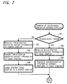
- FIG. 7 is a flow chart showing an example of processing
operations at the station synchronous transmission and receiving
interval according to one embodiment of the present invention;
- FIG. 8 is a timing chart showing an example of
processing at the management information broadcasting interval
according to one embodiment of the present invention;
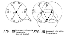
- FIG. 9 is an illustrative view showing a state of
transmission among stations based on processing at the
management information broadcasting interval shown in FIG. 8;
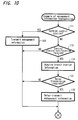
- FIG. 10 is a flow chart showing an example of processing
operations at the management information broadcasting interval
according to one embodiment of the present invention;
- FIG. 11 is a timing chart showing an example of
processing at the management information broadcasting interval
according to another embodiment of the present invention;
- FIG. 12 is an illustrative view showing a state of
transmission among stations based on processing at the
management information broadcasting interval shown in FIG. 11;
- FIG. 13 is a flow chart showing an example of processing
operations at the management information broadcasting interval
according to another embodiment of the present invention;
- FIG. 14 is a timing chart showing an example of
processing at the management information broadcasting interval
according to another embodiment of the present invention (an
example of unsuccessful reception at the control station
notification interval at any station); and
- FIG. 15 is an illustrative view showing a state of
transmission among stations based on processing at the
management information broadcasting interval shown in FIG. 14.
-
-
Hereinafter, an embodiment of the present invention will
be described with reference to FIG. 1 to FIG. 10.
-
In this embodiment, the present invention is applied to a
network system constructed as a system for transmitting and
receiving video data, voice data, computer-use data or the
like at, for example, home or in a relatively small station or
the like. Now, a system configuration of this embodiment will
be described with reference to FIG. 1. In the network system
of this embodiment, the maximum number of wireless
transmission apparatuses configuring the network is
predetermined. For example, a maximum of 16 wireless
transmission apparatuses are available to construct the
network. FIG. 1 shows a state in which eight wireless
transmission apparatuses 1 to 7 and 10 are allocated. To each
of these transmission apparatuses 1 to 7 and 10, antennas 1a
to 7a and 10a are respectively connected to perform
transmission and receiving. To each of the wireless
transmission apparatuses 1 to 7 and 10, various processing
apparatus (not shown) such as a video signal reproducing
apparatus, a monitor apparatus, a computer machine, a printer
apparatus and so on are individually connected. In the case
where data transmission is required among these processing
apparatus, data is transmitted via a connected wireless
transmission apparatus.
-
The eight wireless transmission apparatuses 1 to 7 and
10 each function as a node that is a communication stations, and
each apparatus is assigned an identification number ID
individually in advance. That is, the transmission apparatus 1C
is assigned #0 as its identification numbers ID, and the
transmission apparatuses 1 to 7 are assigned identification
numbers ID from #1 to #7 in order.
-
In this case, a system configuration is such that an
arbitrary one wireless transmission apparatus in the network
system is set as a route node that functions as a central
control station, and wireless communication among nodes is
executed by means of polling control from the control station.
Basically, it is ideal that this control station uses a wireless
transmission apparatus allocated at a position capable of
directly making wireless communication with all other
communication stations in the system. Here, the wireless
transmission apparatus 10 whose identification number ID is #0,
allocated at a substantial center in the network system is
defined as a central control station. A so-called start-type
connection configuration is such that other peripheral
communication stations are controlled from this central route
node. In the foregoing description, "communication stations",
which is merely referred to as, is inclusive of a central
control station.
-
Here in this embodiment, the wireless transmission
apparatus 7 whose identification number ID is #7 is arranged at
a position incapable of directly making wireless communication
with the wireless transmission apparatus 10 that is a central
control station thereof. The wireless transmission apparatus 7
is arranged at a position capable of directly making
communication between the wireless transmission apparatuses 3
and 6 whose identification numbers IDs are #3 and #6,
respectively.
-
FIG. 2 is a view showing a physical topology map that
present a communication state between stations when each
communication station and the control station in this embodiment
are arranged, wherein direct communication is enabled between
connected communication stations indicated by the arrow. In the
figure, communication stations 1 to 7 and 10 each capable of
directly making communication with adjacently positioned
communication stations. For example, the communication station
1 whose identification number ID is #1 is capable of directly
making communication with the communication stations 2, 4, and
10 whose identification number IDs are #2, #4, and #0, which are
arranged at the periphery of communication station 1. This
applies to the other communication stations; and a communication
station (a control station) arranged at a substantial center is
capable of directly making communication with all of
communication stations 1 to 6 other than communication station 7
whose identification number ID is #7. In the case where
communication is performed between communication stations
incapable of directly making communication, transmission
processing is performed by other communication stations by
relaying transmission data.
-
In FIG. 3, there is shown a configuration example of the
wireless transmission apparatuses 1 to 7 and 10 each configuring
communication stations. In the figure, basically, the wireless
transmission apparatuses 1 to 7 and 10 each are commonly
configured (except that only an control configuration adopted to
function as a central control station differs from other
communication stations). These apparatus each are provided with
an antenna 21 and a wireless processing unit 22 connected to the
antenna 21, the wireless processing unit performing wireless
transmission processing and wireless receiving processing, and
is configured to enable wireless transmission with other
transmission apparatuses. In this case, as a transmission
system in which transmission and receiving are performed at the
wireless processing unit 22 of this embodiment, for example, a
transmission system using a multi-carrier signal called an OFDM
(Orthogonal Frequency Division Multiples) is applied. As a
frequency used for transmission and receiving, for example, a
very high frequency band (for example 5 GHz band) is used. In
addition, in the case of this embodiment, a relatively weak
transmission output is set. For example, for use in indoor,
there is provided an output capable of wireless transmission in
a relatively short distance from several meters to several tens
of meters.
-
There is provided a data conversion unit 23 for
performing data conversion of a signal received at the wireless
processing unit 22 and data conversion of a signal to be
transmitted at the wireless processing unit 22. The converted
data at the data conversion unit 23 is supplied to a connected
processor via an interface unit 24, and data to be supplied from
the connected processing unit is supplied to the data conversion
unit 23 via the interface unit 24, thereby enabling conversion
processing.
-
Each unit in the wireless transmission apparatus is
configured to execute processing based on control of a control
unit 25 configured by micro-computers or the like. In this
case, when the wireless processing unit 22 receives a control
signal, the received control signal is supplied to the control
unit 25 via the data conversion unit 23, and the control unit 25
sets each unit in a state indicated by the received control
signal. In addition, a control signal to be transmitted from
the control unit 25 to other transmission apparatus is supplied
from the control unit 25 to the wireless processing unit 22 via
the data conversion unit 23, thereby causing its wireless
transmission. When an asynchronous signal is received, the
control unit 25 is constructed to judge a receiving timing of
that synchronous signal, set a frame period based on the
synchronous signal, and execute communication control processing
at that frame period. In addition, an internal memory 26 is
connected to the control unit 25 so that data required for
communication control is temporarily stored in the internal
memory 26.
-
FIG. 4 shows a configuration of a signal to be
transmitted among communication stations (wireless transmission
apparatuses 1 to 7 and 10) in the network system of this
embodiment. In this embodiment, the network system is
configured such that a frame period is specified, and data is
transmitted. That is, as shown in FIG. 4, a predetermined
single-frame interval is specified, a predetermined interval at
the head portion of the single-frame interval is defined as a
management information transmission region, and a management
information broadcasting interval and a local synchronous
transmission and receiving interval are set in the management
information transmission region. In addition, an interval other
than the management information transmission region of each
frame is defined as a media information transmission region. In
this media information transmission region, various data is
transmitted by means of polling control or the like.
-
In the management information broadcasting interval,
management information common to the system is transmitted from
the central control station 10. The management information to
be transmitted includes, for example, synchronous data required
to obtain frame synchronism in the network system;
identification number data specific to the network system; and
data of topology map in the network or the like.
-
In the station or local synchronous transmission and
receiving interval in one frame, a predetermined number of slots
(16 in this case) are set at an equal interval, and 16 slots in
such one frame are allocated respectively to 16 communication
stations in this network system. These allocated slots include,
for example, a slot for communication station whose
identification number ID is #0; a slot for communication station
whose identification number ID is #1; a slot for communication
station whose identification number ID is #2;··· a slot for
communication station whose identification number ID is #15 in
an ascending order. The allocated slots for communication
stations each are constructed to transmit a local synchronous
signal from communication station corresponding to the slot.
Here, since the network system is composed of eight
communication stations, eight slots (eight slots from the head)
are used, and the remaining slots are not used (i.e., data is
not transmitted to the remaining slots). The data of
identification number ID assigned to each communication station
is supplied to the local synchronous signal. The signal
includes data concerning the communication station capable of
being received at that station (data produced based on the
receiving state of the local synchronous signal before one
frame) or the like.
-
Local synchronous signals to be transmitted in each slot
at the local synchronous transmission and receiving interval are
received and processed at each communication station in the
network system. The transmission processing and receiving
processing of the local synchronous signal will be described
later.
-
In the media information transmission region, data
transfer (transmission) processing is performed among
communication stations based on an access control of the central
control station. The access control by this central control
station is executed by means of polling control from the central
control station, for example. In this polling control
processing, the communication stations each are called in order
from the central control station by means of a polling response
request signal, and transmission is sequentially executed for
each communication station.
-
In the communication station of identification number ID
specified by the polling response request signal, when data to
be transmitted is present, data transmission processing is
performed immediately after the polling response request signal
has been received. As the transmission processing at this time,
it is considered that data transfers in asynchronous (non-synchronizing)
transfer mode and isochronous (synchronizing)
transfer mode are used depending on type of data to be
transmitted. With respect to the asynchronous and isochronous
transfer modes, for example, the asynchronous transfer mode is
used for transmission of relatively short data such as control
data; and the isochronous transfer mode is used for transmission
of data requiring a real-time transfer such as video data, voice
data or the like. As such transmission control system using
polling control, for example, a system conforming to the
IEEE1394 Standard is applicable.
-
Next, the transmission processing and receiving
processing of local synchronous signal will be described with
respect to FIG. 5. As described previously, 16 slots are
provided in the local synchronous transmission and receiving
interval in one frame. Hereinafter, it is assumed that eight
slots from a 0th slot 0 to a seventh slot are prepared, and the
respective slots are individually allocated for communication
stations 10 and 1 to 7 for clarity.
-
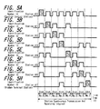
In FIG. 5, A to H each shows a communication state at
the local synchronous transmission and receiving interval in
eight communication stations each. In FIG. 5, A designates the
state in communication station 10 that is the central control
station, and B to H each designate the state from communication
stations 1 to 7 in order. In FIG. 5, the range marked with
diagonal line designates as follows: Transmission processing
'Tx' is performed at the wireless processing unit 22 that is
transmitting means of that communication station, and wireless
transmission is done from the antenna 21. In the other pulse-shaped
leading interval, the transmitted signal from another
communication station is properly received and processed at the
wireless processing unit 22 that is a receiving means of the
communication station. In an interval free of pulse-shaped
leading, a signal cannot be properly received (i.e., data cannot
be decoded correctly by attempting reception).
-
In the communication station 10 whose identification
number ID is #0 that is a central control station, as shown by A
in FIG. 5, transmission processing 'Tx' is performed for a
station synchronous signal at an interval of 0th slot, and
receiving processing is performed in the other slots (intervals
in slot 1 and subsequent). At reception in intervals up to the
sixth slot, communication stations 1 to 6 allocated in these
slots are placed at a position capable of directly making
wireless communication with communication station 10, and thus,
data included in the receiving signal can be correctly decoded.
In contrast, at an interval of seventh slot, communication
station 7 is not placed at a position capable of directly making
wireless communication with communication station 10, and data
cannot be received at this slot position. That is, when a
transmission state of the station synchronous signals to be
transmitted from the station 10 to the 0th slot is shown by A in
FIG. 6, communication stations 1 to 6 whose identification
numbers IDs are #1 to #6 are positioned within the range in
which the signal transmitted from communication station 10
arrives, and the station synchronous signals from communication
station 10 are correctly received at communication stations 1 to
6. However, communication station 7 whose identification number
ID is #7 that is at a distant position cannot receive the local
synchronous signal from communication station 10.
-
In communication stations 1 to 7 whose identification
numbers IDs are #1 to #7, as shown by B to H in FIG. 5, the
station synchronous signal is transmitted at the slot position
allocated for each communication station, and receiving
processing is performed at the other slot position. That is, in
communication station 1 whose identification number ID is #1, as
shown by B in FIG. 5, transmission processing 'Tx' is performed
for a node synchronous signal in the first slot, and receiving
processing is performed in the other slots. At this time, the
communication stations whose positions are adjacent to
communication station 1 whose identification number ID is #1 are
communication stations 10, 2, and 4 whose identification numbers
IDs are #0, #2, and #4. In communication station 1, as shown by
B in FIG. 5, only the node synchronous signals to be transmitted
to the 0th slot, the second slot, and the fourth slot can be
correctly received and processed. In addition, when a
transmission state of the station synchronous signals to be
transmitted from communication station 1 to the first slot is
shown by B in FIG. 6, communication stations 10, 2, and 4 whose
identification numbers IDs are #0, #2, and #4 are positioned
within the range of the signal transmitted from communication
station 1 at which the signal to be transmitted from
communication station 1 arrives, and the station synchronous
signals from communication station 1 are correctly received at
communication stations 2, 4, and 10.
-
In communication station 2 whose identification number
ID is #2, as shown by C in FIG. 5, transmission processing 'Tx'
is performed for the station synchronous signal in the second
slot, and receiving processing is performed in the other slots.
At this time, the communication stations at positions adjacent
to the communication station 2 are communication stations 10, 1,
and 3 whose identification numbers IDs are #0, #1, and #3. In
communication station 2, as shown by C in FIG. 5, only the
station synchronous signals to be transmitted from these
communication stations to the 0th slot, the first slot and the
third slot can be correctly received and processed. In
addition, when a transmission state of the station synchronous
signals to be transmitted from communication station 2 to the
second slot is shown by C in FIG. 6, communication stations 10,
1, and 3 whose identification numbers IDs are #0, #1, and #3 are
positioned within the range at which the signal to be
transmitted from communication station 2 arrives, and the
station synchronous signals from communication station 2 are
correctly received at communication stations 10, 1, and 3 whose
identification numbers IDs are #0, #1, and #3.
-
In communication station 3 whose identification number
ID is #3, as shown by D in FIG. 5, transmission processing 'Tx'
is performed for the station synchronous signal in the third
slot, and receiving processing is performed in the other slots.
At this time, the communication stations whose positions are
adjacent to communication station 3 are communication stations
10, 2, 6, and 7 whose identification numbers IDs are #0, #2, #6
and #7. In communication station 3, as shown by D in FIG. 5,
only the station synchronous signals to be transmitted from
these communication stations to the 0th slot, the second slot,
the sixth slot and the seventh slot can be correctly received
and processed. In addition, when a transmission state of the
station synchronous signals to be transmitted from communication
station 3 to the third slot is shown by D in FIG. 6,
communication stations 10, 2, 6, and 7 whose identification
numbers IDs are #0, #2, #6, and #7 are positioned within the
range at which the signal to be transmitted from communication
station 3 arrives, and the station synchronous signals from
communication station 3 are correctly received at communication
stations 10, 2, 6, and 7 whose identification numbers IDs are
#0, #2, #6, and #7.
-
In communication station 4 whose identification number
ID is #4, as shown by E in FIG. 5, transmission processing 'Tx'
of the station synchronous signal is performed in the fourth
slot, and receiving processing is performed in other slots. At
this time, the communication stations at their positions
adjacent to communication station 4 are communication stations
10, 1, and 5 whose identification numbers IDs are #0, #1, and
#5. In communication station 4, as shown by E in FIG. 5, only
station synchronous signals to transmitted to the 0th slot, the
first slot, and the fifth slot can be correctly received and
processed from these communication stations. In addition, when
a transmission state of the station synchronous signal to be
transmitted from communication station 4 to the fourth slot is
shown by E in FIG. 6, communication stations 10, 1, and 5 whose
identification numbers IDs are #0, #1, and #5 are positioned
within the range at which the signal to be transmitted from
communication station 4 arrives. The station synchronous signal
from communication station 4 is correctly received at
communication stations 10, 1, and 5 whose identification numbers
IDs are #0, #1, and #5.
-
In communication station 5 whose identification number
is #5, as shown by F in FIG. 5, transmission processing 'Tx' is
performed for the station synchronous signal in the fifth slot,
and receiving processing is performed in the other slots. At
this time, the communication stations whose positions are
adjacent to communication station 5 are communication stations
10, 4, and 6 whose identification numbers IDs are #0, #4, and
#6. In communication station 5, as shown by F in FIG. 5, only
the station synchronous signals to be transmitted to the 0th
slot, the fourth slot and the sixth slot can be correctly
received and processed. In addition, when a transmission state
of the station synchronous signal to be transmitted from
communication station 5 to the fifth slot is shown by F in FIG.
6, communication stations 10, 4, and 6 whose identification
numbers IDs are #0, #4, and #6 are positioned within the range
at which the signal to be transmitted from communication station
5 arrives, and the station synchronous signals from
communication station 5 can be correctly received at
communication stations 10, 4, and 6 whose identification numbers
IDs are #0, #4, and #6.
-
In communication station 6 whose identification number
ID is #6, as shown by G in FIG. 5, transmission processing 'Tx'
is performed for the station synchronous signal in the sixth
slot, and receiving processing is performed in the other slots.
At this time, the communication stations whose positions are
adjacent to communication station 6 are communication stations
10, 3, 5, and 7 whose identification numbers are #0, #3, #5, and
#7. In communication station 6, as shown by G in FIG. 5, only
the signals to be transmitted from these communication stations
to the 0th slot, the third slot, the fifth slot, and the seventh
slot can be correctly received and processed. In addition, when
a transmission state of the station synchronous signal to be
transmitted from communication station 6 to the sixth slot is
shown by G in FIG. 6, communication stations 10, 3, 5, and 7
whose identification number IDs are #0, #3, #5, and #7 are
positioned within the range at which the signal to be
transmitted from communication station 6 arrives, and the
station synchronous signals from communication station 5 are
correctly received at communication stations 10, 3, 5, and 7
whose identification number ID are #0, #3, #5, and #7.
-
In communication station 7 whose identification number
IF is #7, as shown by H in FIG. 5, transmission processing 'Tx'
is performed for the station synchronous signal in the seventh
slot, and receiving processing is performed in the other slots.
At this time, the communication stations whose positions are
adjacent to communication station 7 are communication stations 3
and 6 whose identification numbers IDs are #3 and #6. In
communication station 7, as shown by H in FIG. 5, only the
station synchronous signals to be transmitted from these
stations to the third slot and the sixth slot can be correctly
received and processed. In addition, when a transmission state
of the station synchronous signal to be transmitted from
communication station 7 to the seventh slot is shown by H in
FIG. 6, communication stations 3 and 6 whose identification
numbers IDs are #3 and #6 are positioned within the range at
which the signal to be transmitted from communication station 7
arrives, and the station synchronous signals from communication
station 7 are correctly received at communication stations 3 and
6 whose identification numbers IDs are #3 and #6.
-
Therefore, communication station 10 that is a central
control station cannot receive the station synchronous signal
from communication station 7 whose identification number ID is
#7, and cannot recognize the presence of communication station 7
directly. Based on information contained in the station
synchronous signals from communication stations whose
identification numbers IDs are #3 and #6, communication station
10 that is a central control station recognizes the presence of
communication station 7 from the station information that can be
received at the respective stations.
-
In addition, communication stations 1 to 6 capable of
directly receiving the signal from communication station 10 that
is a central control station judge the positions of transmission
slots allocated for their own stations based on the receiving
timing of the synchronous signal from this communication station
10. Communication station 7 incapable of directly receiving the
signal from communication station 10 judges the position of
transmission slot allocated for its own station based on
receiving timing of the station synchronous signal that can be
received at that communication station 7. That is, the position
of slot 7 allocated for its own station is judged from the
positions of the third and sixth slots.
-
Hereinafter, transmission and receiving processes of the
station synchronization information at the station synchronous
transmission and receiving interval at each communication
station will be described with reference to a flow chart of FIG.
7. Each communication station judges whether or not a slot
interval that is a transmission timing of its station arrives
(step 101); and, if it is not the transmission timing of its own
station, receives station synchronization information of other
station (step 102). Based on a receiving state of the received
local synchronous signals of other station, each communication
station creates the station synchronization information to be
transmitted from its own station (step 103). Then, based on the
received station synchronization information of the other
station, each communication station judges whether its own
station is a branch station (step 104). That is, when each
communication station can receive the station synchronization
information from a communication station incapable of directly
receiving the signal from communication station 10 that is a
central control station, it judges that its own station is a
branch station. In this embodiment, the communication station
which cannot directly receive the signal from communication
station 10 that is a central control station is the
communication station 7, and communication stations 3 and 6 can
directly receive the local synchronous information from this
communication station 7. Thus, the two communication stations 3
and 6 are recognized to be branch stations.
-
In step 101, when each communication station judges as
being a slot interval that is a transmission timing of its own
station, it acquires the station synchronization information of
its own station which was created in step 103 (in step 105), and
wireless-transmits the acquired station synchronization
information of its own station on a network (step 106).
-
Next, processing to be performed at the management
information broadcasting interval of each frame period will be
described. In this management information broadcasting
interval, a communication station that is judged to be a branch
station in the flow chart of FIG. 7 is constructed to perform
retransmission processing for the management information. A to
H in FIG. 8 each show a communication state at the management
information broadcasting interval at eight communication
stations. A in FIG. 8 show the state in communication station
10 that is a central control station; and B to H in FIG. 8 show
the states of communication stations 1 to 7 in order. In FIG.
8, the range marked with slant lines designates as follows:
Transmission processing 'Tx' is performed at the wireless
processing unit 22 that is transmitting means of the
communication station, and wireless transmission is done from
the antenna 21. The other pulse-shaped rise interval designates
a state in which receiving processing 'Rx' of the transmitted
management information from other communication stations is
performed at the wireless processing unit 22 that is receiving
means of the communication station. An interval free of a
pulse-shaped rise designates a state in which the management
information cannot be received.
-
Here, a first half of the management information
broadcasting interval is defined as a control station
notification interval, and a latter half thereof is defined as a
relay notification interval. Communication station 10 whose
identification number ID is #0 that is a central control
station, as shown by A in FIG. 8, transmits management
information common to each station at the control station
notification interval. In FIG. 9, A shows a range at which the
management information from this communication station 10
arrives. Thus, the transmitted management information, as shown
by B to G in FIG. 8, is received at communication stations 1 to
6 capable of directly making communication with communication
station 10, and the control unit 25 in each communication
station stores the information in the connected internal memory
26. In communication station 7 that is a hidden terminal
station incapable of directly making communication with
communication station 10, as shown by H in FIG. 8, management
information is not received at this control station notification
interval.
-
In the latter-half relay notification interval, the
above mentioned communication station judged to be a branch
station during processing in the flow chart in FIG. 7 performs
processing for transmitting the received and stored information
at the immediately preceding control station notification
interval. That is, as shown by D and G in FIG. 8, communication
stations 3 and 6 judged to be branch stations for communication
station 7 transmits management information. In FIG. 9, B shows
a transmission state of the management information from these
communication stations 3 and 6. The management information to
be transmitted from the communication stations 3 and 6 is
received at communication station 7 that is a hidden terminal
station, as shown by H in FIG. 8. In addition, at the other
communication stations 2, 5, and 10 adjacent to communication
stations 3 and 6 also, the retransmitted management information
is received.
-
Now, transmission and receiving processes of the
management information at each communication station will be
described with reference to a flow chart in FIG. 10. Each
communication station judges whether or not its own station is a
central control station (step 111). When its own station is a
central control station, each communication station transmits
management information in the control station notification
interval (step 112). When its own station is judged not to be a
central control station, each communication station judges
whether or not management information can be received at the
control station notification interval (step 113). When the
management information cannot be received, each communication
station receives and processes the management information in the
relay notification interval.
-
When the management information can be received in step
113, each communication station acquires branch station
information defined at the control unit 25 of its own station.
The branch station information is information defined based on
the judgment in step 104 in the flow chart of FIG. 7. Here,
each communication station judges whether or not its own station
is a branch station, that is, whether or not the station
requires relay transmission of management information (step
115). In the case where the station does not require relay
transmission of management information, processing concerning
the management information in this frame is terminated. In the
case where the station requires relay transmission of management
information, the management information is subject to
transmission processing in the relay notification interval (step
116).
-
For the relay transmission of management information in
step 116, as shown in FIG. 8, the management information is
transmitted simultaneously at a same frequency from a plurality
of communication stations 3 and 6 to communication station 7
whose identification number ID is #7. However, a transmission
timing or the like is precisely matched, thereby making it
possible for communication station 7 to properly receive and
process signals to be transmitted simultaneously from a
plurality of stations. To such simultaneous transmission from a
plurality of stations, there can be applied a technology already
developed as simultaneous transmission technology from a
plurality of stations called SFN (Single Frequency Network) or
the like in a digital broadcasting system, for example, in the
case of the OFDM system applied as transmission processing and
receiving processing at the communication stations in this
embodiment.
-
Communication station 7 which receives signals to be
transmitted simultaneously from a plurality of stations may be
configured by applying diversity receiving technology using a
plurality of receiving antennas so as to receive a signal from a
specified branch station with precedence.
-
Thus, each communication station configuring a wireless
communication network is configured to perform the processing
described in this embodiment, thereby making it possible for a
central control station to recognize a communication station (a
hidden terminal station) incapable of directly making wireless
communication with the central control station, and to control
such hidden terminal station as a communication station in the
network. That is, a central control station can recognize a
hidden terminal station by transmitting and receiving the local
synchronous signal at each communication station, and can
perform broadcasting processing of common management information
from the central control station to that hidden terminal station
by relay processing of management information at a branch
station.
-
In the above mentioned embodiment, although only a
station recognized as a branch station in the network performs
relay transmission of management information, all communication
stations receiving management information at the control station
notification interval may cause relay transmission of management
information at the relay notification interval. That is, as
shown by A in FIG. 11, when the management information common to
each station is transmitted from the communication station 10
with the identification number #0 as a central control station
at the control station notification interval in the management
information broadcasting interval, and communication stations 1
to 6 whose identification numbers IDs are #1 to #6 shown by B to
G in FIG. 11 receive the management information, all of the
communication stations 1 to 6 receiving the information may be
configured to perform transmission processing 'Tx' for the
received management information at the relay notification
interval. With such configuration, communication station 7 that
is a hidden terminal station incapable of making direct
communication with the central control station can receive
management information at the relay notification interval so
shown by H in FIG. 11.
-
In the case of an example of FIG. 11, at the control
station notification interval, management information is
transmitted from communication station 10 whose identification
number ID is #0, as shown by A in FIG. 12. At the relay
notification interval, as shown by B in FIG. 12, all stations
capable of receiving the signals from communication station 10
serve as branch stations, and management information is relay-transmitted.
-
Processing of each communication station at the
management information broadcast interval in which the
processing shown in FIG. 11 and FIG. 12 each is performed is
shown in a flow chart of FIG. 13. Each communication station
judges whether or not its own station is a central control
station (step 121). When its own station is the central control
station, it transmits management information at the control
station notification interval (step 122). When its own station
is judged not to be a central control station in step 121, each
communication station judges whether or not management
information can be received in the control station notification
interval (step 123). When management information cannot be
received, the management information is subject to receiving
processing at the relay notification interval. When management
information can be received in step 123, the management
information is subject to transmission processing at the relay
notification interval (step 124).
-
With such configuration to perform processing,
information common to the network can be notified within the
range at which the transmission signal from all communication
stations other than a central control station arrives, and the
networking range can be substantially broadened. Therefore,
this configuration is applicable to a case in which a hidden
terminal station moves in the vicinity of the network, for
example. In addition, when any of the communications 1 to 6
fails to temporarily receive management information for any
reason, the management information to be transmitted at the
relay notification interval is received, thereby making it to
recover such failure.
-
FIG. 14 and FIG. 15 each show an example of the state in
the above case. For example, as shown by A in FIG. 14. When
management information common to each station is transmitted
from communication station 10 whose identification number ID is
#0 that is a central control station at the control station
notification interval in the management information broadcasting
interval, communication stations 2, 4, and 6 can correctly
receive the management information at this time, as shown by B
to G in FIG. 14, and communication stations 1, 3, and 5 fail to
receive the management information (NG). At this time,
communication stations 2, 4, and 6 correctly receiving
management information performs transmission processing 'Tx' for
the received management information at the relay notification
interval; communication station 7 that is a hidden terminal
station as shown by H in FIG. 14 receives management
information; and communication stations 1, 3, and 5 receives
management information at the relay notification interval.
-
In the case of this example of FIG. 14, at the control
station notification interval, management information is
transmitted from communication station 10 whose identification
number ID is #0 as shown by A in FIG. 15, and is normally
received at communication stations 2, 4, and 6. In the relay
notification interval, as shown by B in FIG. 15, management
information is relay-transmitted from these communication
stations 2, 4, and 6 that have successfully received the
information to the other communication stations.
-
Thus, management information not only can be relay-transmitted
to the hidden terminal station, but can be
transmitted reliably to each station in the network, and
wireless network configuration can be made more reliable.
-
In the above mentioned embodiment, although an interval
for transmitting management information from a central control
station and a relay notification interval for relaying the
management information are provided in the management
information broadcasting interval provided in the management
information transmission region in each frame period so that the
management information is relay-transmitted from a branch
station in the management information transmission region, relay
transmission of management information from the branch station
may be configured to be performed within another period.
-
For example, when only the management information
broadcasting interval is provided in the management information
transmission region within each frame period, and in a
communication station judged to be a branch station, a central
control station performs polling control for its own station in
a media information transmission region (refer to FIG. 4), the
received management information at the management information
broadcasting interval may be transmitted to a hidden terminal
station.
-
In addition, there is shown a preferred embodiment of
the frame configuration described in the above mentioned
embodiment. Various frame configurations suitable to a
transmission protocol applied to a network system is applicable
without being limited thereto. For example, in an example shown
in FIG. 4, although the management information transmission
region composed of the management information broadcasting
interval and the station synchronous transmission and receiving
interval are allocated at the head of each frame, this region
may be allocated at the other position in one frame.
-
In the above mentioned embodiment, although the
management information transmission regions are provided in all
frames, only one management information transmission region may
be provided at every predetermined number of frames, thereby
transmitting management information and local synchronization
information.
-
Further, in the above mentioned embodiment, although a
frame period is specified based on management information to be
transmitted from a central control station or a branch station
in the management information transmission region, the frame
period may be specified by means of other signals.
-
According to the present invention, the presence of a
so-called hidden terminal station incapable of directly
receiving information from a central control station can be
recognized in a network, there is no need for limiting the
network utility range to a range capable of receiving the signal
from the central control station, and the network can be
broadened to a wider range.
-
In addition, station synchronization intervals allocated
for each station are provided to grasp the present of a station
configuring a network, and a hidden terminal station incapable
of directly receiving the signal from a central control station
permits information transmission, thereby making it possible to
broaden a network configuration.
-
In a hidden terminal station incapable of directly
receiving information from a central control station, a branch
station capable of making direct communication is relayed,
thereby making it possible to broadcast-transmit network-shared
information to be sent from the central control station.
-
For example, in the case where a hidden terminal station
incapable of directly receiving information from a control
station transmits or receives transmission control information
to a central control station, a branch station (capable of
communicating with a control station) existing in the middle is
specified as a relay station, thereby making it possible to
transit information.
-
In this manner, even if s signal from a central control
station cannot be received, the presence of that station is
recognized. For example, even if there exists a station moving
in a network freely, transmission control is facilitated.
Namely, even if an information transmitting station has moved to
the outside of an electric wave arrival zone of the central
control station, there is no need for interrupting the
transmission, and thus, stable network operation is enabled.
-
Further, even if a signal from a central control station
cannot be received temporarily by virtue of movement of human
being existing in a wireless network, there is no need for
cutting it from the network immediately, and this wireless
transmission processing and its control suitable to information
transmission at home or the like is enabled.
-
A mobile range can be broadened to a wider range by
applying to a control of a network containing a mobile station.
Thus, even if the mobile station has moved to an area incapable
of directly receiving a signal from a central control station,
network connection can be ensured through a branch station, thus
making it possible to facilitate control.
-
Having described preferred embodiments of the invention
with reference to the accompanying drawings, it is to be
understood that the invention is not limited to those precise
embodiments and that various changes and modifications could be
effected therein by one skilled in the art without departing
from the spirit or scope of the invention as defined in the
appended claims.